Sign In
Upload
Manuals
Brands
YOKOGAWA Manuals
Transmitter
Dpharp EJX530A
YOKOGAWA Dpharp EJX530A Manuals
Manuals and User Guides for YOKOGAWA Dpharp EJX530A. We have
3
YOKOGAWA Dpharp EJX530A manuals available for free PDF download: User Manual, Installation Manual
YOKOGAWA Dpharp EJX530A User Manual (150 pages)
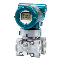
Digital Remote Sensor
Brand:
YOKOGAWA
| Category:
Transmitter
| Size: 10 MB
Table of Contents
Table of Contents
2
1 Introduction
7
Regarding this Manual
8
Trademarks
9
Safe Use of this Product
9
Warranty
10
2 Handling Cautions
11
Model and Specifications Check
11
Unpacking
11
Storage
12
Selecting the Installation Location
12
Pressure Connection
12
Waterproofing of Cable Conduit Connections and DRS Cable
13
Restrictions on Use of Radio Transceivers
13
Insulation Resistance and Dielectric Strength Test
13
Installation of an Explosion-Protected Instrument
14
FM Approval
14
ATEX Certification
19
Iecex Certification
22
Name Plate
25
3 Component Description
26
High Pressure Side Transmitter (Master)
26
Low Pressure Side Transmitter (Slave)
27
4 Installation
28
Precautions
28
Mounting
28
Connecting the DRS Cable
31
Mounting the C10FR Flushing Connection Ring
31
Mounting to Pressure Detector Section
31
Mounting to Process Flange
32
Affixing the Teflon Film
33
Tank Spud Mounting Method
33
Rotating Transmitter Section
35
Changing the Direction of Integral Indicator
35
5 Wiring
36
Wiring Precautions
36
Selecting the Wiring Materials
36
Connections of External Wiring to Terminal Box
36
Power Supply Wiring Connection
36
External Indicator Connection
36
Connecting The Hart Configuration Tool
37
Check Meter Connection
37
Wiring
37
Loop Configuration
37
Wiring Installation
37
DRS Cable Connection
38
Wiring through a Cable Gland
38
Wiring through a Wiring Metal Conduit
41
Removing DRS Cable with Cable Gland
41
Removing DRS Cable Running through a Wiring Metal Conduit
41
Fixing the DRS Cable
42
Grounding
42
Power Supply Voltage and Load Resistance
42
6 Operation
43
Preparation for Starting Operation
43
Zero Point Adjustment
44
Starting Operation
45
Shutting down Operation
45
Venting or Draining Transmitter Process-Detector Section
45
Draining Condensate from C10FR Flushing Connection Ring
46
Venting Gas from C10FR Flushing Connection Ring
46
Local Parameter Setting
47
Local Parameter Setting (LPS) Overview
47
Activating Local Parameter Setting
49
Parameter Setting Review
49
Tag Number Configuration
50
Differential Pressure Unit Configuration
50
Differential Pressure Lrv/Urv Configuration
50
Damping Time Constant Configuration
51
Output Mode Configuration
52
Display Out 1 Configuration
52
Re-Range By Applying Actual Pressure (Lrv/Urv)
52
Save or Cancel
52
Abort Configuration
53
Abort Configuration (Menu)
53
Abort Configuration (Parameter)
53
Local Parameter Setting Lock
53
Others
53
7 HART Communication
54
Connection
54
Integral Indicator Display at Power-On
54
Aligning Configuration Tool DD And Device Revision
55
Setting Parameters Using The Dtm
55
Connecting Dpharp And Configuration Tool
56
Setting Parameters
56
Menu Tree
56
DD and DTM Menu Tree
56
Basic Setup
57
Setting Process Variables
57
Tags and Device Information
57
Measuring Range
58
Unit
58
Differential Pressure Damping Time Constant
59
Output Mode
59
Output Signal Low Cut
60
Detail Setup
61
Pressure Damping Time Constant
61
Pressure Signal Setup
61
Bi-Directional Flow Measurement Setup
62
Impulse Line Connection Orientation Setup
62
Analog Signal Variable Range Setup
63
Integral Indicator Display Mode
63
Integral Indicator Setup
63
Display Temperature Unit Setup
65
Zero Point Adjustment and Span Adjustment
65
Analog Output Adjustment
68
CPU Error Burnout Switch and Hardware Write Protection
69
External Switch Mode
69
Software Write-Protect
69
Signal Characterizer Setup
70
Alarm Setup
71
Test Output, Simulation, and Squawk
72
Burst Mode
73
Multidrop Mode
79
Diagnostics
81
Self-Diagnostics
81
Checking Using the HART Configuration Tool
81
Checking with Integral Indicator
81
Status Information
81
NE107 Status Information
82
Advanced Diagnostics
83
What Is the Multi Sensing Process Monitoring Function
83
Impulse Line Blockage Detection
84
Blockage Determination
86
Combination of the Reference Value and Blockage Detection Result
87
Operation Parameters
89
Operating Procedure
91
Alert and Alarm Setup
92
Condition Confirmation
94
Checking the Blockage Detection Operating Capacity
95
Reference Value Acquisition
95
ILBD Execution
96
Tuning
96
ILBD Parameter List
98
Resetting the Reference Value
98
Heat Trace Monitoring
101
Alarm Generation
102
Flg Temp Coef Setting
102
Heat Trace Monitoring Parameter List
103
8 Maintenance
104
Overview
104
Calibration Instrument Selection
104
Calibration
106
Disassembly and Reassembly
107
Replacing the Integral Indicator
107
Replacing The Cpu Board Assembly
108
Cleaning and Replacing the Capsule Assembly
109
Troubleshooting
110
Basic Troubleshooting
110
Troubleshooting Flowcharts
110
Alarms and Countermeasures
112
9 Parameter Summary
128
10 General Specifications
141
Appendix 1. Safety Instrumented Systems Installation
142
A1.1 Scope and Purpose
142
A1.2 Using the Transmitter for an SIS Application
142
A1.2.1 Safety Accuracy
142
A1.2.2 Diagnostic Response Time
142
A1.2.3 Setup
142
A1.2.4 Required Parameter Settings
142
A1.2.5 Proof Testing
142
A1.2.6 Repair and Replacement
143
A1.2.7 Startup Time
143
A1.2.8 Firmware Update
143
A1.2.9 Reliability Data
143
A1.2.10 Lifetime Limits
144
A1.2.11 Environmental Limits
144
Application Limits
144
A1.3 Definitions and Abbreviations
144
A1.3.1 Definitions
144
A1.3.2
144
Abbreviations
144
Appendix 2. ILBD Check List
145
Revision Information
150
Advertisement
YOKOGAWA Dpharp EJX530A User Manual (49 pages)
Absolute Pressure and Gauge Pressure Transmitters
Brand:
YOKOGAWA
| Category:
Transmitter
| Size: 1 MB
Table of Contents
Table of Contents
2
1 Introduction
4
Regarding this Manual
4
Safe Use of this Product
5
Warranty
6
ATEX Documentation
7
2 Handling Cautions
8
Model and Specifications Check
8
Unpacking
8
Storage
8
Selecting the Installation Location
9
Pressure Connection
9
Waterproofing of Cable Conduit Connections
9
Restrictions on Use of Radio Transceivers
9
Insulation Resistance and Dielectric Strength Test
9
Installation of an Explosion-Protected Instrument
10
FM Approval
10
CSA Certification
12
CENELEC ATEX (KEMA) Certification
14
Iecex Certification
17
EMC Conformity Standards
18
Pressure Equipment Directive (PED)
18
Low Voltage Directive
19
3 Component Names
20
4 Installation
21
Precautions
21
Mounting
21
Rotating Transmitter Section
22
Changing the Direction of Integral Indicator
23
5 Installing Impulse Piping
24
Impulse Piping Installation Precautions
24
Connecting Impulse Piping to a Transmitter
24
Routing the Impulse Piping
24
Impulse Piping Connection Examples
25
6 Wiring
26
Wiring Precautions
26
Selecting the Wiring Materials
26
Connections of External Wiring to Terminal Box
26
Power Supply Wiring Connection
26
External Indicator Connection
26
Communicator Connection
26
Check Meter Connection
27
Status Output Connection
27
Wiring
27
Loop Configuration
27
General-Use Type and Flameproof Type
27
Intrinsically Safe Type
27
Wiring Installation
27
General-Use Type and Intrinsically Safe Type
27
Flameproof Type
28
Grounding
28
Power Supply Voltage and Load Resistance
28
7 Operation
29
Preparation for Starting Operation
29
Zero Point Adjustment
30
Starting Operation
31
Shutting down the Transmitter
31
Setting the Range Using the Range-Setting Switch
31
8 Maintenance
33
Overview
33
Calibration Instruments Selection
33
Calibration
33
Disassembly and Reassembly
35
Replacing the Integral Indicator
35
Replacing the CPU Board Assembly
36
Cleaning and Replacing the Capsule Assembly
36
Troubleshooting
38
Basic Troubleshooting
38
Troubleshooting Flowcharts
38
Alarms and Countermeasures
40
9 General Specifications
41
Standard Specifications
41
Model and Suffix Codes
44
Optional Specifications
44
Dimensions
47
YOKOGAWA Dpharp EJX530A Installation Manual (60 pages)
Differential Pressure and Pressure Transmitters
Brand:
YOKOGAWA
| Category:
Transmitter
| Size: 11 MB
Table of Contents
Table of Contents
1
1 Introduction
2
For Safe Use of Product
4
Warranty
6
2 Handling Cautions
7
3 Installation
35
Mounting
35
4 Installing Impulse Piping
40
5 Wiring
45
Wiring Precautions
45
Wiring
48
Grounding
52
6 Operation
53
Preparation for Starting Operation
53
7 Errors and Countermeasures
56
Advertisement
Advertisement
Related Products
YOKOGAWA Dpharp EJX510A
YOKOGAWA DP harp EJX510A
YOKOGAWA DP harp EJX530A
YOKOGAWA DpharpEJX vigilantplant EJX Series
YOKOGAWA DPharp EJX Series
YOKOGAWA Dpharp EJX310A
YOKOGAWA Dpharp EJX210A
YOKOGAWA DP harp EJX110A
YOKOGAWA DP harp EJX130A
YOKOGAWA DP harp EJX310A
YOKOGAWA Categories
Measuring Instruments
Test Equipment
Transmitter
Controller
Media Converter
More YOKOGAWA Manuals
Login
Sign In
OR
Sign in with Facebook
Sign in with Google
Upload manual
Upload from disk
Upload from URL