YOKOGAWA DPHARP EJA210E User Manual
Flange mounted differential pressure transmitters
Hide thumbs
Also See for DPHARP EJA210E:
- Installation manual (57 pages) ,
- Installation manual (60 pages) ,
- Installation manual (66 pages)

Subscribe to Our Youtube Channel
Related Manuals for YOKOGAWA DPHARP EJA210E


Summary of Contents for YOKOGAWA DPHARP EJA210E
- Page 1 User’s Manual Flange Mounted Differential Pressure Transmitters EJX210A and EJA210E IM 01C25C01-01E IM 01C25C01-01E 16th Edition...
-
Page 2: Table Of Contents
Mounting the Flushing Connection Ring ............4-3 4.5.1 Mounting to Pressure Detector Section ..........4-3 4.5.2 Mounting to Process Flange .............. 4-3 Affixing the Teflon Film ..................4-4 16th Edition: July 2021 (YK) IM 01C25C01-01E All Rights Reserved, Copyright © 2004, Yokogawa Electric Corporation... - Page 3 Toc-2 Installing Impulse Piping ................. 5-1 Impulse Piping Installation Precautions ............5-1 5.1.1 Connecting Impulse Piping to the Transmitter ........5-1 5.1.2 Routing the Impulse Piping ..............5-1 Impulse Piping Connection Examples ............5-2 Wiring ......................6-1 Wiring Precautions ................... 6-1 Selecting the Wiring Materials .................
- Page 4 Functional Safety Manual (Document No.: TI 01C25A05-01EN or TI 01C25A05-21EN for option code SLT) and follow the instructions and procedures described there.The document can be downloaded from the website of Yokogawa. (Website address: https://www.yokogawa.com/solutions/products-platforms/field-instruments/) In order to satisfy the requirement of Safety Instrumented System, executing parameters setting is required.
-
Page 5: Introduction
TI 01C25A05-01EN or TI 01C25A05-21EN for option code SLT) and follow the instructions and NOTE procedures described there.The document can be downloaded from the website of Yokogawa. This manual describes the hardware (Website address: configurations of the transmitters listed in below. https://www.yokogawa.com/solutions/products-... -
Page 6: Regarding This Manual
Yokogawa’s injury. It may also be used to alert against unsafe written permission. practices. • Yokogawa makes no warranty of any kind with regard to this manual, including, but not limited IMPORTANT to, implied warranty of merchantability and fitness for a particular purpose. -
Page 7: Safe Use Of This Product
WARNING WARNING • The instrument must be installed by an engineer or technician who has an expert • Yokogawa will not be liable for malfunctions knowledge of this instrument. Operators are or damage resulting from any modification not permitted to carry out wiring unless they made to this instrument by the customer. - Page 8 (h) Authorized Representative in EEA • In relation to the CE Marking, The authorised representative for this product in the EEA (European Economic Area) is: Yokogawa Europe B.V. Euroweg 2, 3825 HD Amersfoort,The Netherlands Control of Pollution Caused by the Product This is an explanation for the product based on “Control of Pollution caused by Electronic Information...
-
Page 9: Warranty
- Use of the product in question in a location not conforming to the standards specified by Yokogawa, or due to improper maintenance of the installation location. - Failure or damage due to modification or repair by any party except Yokogawa or an approved representative of Yokogawa. - Malfunction or damage from improper relocation of the product in question after delivery. -
Page 10: Handling Cautions
<2. Handling Cautions> Handling Cautions Unpacking This chapter provides important information on how to handle the transmitter. Read this carefully before Keep the transmitter in its original packaging to using the transmitter. prevent it from being damaged during shipment. The transmitters are thoroughly tested at the Do not unpack the transmitter until it reaches the factory before shipment. -
Page 11: Selecting The Installation Location
<2. Handling Cautions> Selecting the Installation Pressure Connection Location WARNING The transmitter is designed to withstand severe environmental conditions. However, to ensure • Never loosen the process connector and that it will provide years of stable and accurate flange bolts when an instrument is installed performance, take the following precautions when in a process. -
Page 12: Restrictions On Use Of Radio Transceivers
<2. Handling Cautions> Restrictions on Use of Radio • Insulation Resistance Test Transceivers 1) Short-circuit the + and – SUPPLY terminals in the terminal box. In case of 1 to 5 V output, IMPORTANT short-circuit the SUPPLY+, SUPPLY – and A (VOUT +) terminals. -
Page 13: Installation Of An Explosion-Protected Instrument
EJA-E transmitters upon shipment from the construction may be compromised and the factory are certified by the applicable agency in instrument may be hazardous to operate. Please combination with those transmitters. The plugs contact Yokogawa before making any repair or which are marked with the symbols “◊ Ex” on modification to an instrument. their surfaces are certified only in combination with the EJX/EJA-E series transmitters. - Page 14 In case Nonincendive Field Wiring Concept is used for the interconnection, FM-approved Associated Nonincendive Field Wiring Apparatus, which meets the Only personnel authorized by Yokogawa above conditions, must be used as the General Purpose Equipment. The General Purpose Equipment connected to the Associated Apparatus must not Electric Corporation can repair the equipment.
-
Page 15: Csa Certification
CAN/CSA-E60079-11:02 location. CAN/CSA-E60079-15:02 Note 4. Maintenance and Repair CAN/CSA-C22.2 No.60529 • The instrument modification or parts ANSI/ISA-12.27.01 replacement by other than authorized representative of Yokogawa Electric Corporation is prohibited and will void Factory Mutual Explosionproof Approval. IM 01C25C01-01E... - Page 16 • Intrinsically Safe for Class I, Division 1, replacement by other than authorized Groups A, B, C & D, Class II, Division 1, representative of Yokogawa Electric Groups E, F & G, Class III, Division 1 Corporation and Yokogawa Corporation •...
- Page 17 <2. Handling Cautions> • Enclosure: Type 4X • All wiring shall comply with local installation • Temperature Code: T6...T4 requirements and local electrical code. • Ex d IIC T6...T4 • In hazardous locations, the cable entry • Enclosure: IP66/IP67 devices shall be of a certified flameproof •...
-
Page 18: Atex Certification
EPL Ga –50°C ≤ Tp ≤ +120°C replacement by other than authorized EPL Db T120°C –30°C ≤ Tp ≤ +120°C representative of Yokogawa Electric T100°C –30°C ≤ Tp ≤ +100°C Corporation and Yokogawa Corporation of T85°C –30°C ≤ Tp ≤ +80°C America is prohibited and will void Canadian EPL Db * T120°C –15°C ≤ Tp ≤ +120°C Standards Explosionproof Certification. T100°C –15°C ≤ Tp ≤ +100°C T85°C... - Page 19 II 2 D Ex comply with the construction described in the certificate documentation. • Enclosure: IP66 / IP67 Only personnel authorized by Yokogawa Electric • Temperature Class for gas-poof: Corporation can repair the equipment. T6, T5, and T4 • Ambient Temperature for gas-proof: –50 to 75°C (T6), –50 to 80°C (T5), and...
- Page 20 Care must be taken supplied. not to twist the conductor. • Only personnel authorized by Yokogawa • Cable glands, adapters and/or blanking Electric Corporation can repair the elements with a suitable IP rating shall...
- Page 21 A modification of the equipment would no longer • Specific Ex Marking: comply with the construction described in the II 3 G Ex ic IIC T4 Gc certificate documentation. • Ambient temperature: Only personnel authorized by Yokogawa Electric –30°C ≤ Ta ≤ +60°C Corporation can repair the equipment. –15°C ≤ Ta ≤ +60°C * • Process temperature: –30°C ≤ Tp ≤ +120°C...
-
Page 22: Iecex Certification
2-13 <2. Handling Cautions> (2) Electrical Connection NO.: Serial number and year of production* TOKYO 180-8750 JAPAN: A mark indicating the electrical connection type The manufacturer name and the address* is stamped near the electrical connection port. *1: The first digit in the three numbers next to the nine letters of the serial number appearing after “NO.” on the nameplate indicates the year of production. - Page 23 Note 2. Electrical Data A modification of the equipment would no longer Maximum Input Voltage (Ui) = 30 V comply with the construction described in the Maximum Internal Capacitance (Ci) = 27.6 nF certificate documentation. Maximum Internal Inductance (Li) = 0 μH Only personnel authorized by Yokogawa Electric Corporation can repair the equipment. IM 01C25C01-01E...
- Page 24 • The instrument modification or parts –50 to 80°C (T5), –50 to 75°C (T6) replacement by other than authorized • Supply Voltage: 42 V dc max. representative of Yokogawa Electric 32 V dc max. (F Fieldbus and Corporation is prohibited and will void IECEx...
-
Page 25: Emc Conformity Standards
CAUTION Note 4. Maintenance and Repair To meet EMC regulations, Yokogawa • The instrument modification or parts recommends that customers run signal wiring replacement by other than authorized through metal conduits or use shielded twisted-... -
Page 26: Pressure Equipment Directive (Ped)
2-17 <2. Handling Cautions> 2.11 Pressure Equipment 2.12 EU RoHS Directive Directive (PED) Applicable standard: EN IEC 63000 Applicable production sites are shown below. (1) General The condition of the RoHS compliant production sites are as follows: • EJX/EJA-E Series pressure transmitters are Japan, Germany, Saudi Arabia, India categorized as piping under the pressure accessories section of directive 2014/68/EU,... -
Page 27: Component Names
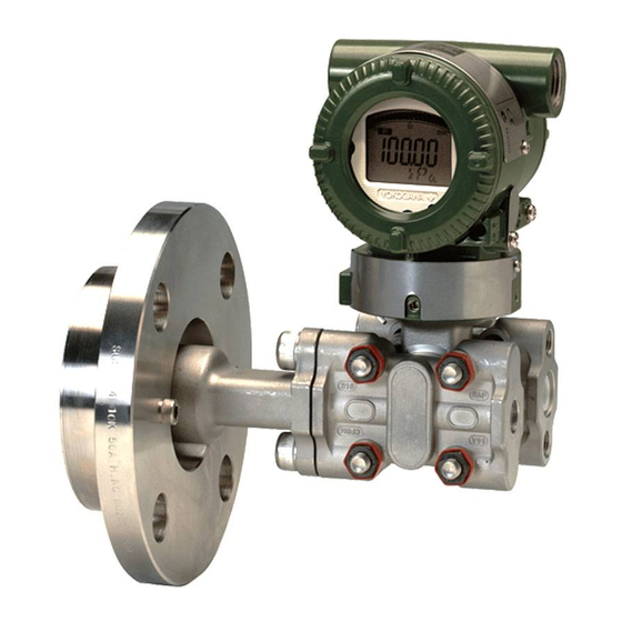
<3. Component Names> Component Names External indicator conduit connection (Note 1) Conduit connection Zero-adjustment screw Push button (Note 1) (See Subsection 7.6) Slide switch (Note 2) Process connection (low pressure side) Cover flange Process connector Bolt CPU assembly (Note 1) Integral indicator (Note 1) -
Page 28: Installation
<4. Installation> Installation Precautions Mounting Before installing the transmitter, read the cautionary The transmitter is mounted on a process using its notes in Section 2.4, “Selecting the Installation high-pressure side flange as shown in Figure 4.1. Location.” For additional informations and The mating flange, gasket, stud bolts and nuts are limitations according to the selected model, suffix to be procured by the customer. and option codes, please find information in each General Specifications sheet. -
Page 29: Rotating Transmitter Section
<4. Installation> Rotating Transmitter Section Changing Integral Indicator Direction The transmitter section can be rotated approximately 360° and can be fixed at any angle IMPORTANT within the above range. (The direction of the rotation is depending on the configuration of the • Always turn OFF power and shut off and instrument.) Note that there is a stopper which release pressures before disassembly. prevents the transmitter section from being rotated •... -
Page 30: Mounting The Flushing Connection Ring
<4. Installation> Mounting the Flushing 4.5.2 Mounting to Process Flange Connection Ring Tighten the bolts to completely close the gap between the ring and the pressure detector section. 4.5.1 Mounting to Pressure Detector The mating flange, gasket, stud bolts and nuts are Section to be procured by the customer. The flushing connection ring is mounted to high pressure side pressure detector section as shown in Figure 4.4. -
Page 31: Affixing The Teflon Film
<4. Installation> Affixing the Teflon Film The FEP Teflon option includes a teflon film and fluorinated oil. Before mounting the transmitter to the process flange, affix the teflon film as follows: IMPORTANT 1) Position the diaphragm so that the diaphragm is in a upward position. 2) Pour the fluorinated oil on the diaphragm and gasket area covering it completely and evenly. Be careful not to scratch the diaphragm or change the its shape. 3) Affix the teflon film over the diaphragm and gasket area. -
Page 32: Installing Impulse Piping
<5. Installing Impulse Piping> Installing Impulse Piping Impulse Piping Installation (2) Tightening the Process Connector Mounting Bolts Precautions After connecting the impulse line, tighten the The impulse piping that connects the process process connector mounting bolts uniformly. outputs to the transmitter must convey the process pressure accurately. -
Page 33: Impulse Piping Connection Examples
<5. Installing Impulse Piping> Impulse Piping Connection Examples Figure 5.2 shows examples of typical impulse piping connections. Before connecting the transmitter to the process, study the transmitter installation location, the process piping layout, and the characteristics of the process fluid (corrosiveness, toxicity, flammability, etc.), etc. and make appropriate changes and additions to the connection configurations. -
Page 34: Wiring
<6. Wiring> Wiring Wiring Precautions Connections of External Wiring to Terminal Box IMPORTANT ● Terminal Configuration • Lay wiring as far as possible from electrical noise sources such as large capacity transformers, motors, and power supplies. • Remove the electrical connection dust cap before wiring. -
Page 35: Power Supply Wiring Connection
<6. Wiring> 6.3.1 Power Supply Wiring Connection 6.3.3 Communicator Connection ■ 4 to 20 mA output, BRAIN / HART IMPORTANT IMPORTANT Connecting with the commercial AC power supply will damage the device. Be sure to use Analog output may change temporally in the DC power supply in the predetermined connecting with BRAIN terminal due to an initial range. -
Page 36: Check Meter Connection
<6. Wiring> Wiring 6.3.4 Check Meter Connection Available only for 4 to 20mA output type and when 6.4.1 Loop Configuration /AL is not specified. Since the DPharp uses a two-wire transmission Connect the check meter to the CHECK A (+) and system for 4 to 20 mA output, signal wiring is also SUPPLY –... -
Page 37: Wiring Installation
<6. Wiring> (3) 1 to 5 V output ■ Four wire connection Fasten the negative side wiring of both power Either three or four wire system is used. supply and signal line to the SUPPLY - terminal. Power supply line and 1 to 5 V signal line commonly Hazardous Location Nonhazardous Location use the SUPPLY - terminal. -
Page 38: Grounding
<6. Wiring> Grounding (2) Flameproof Type Wire cables through a flameproof packing adapter, Grounding is always required for the proper or use a flameproof metal conduit. operation of transmitters. Follow the domestic electrical requirements as regulated in each ■ Wiring cable through flameproof packing country. For a transmitter with a built-in lightning adapter. protector, grounding should satisfy ground resistance of 10Ω or less. -
Page 39: Operation
<7. Operation> Operation Preparation for Starting Operation Open Tank The EJ210 flange mounted differential pressure transmitter measures the levels or densities of liquids. This section describes the operation procedure for the EJ210 as shown in Figure 7.1 when measuring a liquid level in an open tank. (a) Confirm that there is no leak in the connecting part of the transmitter mounting flange. - Page 40 <7. Operation> ■ Confirming that Transmitter is Operating Using the integral indicator Properly • If the wiring system is faulty, the display stays blank. Using the BT200 • If the transmitter is faulty, an error code is displayed. IMPORTANT • Analog output may change temporally in connecting with BRAIN terminal due to an initial current flowed to it. To prevent communication signal affecting the upper...
-
Page 41: Zero Point Adjustment
<7. Operation> Zero Point Adjustment (1) When you can obtain Low Range Value from actual measured value of 0% (0 kPa, After completing preparations for operating the atmospheric pressure); transmitter, adjust the zero point. Zero point adjustment can be done by turning the transmitter’s zero-adjustment screw or by using the communicator. -
Page 42: Starting Operation
<7. Operation> Starting Operation Shutting Down Operation After completing the zero point adjustment, follow Turn off the power. the procedure below to start operation. NOTE 1) Confirm the operating status. If the output signal exhibits wide fluctuations (hunting) due to Whenever shutting down the transmitter for a periodic variation in the process pressure, use long period, detach the transmitter from the tank. the communicator to dampen the transmitter output signal. Confirm the hunting using a receiving instrument or the integral indicator,... -
Page 43: Draining Condensate
<7. Operation> 7.5.1 Draining Condensate 7.5.4 Venting Gas for Flushing Connection Ring 1) Gradually open the drain plug and drain the transmitter pressure-detector section. 1) Gradually open the vent screw to vent gas from (See Figure 7.2) the flushing connection ring. 2) When all accumulated liquid is completely 2) When the flushing connection ring is completely removed, close the drain plug. -
Page 44: Local Parameter Setting
<7. Operation> Local Parameter Setting 7.6.1 Local Parameter Setting (LPS) Overview WARNING Parameter configuration by the zero-adjustment screw and push button (integral indicator code E) offers easy and quick setup for parameters The local push button on the integral indicator of Loop test, Tag number, Unit, LRV, URV, must not be used in a hazardous area. When Damping,Output mode (linear/square root), Display it is necessary to use the push button, operate out 1, and Re-range by applying actual pressure... - Page 45 <7. Operation> screw Process Zero adjustment Measurement Display push Activate LPS mode push 1. Loop Test Select Output current Run/Cancel 2. Tag Number Edit Tag number Save/Cancel the value push 3. Press Unit Select Press unit Save/Cancel the value 4. Press LRV Edit Press LRV Save/Cancel the value push...
-
Page 46: Activating Local Parameter Setting
<7. Operation> 7.6.2 Activating Local Parameter Setting Press the push button on the integral indicator to activate the Local Parameter Setting mode. The transmitter will exit automatically from the Local Parameter Setting mode if no operation is carried out for 10 minutes. 7.6.3 Parameter Setting Review Current setting value for the below parameters are shown sequentially by each press of the push button. -
Page 47: Loop Test Configuration
<7. Operation> 7.6.4 Loop Test Configuration Loop test configuration can be changed as below. Output current value (4 mA, 12 mA or 20 mA) for Loop test can be selected by turning the zero-adjustment screw. Run ?/ Cancel ? Blinking Blinking [Available loop test] Select by the push button 4mA: 0% output 12mA: 50% output 20mA: 100% output screw Select by the push button or turning the push extemal adjustment... -
Page 48: Pressure Lrv/Urv Configuration
7-10 <7. Operation> 7.6.7 Pressure LRV/URV Configuration Pressure LRV and URV can be set. The number for each digit is changed by turning the zero-adjustment screw and set by pressing the push button. Please refer to 7.6.8 Damping Time Constant Configuration for how to change the numerical value. When the setting is out of the limit, an alarm will be generated. 7.6.8 Damping Time Constant Configuration The damping time constant for the amplifier assembly can be set. Quick Response Parameter is automatically set to ON when the damping time constant is set to less than 0.5 seconds. -
Page 49: Re-Range By Applying Actual Pressure (Lrv/Urv)
7-11 <7. Operation> 7.6.11 Re-range by applying actual Note 1: Wait until the pressure inside the pressure-detector section has stabilized before proceeding to the next pressure (LRV/URV). step. Note 2: If the pressure applied to the transmitter exceeds the This feature allows the lower and upper range previous LRV (or URV), the integral indicator may values to be setup with the actual input applied. -
Page 50: Abort Configuration
7-12 <7. Operation> 7.6.14 Abort Configuration 7.6.15 Local Parameter Setting Lock To disable parameter changes by the Local 7.6.14.1 Abort Configuration (Menu) Parameter Setting there are three different ways. Hold down the push button for over 2 seconds to Locked features exit the Local Parameter Setting mode. Communication Parameter •... -
Page 51: Maintenance
<8. Maintenance> Maintenance Overview Calibration Use the procedure below to check instrument WARNING operation and accuracy during periodic maintenance or troubleshooting. Since the accumulated process fluid may be 1) Connect the instruments as shown in figure 8.1 toxic or otherwise harmful, take appropriate care and warm up the instruments for at least five to avoid contact with the body or inhalation of minutes. - Page 52 <8. Maintenance> Table 8.1 Instruments Required for Calibration Name Yokogawa-recommended Instrument Remarks Power supply Model SDBT or SDBS distributor 4 to 20 mA DC signal Load resistor Model 2792 standard resistor [250 Ω ±0.005%, 3 W] Load adjustment resistor [100 Ω ±1%, 1 W] Voltmeter Model 2501 A digital multimeter Accuracy (10V DC range): ±(0.002% of rdg + 1 dgt) Digital Model MT220 precision digital manometer...
-
Page 53: Disassembly And Reassembly
Slotted adding an integral indicator to a transmitter. If screwdriver such modification is absolutely required, contact Allen wrenches JIS B4648 Yokogawa. One each, nominal 3, 4 and 2.5 mm Allen wrenches Wrench Width across flats, 17 mm This subsection describes the procedure for Torque wrench replacing an integral indicator. (See figure 8.3) -
Page 54: Replacing The Cpu Board Assembly
<8. Maintenance> ■ Mounting the CPU Assembly Output terminal cable 1) Connect the flat cable (with white connector) between the CPU assembly and the capsule. 2) Connect the output terminal cable (with brown Press connector). forward NOTE Slide switch Integral Make certain that the cables are free of pinching Zero- Boss indicator... -
Page 55: Replacing The Process Connector Gasket
If any abnormality appears in the measured values, receiving instrument? use the troubleshooting flow chart below to isolate and remedy the problem. Since some problems Inspect receiver. have complex causes, these flow charts may not identify all. If you have difficulty isolating or correcting a problem, contact Yokogawa service Environmental conditions Transmitter itself personnel. Check/correct Check transmitter. environmental conditions. Operating conditions Check/correct operating conditions. -
Page 56: Troubleshooting Flowcharts
Fully close equalizing valve, and fully open high pressure and low pressure valves. Adjust the zero point. Contact Yokogawa service personnel. Is there any pressure leak? F0807.ai Fix pressure leaks, paying particular attention to connections for impulse piping,pressure-detector section, etc. - Page 57 Provide lagging and/or cooling, or allow adequate ventilation. Were appropriate instruments used for calibration? Refer to Section 8.2 when selecting instruments for calibration. Is output adjusted correctly? Adjust the output. Contact Yokogawa service personnel. F0808.ai IM 01C25C01-01E...
-
Page 58: Alarms And Countermeasures
<8. Maintenance> 8.5.3 Alarms and Countermeasures Table 8.3 Alarm Message Summary Output Operation Indicator Cause Countermeasure during Error None AL. 01 Sensor problem. Outputs the signal (Hold, High, or Replace capsule when error CAP. ERR Low) set with parameter. keeps appearing even after Capsule temperature sensor restart. -
Page 59: General Specifications
<9. General Specifications> General Specifications Please refer to the following General Specifications list for the specifications, model, suffix and option codes, and external dimensions of each product. The General Specifications can be downloaded from the website of Yokogawa. Website address: https://www.yokogawa.com/solutions/products-platforms/field-instruments/ ■ General Specifications List Model Document Title Document No. EJX110A Differential Pressure Transmitter GS 01C25B01-01EN EJX120A Differential Pressure Transmitter GS 01C25B03-01EN EJX130A Differential Pressure Transmiter GS 01C25B04-01EN EJX210A Flange Mounted Differential Pressure Transmitter GS 01C25C01-01EN EJX310A... - Page 60 Rev-1 Revision Information Title : Flange Mounted Differential Pressure Transmitters EJX210A and EJA210E Manual No. : IM 01C25C01-01E Edition Date Page Revised Item Oct. 2004 — New publication 11th June 2014 • Add note for symbols. 2.9.2 • Revise category for CSA Nonincendive. 2-13 2.12 •...
- Page 61 Rev-2 Edition Date Page Revised Item 13th July 2015 2-15 2.10 • Change the note for EN 61326-2-5. 2-16 2.12 • Add C22.2 standards. 7.6.1 • Delete note for -Q in Figure 7.7. 7.6.3 • Change note in the figure. • Revise descriptions for EMC conformity standards. 9-6 to 9-11 •...
Need help?
Do you have a question about the DPHARP EJA210E and is the answer not in the manual?
Questions and answers