
Subscribe to Our Youtube Channel
Related Manuals for ACO FAM-P


Summary of Contents for ACO FAM-P
- Page 1 DOOR ENTRY SYSTEMS EXTENDED USER INSTRUCTION OF FAM-P AND FAM-PV DOOR ENTRY SYSTEMS 62-002 Suchy Las, ul. Diamentowa 7, tel./ fax 61 843 93 71 www.aco.com.pl...
-
Page 2: Table Of Contents
TABLE OF CONTENTS I. GENERAL INFORMATION ............................4 II. TECHNICAL PARAMETERS ............................5 III. USING THE PANEL ..............................6 IV. ADDITIONAL MODULES ............................10 V. MOUNTING AND CONNECTING THE PANEL ....................... 11 1- ASSEMBLY ........................................11 2 - CONNECTING THE PANEL ..................................12 3- WIRING DIAGRAMS FOR SINGLE PANEL INSTALLATION ....................... - Page 3 Hint: Brief description of programs in the service menu (installer mode), which is available in models with a numeric keypad: Programme No. Function Service door opening Change the opening code (resident, administrator) Setting E-lock reset time Setting the number of ringtones, permission to call apartment Turning the door opening signal off - on Setting one of four ringtones Test activation of the E-lock and uniphone call from apartment...
-
Page 4: General Information
ACC_v3 software (PC/Windows). In order to connect the panel to a PC, a special CDN-USB cable should be purchased separately (cable suitable for all ACO products). The software mentioned is available for free and can be downloaded from www.support.aco.com.pl... -
Page 5: Technical Parameters
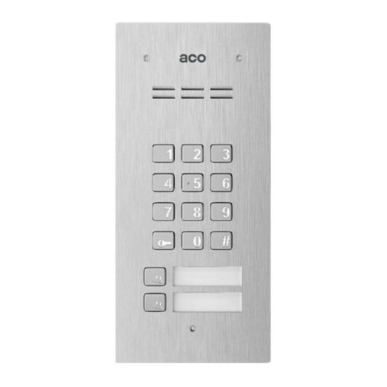
Support for proximity key fobs (version with built-in ACC): up to 192 key fobs FAM-P (audio) series includes versions of panels that are both surface mounted (NT) and flush mounted (PT), with code lock (ZS), with direct dial buttons (xNP, where x means the number of buttons) and with proximity key fob reader (ACC). -
Page 6: Using The Panel
CDNP panels or INSPIRO panels (FAM-P/PV-ZS panels with code lock only, without direct call buttons have this option set by default). In this case, the receiver in the apartment will start ringing after approx. - Page 7 Alternatively, the CDN-I/O module with dual relay outputs can be used. All FAM-P and FAM-PV panels feature an output for direct connection of an E-lock, also reversible E-lock. In order to connect a device other than an electric door strike, a relay needs to be connected in its place as per the diagram on page 15 or the CDN-PK relay module needs to be used.
- Page 8 #9. By default, the code table is only added to panels FAM-P-ZS and FAM-PV-ZS. For other versions of the panel, use the code table that is used in the panel/master panel or generate it using the "ACO Code Generator"...
- Page 9 Opening with additional push button The panel features an additional INPUT, which is configured by default as additional opening - when shorted to ground it activates door opening. Such opening while the call is pending completes the procedure of calling the apartment. This input can be connected to any NO button such as INS-OB, code lock, card access reader, motion detector etc.
-
Page 10: Additional Modules
The module parameters are set via the PC program for changing Familio panel settings (FAM_P). More information at www.aco.com.pl Description of module configuration - chapter XI. CDN-U signalling module with opening function... -
Page 11: Mounting And Connecting The Panel
V. MOUNTING AND CONNECTING THE PANEL ASSEMBLY Allen key 3 Allen key 3 Allen key 3 The panel should be assembled so as to minimise the impact of adverse weather conditions, in particular water. -11-... -
Page 12: Connecting The Panel
Install the flush-mounted back box (or flush-mounted adapted) in the appropriate wall opening, using holes 5 and rawlplugs (or screws) as well as gypsum; make sure that the back side of the box flange A is flush with the mounting surface. When mounting on a steel pole (similar structure with a maximum wall thickness of 32 mm), use an additional set of gaskets and screws 3 - available as an option. - Page 13 If the power supply has no PE connector, the MOD-PE-GND module can be used, available from Aco, to connect the PE conductor to the intercom system. Maximum lengths of signal cables (of the line or bus). The cross section (resistance) of the bus for digital transmission and audio track (LINE terminals) has a significant impact on the maximum bus length for both Audio and Video systems.
- Page 14 1. FAM-P panels only: 11.5V AC supply voltage is connected to the POWER (AC/AC) terminals, while if 15V DC power supply is used, the supply voltage is connected to the +DC (+ELOCK) and -DC (GND) terminals. 2. FAM-PV panels only: use only DC supply voltage of 15V DC and connect it to the +DC (+ELOCK) and -DC (GND) terminals of the panel.
- Page 15 "ELOCK" terminals with an additional 100 - 470µF electrolytic capacitor (depending on relay type), as per the diagram: ACO offers off-the-shelf CDN-PK modules, which can also be used. The panel may also work with reversible E-lock (closed after applying voltage). The same wiring diagram applies and the activation of this option is done via the PC program and the Z1 jumper must be installed in the panel (available under the panel terminals).
-
Page 16: 3- Wiring Diagrams For Single Panel Installation
3- WIRING DIAGRAMS FOR SINGLE PANEL INSTALLATION Audio panel installation with passive receivers should be connected as per the diagram below: -16-... - Page 17 The installation of audio panels with active receivers should be connected as per the diagram below: -17-...
- Page 18 The installations of audio panel with additional external camera and monitors should be connected as per the diagram below: To monitor or splitter -18-...
- Page 19 Video panel installation with one monitor should be connected as per the diagram below: NOTE! If the system features only one monitor, no video splitter is necessary and the monitor is connected at the end of the UTP bus leaving the panel. It is then absolutely necessary to connect the monitor power supply by connecting the bus cable: orange and brown together to "+DC"...
- Page 20 Video Panel with several monitors should be connected as per the diagram below: Rozdzielacz / Splitter Rozdzielacz / Splitter -20-...
-
Page 21: Installation And Connection Of Receivers
Familio series panels are suitable for combining a number of panels in one door entry system. Connect the system as per the diagram. Familio panels (FAM-P and FAM-PV) are versatile and the same type of panel can be used as both master and slave panel. - Page 22 During a call or conversation, the image will automatically be shown only from this panel (the image cannot be switched). In standby mode (no call) only the master panel can be used to control door opening (default option) or a second gate/function F2 (after changing the panel settings). After switching on the preview in the receiver in standby mode (no call), the image will be displayed from the Master panel (default setting) or from the Slave panel (after changing the panel settings and depending on the installation layout).
-
Page 23: Installation Of The Slave Panel
A system in which multiple FAM-P and FAM-PV panels are installed will operate correctly only if the number of physical addresses in the system remains at 150 or below (from the pool of 255). If the number of apartments exceeds 150 or if their numbers repeat, use the Inspiro+ or CDNP series panels (which support 255 apartments). -
Page 24: Wiring Diagram Of Installation With Multiple Panels
Installer’s code door opening time, ringtone (to identify the panel from which the call originated) other settings At the same time, for easier operation by users, it is recommended to set the same door opening codes in all panels (or the same code tables - then the door opening codes will be the same for all apartments). - Page 25 Installation of multiple audio panels with active receivers should be connected as per the diagram below: -25-...
- Page 26 Installation of multiple audio panels with additional external camera and multiple monitors should be connected as per the diagram below: Kolejne piętra Next floors Rozdzielacz / Splitter Sumator bez kamery Intermediate combiner no camera -26-...
- Page 27 Installation with multiple video panels and monitors should be connected as per the diagram below: Rozdzielacz / Splitter Sumator pośredni do FAM-PV Intermediate combiner for FAM-PV -27-...
- Page 28 Installation with multiple video panels and INSPIRO/CDNP panel should be connected as per the diagram below: Klatka / budynek Y Staircase / building Y Kolejne pietra Next floors Klatka / budynek X Staircase / building X Rozdzielacz / Splitter Rozdzielacz / Splitter Sumator pośredni do FAM-PV Intermediate combiner for FAM-PV...
- Page 29 Installation with multiple video panels, distributed among buildings / staircases should be connected as per the diagram below: Klatka / budynek X Staircase / building X Kolejne pietra Next floors Klatka / budynek Y Staircase / building Y Kolejne pietra Rozdzielacz / Next floors Splitter...
- Page 30 Installation with two panels, the first of which is an Audio panel should be connected as per the diagram below (example 4): Kolejne pietra Next floors Rozdzielacz / Splitter...
-
Page 31: Doorman Function
All settings can be accessed and archived using a PC and the free "FAM_P” software (can be downloaded from www.support.aco.com.pl). An optional programming cable (CDN- USB) is required to connect the panel to a PC; the cable must be purchased separately. -
Page 32: Service Door Opening
All panel settings are stored in permanent memory and are not lost when the power is turned off. Panels without numeric keypad (code lock) can only be programmed via a PC. To enter service menu (panel settings programming mode) on panels with numeric keypad, press the "... -
Page 33: Modification Of Administrator's Initial Access Code
Note that when using the Code Table, (which can be generated from www.support.aco.com.pl which is supplied for versions with numeric keypad only), the access codes correspond to physical addresses set in the receiver, which is important when offsets are pre-set. When factory settings are restored, so are the codes, to the pre-set code table. -
Page 34: Setting One Of Four Ringtones
If restoring memory settings via a PC is also disabled, it will be impossible to unlock the panel. Then only the manufacturer may restore the default installer’s password after returning the device to Aco service (proof of purchase of the device or confirmation of the right to configure the device is required). -
Page 35: Setting The Direct Call Button Address
Any code table can be generated and name tag printed along with instruction for residents on www.support.aco.com.pl. XI. PANEL PROGRAMING VIA A PC The "FAM_P" software can be downloaded from www.support.aco.com.pl. It can be used to configure all options available in the panel. Parameter: Option... - Page 36 Parameters part 1 and 2: Option Functionality Additional INPUT Function activated by short-circuiting additional INPUT Time delay between INPUT contacts shorting and Opening (ELOCK Opening delay output activation). The function “Opening after delay" must also be INPUTa activated Automatic opening of the E-lock after the end of the countdown from the Opening after “Further door opening pulse"...
- Page 37 Description of Application Settings Remar operation example Activation of the OUTPUT Gate control with third IN=0 For P2 Port, the function for a pre-set time after wire from the receiver OUT=t (t: time from 1 to 255 works only during a call closing the INPUT (only INS- UP720M, INS- s) NrF=0...
- Page 38 Example settings: Settings Remar Opening the second gate Port P1: Port P2: Connect outputs of port P1 and P2 in using the code ("double IN=x (x: has no IN=x (x: has no parallel ("N" with "N", "NO" with "NO" ) key"), using the F2 button effect) effect)
-
Page 39: Installing The Button For Additional Input
The direct call buttons select physical addresses, respectively, from the bottom: between 1 and 6 Code table with the default or most recently entered number (only FAM-P-ZS and FAM-PV- Installer’s password "1507 0000" No administrator code 1 and 2 ... -
Page 40: Maintaining Cleanliness
Additional range set to from 1 to 255 Code opening without key (except FAM-P-ZS and FAM-PV-ZS) Code for the bottom button (apartment 1): 1111 (except FAM-P-ZS and FAM-PV-ZS) Code for the top button (apartment 2): 2222 (except FAM-P-ZS and FAM-PV-ZS) ... -
Page 41: Troubleshooting
XVIII. TROUBLESHOOTING Check power supply. Turn the power off for approx. 15s and turn it Keypad not working on again, if this doesn’t work - notify the maintenance staff. The probable cause is malfunctioning of one or more After dialling the uniphones.
Need help?
Do you have a question about the FAM-P and is the answer not in the manual?
Questions and answers