
Related Manuals for ACO CDNP6ACC


Summary of Contents for ACO CDNP6ACC
- Page 1 EXTENDED USER INSTRUCTION FOR THE CDNP5, CDNP6 (CDNP6ACC) DIGITAL DOOR ENTRY SYSTEM ACO Sp. z o.o. sp. komandytowa, 62-002 Suchy Las, ul. Diamentowa 7, phone/fax +48 790 709 062 www.aco.com.pl...
-
Page 2: Table Of Contents
Table of contents I. GENERAL INFORMATION ............................. 3 II. TECHNICAL PARAMETERS ..........................5 III. OPERATION ................................6 IV. DESCRIPTION OF ADDITIONAL AND SPECIAL MODULES ............... 10 V. OPERATION OF THE CDNP UNIT ........................15 VI. INSTALLATION OF THE UNIT .......................... 15 WIRING DIAGRAM - INSTALLATION WITH ONE UNIT .................. -
Page 3: General Information
P23 PROGRAMMING THE ACTIVATION OF THE “WEZWIJ SERWIS” [call service] MESSAGE DISPLAY . 60 P24 PROGRAMMING ADDITIONAL “OD-DO” [from-to] RANGE ............... 61 P25 LINE TEST - TESTING UNIPHONES IN THE INSTALLATION ..............61 XIII. CHANGING THE UNIT LANGUAGE ......................62 XIV. - Page 4 CDN-I/O input/output module). With CDN-USB cable and corresponding "CDNP" or "ACC" software (for key fob management by CDNP6ACC) downloaded free of charge from www.aco.com.pl, it is possible to program settings, create backups and transfer settings to other units. For detailed information on the operation and capabilities of CDNP units refer to this manual.
-
Page 5: Technical Parameters
Use the optional CDN-USB cable and the computer software that can be downloaded free of charge from www.aco.com.pl to program settings, create backups and transfer settings to other units. Unit settings can be managed using the "CDNP"... -
Page 6: Operation
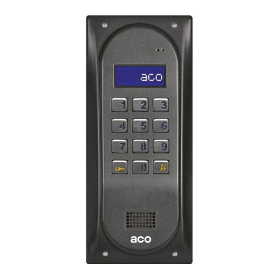
III. OPERATION In standby (factory settings) the unit display shows "aco". Using the P22 software, this can be changed to any other 6-character inscription or to 6 different screens (6 characters each) can be entered using a PC, displayed in cycles with a fixed interval. - Page 7 Additional numbers can assigned to the same uniphone so that it can be called using three different numbers (for instance two additional numbers and one primary number). Each such additional number may be configured with different ringing parameters (ring tone, volume, number of signals). If the primary numbers and additional numbers overlap, the latter have priority and calling in these cases is always made according to their settings.
- Page 8 Full table with residents’ codes or residents’ name tags together with use instruction can be printed using the "ACO Code Generator" available at www.aco.com.pl - user zone (“download"). A name tag may include a logo and one line of text for company name and phone number etc..
- Page 9 For this unit door opening is also possible via an additional module such as: CDN I-O, CDN ACC proximity card and key fob reader, or internal proximity key reader (CDNP6ACC) built into the unit. 9. Automatic opening when calling Automatic door opening after the first ringing tone. When the handset is not hung up and this function is enabled, the door will open automatically after the first ringing tone.
-
Page 10: Description Of Additional And Special Modules
Control of the built-in second relay OUTPUT: The OUTPUT exit (CDNP6 Master units only) can be activated upon pressing the F2 button in the receiver or entering the user code - in which case the "key" button must be pressed twice before entering the code, which is the same as the basic access code. - Page 11 "EXTMOD2" input of the unit and programmed directly from the keypad (P19 program) or via the special CDN-USB cable and using the appropriate software ("230E") which can be downloaded free of charge from www.aco.com.pl (Note: for modules version 7.00 and above, programming is possible via a PC only). 4 different start screens can be uploaded using this software (2 x 16 characters);...
- Page 12 "M-xNP" (P21) program, or via a computer, via the special CDN-USB cable and using the appropriate software ("FAM_P" from v1.3) downloaded free of charge from www.aco.com.pl. The frames are screwed with screws using a 3mm allen key. 6N module...
- Page 13 "M-xNP" (P21) program, or via a computer, via the special CDN-USB cable and using the appropriate software ("FAM_P" from v1.3) downloaded free of charge from www.aco.com.pl. 5N module - The illuminated window, 68mm wide, 40mm high,...
- Page 14 PAL signal into a differential signal transmitted in ACO video door entry system bus, based on UTP (min. cat 5e). This type of bus is used for all video inside units.
-
Page 15: Operation Of The Cdnp Unit
CDN-I/O Input-Output Module This module features two programmable ports: P1 and P2. Each of these ports has an INPUT and a relay OUTPUT. Inputs can be used for calling or opening and outputs can be used as control of opening an additional entrance gate, switching on the staircase lighting, etc. - Page 16 Avoid locations where the camera lens may be exposed to direct, perpendicular, light (from the sun, street lamps, etc.). The base plate for surface mounting of the unit is installed to the floor with rawlplugs or appropriate screws. Install the flush-mounting frame of the unit in the appropriate wall opening using rawlplugs and gypsum (wait for the gypsum to dry before screwing the outside unit to the mounting frame).
- Page 17 In case of passive audio receivers (2-wire receivers) the door entry unit is supplied from a mains transformer, the supply voltage is 11.5VAC, connection to AC/AC terminals (12V~). Recommended mains transformer is TR 11.5V 1.2A or TR DIN 11.5V 1.2A, available from ACO.
- Page 18 For VIDEO systems, 15VDC supply voltage is connected to combiner module terminals: +15V and GND. In both cases the recommended power supplies are available from ACO. It is possible to connect a buffer power supply to the same terminals (buffer power supply must ensure 15V, alternatively use an off-the-shelf inverter that supplies 15V from 12V to 15V input voltage).
- Page 19 ACO offers off-the-shelf CDN-PK modules. Relay contacts can be used as needed - it is recommended to power the unit connected to relay contacts from a separate power supply. Do not connect other inductive loads (such as an E-lock) via a relay from the same transformer that powers the door entry unit.
- Page 20 With additional wires (refer to the beginning of the chapter for information) and with CDNVRau-DIN active splitters (offered by ACO) to amplify the video signal, video installations may have up to 1000 m.
-
Page 21: Wiring Diagram - Installation With One Unit
WIRING DIAGRAM - INSTALLATION WITH ONE UNIT Installation with one unit is wired as shown below: * CDNP6 only All connections in the installation must be soldered! - Page 22 Video installation with one door entry unit is wired as shown below: Line No. Line No. Remove jumper at the floor Aux. power Out 2 Out 4 supply Aux. power supply ON ON ON ON ON ON ON ON ON ON ON ON 1 - white/amber 2 - amber...
-
Page 23: Installation And Connection Of Uniphones
The unit will start counting down approx. 30s, displaying it (this time is needed for the uniphones to establish the work conditions), then the software version number and "ACO" intro will be displayed. Note! During the final start-up of the unit, the countdown (30s)must not be interrupted as this time is needed to charge uniphones - otherwise the control panel may malfunction (it may stop ringing, break connection, etc). -
Page 24: Volume Level Adjustment
VIII. VOLUME LEVEL ADJUSTMENT The volume level of the unit is pre-set, but it can be changed to suit individual conditions and needs. The volume level settings can be accessed, when connected to the uniphone, as follows: - adjust the sensitivity of the unit microphone using the "MIC" potentiometer - adjust the unit speaker volume level using the "SPK"... - Page 25 The slave unit support further door opening function. Upon opening the door is opened from the unit (during the conversation, using the access code or card/key fob), waiting for door opening will be automatically activated in other units, but only in those which support the uniphone from which the conversation was carried out or to which the access code or card is assigned.
-
Page 26: Slave Unit Installation
The rest of the installation requires no modifications (no additional cable to the master unit - two existing uniphone line wires are enough). It is very convenient when installing additional units, for example on building upper floor. 1.- SLAVE UNIT INSTALLATION Separate line to which all uniphones (or video display units) to be supported by a slave unit will be connected. -
Page 27: Wiring Diagrams For Installations With Multiple Units
2.- WIRING DIAGRAMS FOR INSTALLATIONS WITH MULTIPLE UNITS Building / staircase X Building / staircase Y further uniphones further uniphones Optional additional slave units Optional additional slave units connected the same way as the first connected the same way as the first two, e.g. - Page 28 Diagrams No. 1 - Video system: Line No. Line No. Remove jumper at Out 2 Out 4 the floor Aux. power supply Aux. power supply 1 - white/amber 2 - amber 3 - white/green 4 - blue 5 - white/blue 6 - green 7 - white/brown Act.
-
Page 29: Programming The Slave Unit
If a camera is not required for the slave unit, the "Intermediate combiner without camera" (CDNVSpbk) must be used If a camera is not required on the Master unit, connect it as a classic Audio system. In this case use the combiner module (not the Intermediate combiner module) for the first Slave unit and connect the Master line to the ML terminals the conventional way. -
Page 30: Numbering In The Hotel System
NUMBERING IN THE HOTEL SYSTEM The function of dialling in a hotel system is activated in order to enable calling from one unit to multiple zones (staircases, buildings, etc.), in which the numbering repeats. This situation is common for instance for a master unit at the entrance to a housing estate with many buildings or staircases. -
Page 31: Unit Programming
It is possible to read all settings of the unit, modify them and archive them using a PC (via the CDN-USB cable) and free CDNP software (www.aco.com.pl). In order to enter the installation programs, press the "key" button and enter the eight-digit password (1507xxxx) - this operation is confirmed by a modulated “up”... -
Page 32: P0 Service Activation Of E-Lock
The installer’s password in units is set to "0000" and must be changed after installation! (program P7). EXAMPLE: To enter the unit programming function with 2222 installer’s code, press the "key" followed by 1507 (fixed digits) and 2222. 1 5 0 7 2 2 2 2 Upon entering the installer programming, the display will briefly show "PROGR"... -
Page 33: P1 Modification Of User's Access Code (Resident's Or Administrator's Code)
P1 MODIFICATION OF USER’S ACCESS CODE (RESIDENT’S OR ADMINISTRATOR’S CODE) The code can be used to activate E-lock (for instance to open the front door) or to activate another device connected to the ELOCK output (for instance via the CDN-PK relay module); it can also be used, upon pressing the “key” button twice, to activate the relay output of the CDN-I/O module (for instance to open gate 2) - P18 program. -
Page 34: P2 Setting Silent Or Loud Ringing
P2 SETTING SILENT OR LOUD RINGING Hi-Lo This program is used for changing the ringing volume (1 or 2) in selected apartment. Enter the program, wait for "Nbr ?” to be displayed, then enter the number of the apartment for which the ringing volume is to be changed (or enter "0"... -
Page 35: P4 Turning The Door Opening Signal On - Off In The Apartment
In a multi-panel system, the ringtone disabling works only on the panel on which ringtones were set. The receiver in a disconnected apartment will still emit the door opening signal when opening using the access code (use P4 menu to disable it). Now the value “Nbr ?”... -
Page 36: P5 Service Uniphone Call From Apartment
P5 SERVICE UNIPHONE CALL FROM APARTMENT SfCal The option of service uniphone call from apartment is activated during the system installation. With this option the installer can self-check if the uniphone works OK (ringing, broadcast channel and opening) directly from the apartment. The procedure is as follows: after pressing the uniphone opening button three times, with the handset lifted, the unit starts searching for the uniphone with lifted handset, selecting numbers in sequence (within the “From"... - Page 37 Now, each time the "key" button is pressed, the E-lock is released for the pre-set time. Use the "#" button to turn the function off. Upon entering the program, the current value of the E-lock set time and delay is displayed (default setting is "04"...
-
Page 38: P7 Changing The Installer's Password
Delay of E-lock activation after closing the terminals of additional input is also available in slave units - program P12. P7 CHANGING THE INSTALLER’S PASSWORD IPass This program is used to set a new 4-digit installer’s password (installer programming access password). The default password is "0000”. This is how to set a new installer’s password to 5482. - Page 39 - “ ” last supported call number (by default "255"). The block diagram for programming parameters is shown in the figure below: After entering the program, the display shows " " and the current value of the pre-set offset is displayed. At this point, a new offset value can be entered (0 to 998) or the "key"...
- Page 40 Example with subtracting (difference between the number selected on keypad and the offset value). When the number of apartment 1 starts with 301, the physical address "1" is set in the receiver of that apartment, the physical address "2" is set in the receiver of apartment 302, and so on.
-
Page 41: P10 Hotel System Dialling Settings
Then apartments with number above this number cannot be opened with an access code and "Error!" will appear on the display. When the call number offset is pre-set, the “From" and “To" parameters are entered as actual call numbers (dialled from keypad), rather than the number physically set on the uniphone board. - Page 42 *for CDNP5 bit2 = 1 in P16 Any number of slave units working in the Hotel mode and in zones. The number of zones in the system can be set from 1 to 10. Their settings can be programmed directly from the unit or using a PC. Dialling method: - Dialling the number requires entering the zone number (from 1 to 9, or 0 for zone 10) and then apartment number (1 - 99).
- Page 43 - “Adr”: physical address for additional numbers. Two additional call numbers can be entered for each for which physical addresses set in uniphones can be defined. The block diagram for programming parameters is shown in the figure below: Before each parameter is specified, its currently set value is displayed. Confirm this value with the "key"...
-
Page 44: P11 Entering New Access Code Table
When the parameters have been saved correctly, "Ready" will appear on the display. By default, all values are set to zero, meaning all zones and additional numbers are inactive. P11 ENTERING NEW ACCESS CODE TABLE Tabel This program is used to enter the four-digit number of the code table, used by the unit to generate 255 individual access codes for residents. -
Page 45: P13 Setting One Of Four Ringtones
After entering the program, the unit display shows " Adr" and the currently set value. Enter a value from the range 0 to 255 and confirm with the key button. Depending on the value entered, the panel will perform the appropriate function. Pressing the "#"... -
Page 46: P14 Searching Misplaced Or Defective Uniphones
The search can be terminated at any time by pressing the "#" button. When using non-ACO uniphones this function may not work properly. An additional test is the line test - the P25 program... - Page 47 If this function is activated and the handset is not hung up, the E-lock will be activated automatically after the first ringing signal. If the handset was hung up during the first ringing tone, the unit works normally - the handset can be picked up and communication is possible.
-
Page 48: P16 Bity-1 Unit Parameter Settings
If a three-digit value is entered for "Num" and "Adr" parameters, or a one-digit value for the remaining parameters, the unit will save it automatically, without confirmation, and move on to programming the next parameter. One and two- digit values for the "Num" and "Adr" parameter must be confirmed with the "key”... -
Page 49: Bit1.- Enable Further Door Opening After Further Door Opening After Time [1Tw]
Bit1.- Enable further door opening after further door opening after time [1opn.] When enabled, this bit causes automatic activation of the E-lock (auto-open) after the delay time pre-set in P6 when using further door opening or closing the INPUT on the master unit. Bit2.- for CDNP5: Enable and disable operation as master unit [2Nad]. -
Page 50: Bit7.- Enabling Access Code Change By The User [7Zmko]
(clearing the unit memory settings). When the bit is enabled ("1"), upon turning on the unit and when the countdown is completed (when the unit displays "ACO” briefly), pressing "2,5,8" at the same time will initiate the factory settings restore procedure. -
Page 51: Bit1.- Selecting The Image Preview Camera In Standby [1Vids]
The bit enables unit interface with Multimaster module. The module is used to connect up to 5 master units (for instance on main entrances) in a single point (star connection) in order to shorten the installation length. Refer to at www.aco.com.pl. for detailed information. By default, all bits are disabled. -
Page 52: P18 Parameters Of "Cdn-I/O" Additional Input-Output Module
P18 PARAMETERS OF "CDN-I/O” ADDITIONAL INPUT-OUTPUT MODULE InOut This program is used to set the parameters for the CDN I/O module (module extending inputs and outputs of the unit). The I/O module features two ports, P1 and P2. Each port has one input (shorted to ground for setup) and relay output (NO and NC contacts with maximum load 2A for 30VDC or 1A for 125VAC). - Page 53 Set the following parameters in the program: - “IN”: enter value 0 to 255 for input of the first or second port (“IN1” or “IN2”) - “OU”: enter output activity time in seconds from 0 do 255 of the first or second port (“OU1”...
- Page 54 ACC reader. This function can be used to open the entrance gate (no additional wires are required for the installation and the installation works only with ACO uniphones). Function No. 3: Activation of the output for a pre-set time after pressing any keypad button, additional module button or for CDNP6 (P1 port only) after pressing the uniphone opening button three times with the handset lifted.
- Page 55 The block diagram for programming parameters is shown in the figure below: function value time (seconds) - function No. value time (seconds) Before each parameter is specified, its currently set value is displayed. Confirm this value with the "key" button to automatically proceed to programming the next parameter (without changing it).
- Page 56 Activation of the Gate control using standard IN=x (x: has no Control from two wires from the camera uniphone works only OUTPUT for a pre-set effect) and code from the keypad during a call time after pressing the OUT=t (t: time from F2 key on the uniphone 1 to 255 s) NrF=2 or after selecting the...
-
Page 57: P19 Programming The 230E Electronic Module
The CDN-230E module needs to be connected to a PC using special CDN-USB cable and the software can be downloaded free of charge from www.aco.com.pl. When the "Adres?" value is entered, "H-H" will appear on the panel screen, and the data assigned to that address will appear on the module screen. -
Page 58: P20 Programming The Acc Opening Module
Approve the entered text with the "key" button. The changes are stored in memory. The module display shows “saving data, please wait”. Sorting by alphabet is only possible with a PC program. If alphabetical sorting is enabled, it is not possible to add or edit individual names on the unit. Pressing the "#" key at any time (except when saving the data) exits the program without saving the changes. -
Page 59: P21 Programming The Name Module Using 2,6,10Np Buttons
“ACC” PC program for the CDN - ACC module. Connect the CDN - ACC module to a PC using the special CDN-USB cable and download the software free of charge from www.aco.com.pl. Time of card entering is limited to about 10s. -
Page 60: P22 Programming The Intro Text On The Display
INTRO This program is used to change the Intro text, which is displayed on the unit screen in standby. Bu default the text reads "aco". After entering the program, the display shows the current Intro text. Text is entered using the following panel keypad digits:... -
Page 61: P24 Programming Additional "Od-Do" [From-To] Range
Any higher value will disable this function. "0” will cause immediate display of the message. The time entered should be considered as a guide - after a year the difference may be even a few days. Any power failure periods are excluded from the time countdown. -
Page 62: Changing The Unit Language
To do so, switch off the unit power supply, wait approx. 10s and switch it on again. After the countdown, while the unit briefly displays "ACO", press 2,5,8 at the same time. If the factory settings restore is enabled (bit8=1 in P16) the unit will display "Reset!"... -
Page 63: Factory Settings
If the factory settings restore is disabled (bit8=0 in P16) the unit will display "Error! The factory reset procedure will not modify the code table number (entered in the P11 program), and all access codes are restored according to this code table number. -
Page 64: Maintaining Cleanliness
Ringtone for all apartments - No. 3, The number of ringing signals for all apartments - 2, E-lock release time - 4s, Reversible E-lock disabled, Further door opening function in slave units disabled, Additional input - value "0" (open). ... -
Page 65: Troubleshooting
TROUBLESHOOTING Check if 12V~ power supply is available. Disconnect the unit power Display and keypad supply for approx. 15s, if after reconnection it still does not work - won’t work notify the service. The probable cause is malfunctioning of one or more After dialling the uniphones. - Page 66 - Version 6.10 K-07: Minor bug fixes and modifications to the door opening signal. After switching off the door opening signal and entering the address with a code/card, no short ringing is heard in the handset. - Version 6.17 K-01: Version on CDNP 7.0 board. The unit displays "Zwar.L"...
- Page 67 Notes …………………………………………………………………………………………… …………………………………………………………………………………………… …………………………………………………………………………………………… …………………………………………………………………………………………… …………………………………………………………………………………………… …………………………………………………………………………………………… …………………………………………………………………………………………… …………………………………………………………………………………………… …………………………………………………………………………………………… …………………………………………………………………………………………… …………………………………………………………………………………………… …………………………………………………………………………………………… …………………………………………………………………………………………… …………………………………………………………………………………………… …………………………………………………………………………………………… …………………………………………………………………………………………… …………………………………………………………………………………………… …………………………………………………………………………………………… …………………………………………………………………………………………… …………………………………………………………………………………………… …………………………………………………………………………………………… …………………………………………………………………………………………… …………………………………………………………………………………………… …………………………………………………………………………………………… …………………………………………………………………………………………… …………………………………………………………………………………………… …………………………………………………………………………………………… …………………………………………………………………………………………… …………………………………………………………………………………………… …………………………………………………………………………………………… …………………………………………………………………………………………… …………………………………………………………………………………………… …………………………………………………………………………………………… …………………………………………………………………………………………… …………………………………………………………………………………………… …………………………………………………………………………………………… …………………………………………………………………………………………… …………………………………………………………………………………………… …………………………………………………………………………………………… ……………………………………………………………………………………………...
- Page 68 …………………………………………………………………………………………… …………………………………………………………………………………………… …………………………………………………………………………………………… …………………………………………………………………………………………… …………………………………………………………………………………………… …………………………………………………………………………………………… …………………………………………………………………………………………… …………………………………………………………………………………………… …………………………………………………………………………………………… …………………………………………………………………………………………… …………………………………………………………………………………………… …………………………………………………………………………………………… …………………………………………………………………………………………… …………………………………………………………………………………………… …………………………………………………………………………………………… …………………………………………………………………………………………… …………………………………………………………………………………………… …………………………………………………………………………………………… …………………………………………………………………………………………… …………………………………………………………………………………………… …………………………………………………………………………………………… …………………………………………………………………………………………… …………………………………………………………………………………………… …………………………………………………………………………………………… …………………………………………………………………………………………… …………………………………………………………………………………………… …………………………………………………………………………………………… IU0401envJ.2247 62-002 Suchy Las, ul. Diamentowa 7, tel./fax 61 843 93 72 www.aco.com.pl...
Need help?
Do you have a question about the CDNP6ACC and is the answer not in the manual?
Questions and answers