Table of Contents
Advertisement
Available languages
Available languages
Quick Links
EN
- Installation, operation and maintenance manual
IT
- Manuale di installazione, uso e manutenzione
PL
– Instrukcja instalacji, obsługi i konserwacji
Drawings of optional accessories
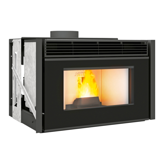
Jøtul PC 900
EN - Before use, read the general instructions of installation, use and maintenance carefully
IT - Prima dell'uso, leggere attentamente le istruzioni generali di installazione, uso e manutenzione
PL - Przed użyciem należy dokładnie zapoznać się z ogólną instrukcją instalacji, użytkowania i konserwacji
The instruction manual provided with the product must be kept throughout the entire period of the products use. Le
istruzioni fornite devono essere conservate per tutta la vita del prodotto. Instrukcje dostarczone z produktem muszą być
przechowywane przez cały okres użytkowania produktu.
Jøtul PC 900 / Jøtul PI 900
Jøtul PC 900
2
34
66
98
Advertisement
Chapters
Table of Contents

Related Manuals for Jøtul PC 900


Summary of Contents for Jøtul PC 900
- Page 1 Jøtul PC 900 / Jøtul PI 900 - Installation, operation and maintenance manual - Manuale di installazione, uso e manutenzione – Instrukcja instalacji, obsługi i konserwacji Drawings of optional accessories Jøtul PC 900 Jøtul PC 900 EN - Before use, read the general instructions of installation, use and maintenance carefully IT - Prima dell’uso, leggere attentamente le istruzioni generali di installazione, uso e manutenzione...
-
Page 2: Table Of Contents
ENGLISH TABLE OF CONTENTS INTRODUCTION ����������������������������������������������������������������� 3 8 DISPOSAL, RECYCLING AND SCRAPPING �������������20 1.1 Symbols ....................3 1.2 Use......................3 9 INITIAL CONFIGURATION ���������������������������������������������21 1.3 Purpose and content of the instruction manual .........3 9.1 Connection to an external chronothermostat ........21 1.4 Storage of the instruction manual ............3 1.5 Update of instruction manual ...............3 1.6 General information ................3 10 DESCRIPTION OF STOVE �����������������������������������������������21... -
Page 3: Introduction
ENGLISH 1 INTRODUCTION 1�5 UPDATE OF INSTRUCTION MANUAL This instruction manual is consistent with the technical Jøtul heating equipment (hereinafter referred to as pellet knowledge available at the time of introduction of the stoves) are designed and installed in accordance with stove for marketing. -
Page 4: Statutory Guarantee
ENGLISH 1�13 RATING PLATE - EN 61000-3-3:2014 /EC:2016 - EN 55014-2:2015 The rating plate is situated on the rear of the stove and EMF: contains all product data, including the manufacturer’s - EN 62233:2008 / EC:2008 reference number, registration number and markings LVD: 1�14 DELIVERY OF THE STOVE - EN 60335-1:2013 /EC:2014 /A11:2015 /A13:2017... -
Page 5: Warnings For Technical Maintenance Personnel
ENGLISH 2�2 WARNINGS FOR TECHNICAL Follow the routine and extraordinary maintenance schedule carefully. MAINTENANCE PERSONNEL Do not use the appliance without having first carried out Maintenance operations must be carried out only by daily cleaning. authorised and qualified personnel. Do not use the appliance if operation is abnormal, you Observe the prescriptions contained in this manual. -
Page 6: Fuel Properties
ENGLISH Do not sit/stand in front of the product in operation for This may lead to the introduction of sawdust into the long periods. stove’s container, which may cause jamming or blocking of the feed worm and damage to the worm’s drive motor. Incorrect use of the product or incorrect maintenance works may create a serious risk of explosion in the The properties of granulate must be compliant with the... -
Page 7: Location Of The Stove
ENGLISH Provide access to allow and cleaning of the appliance, the connection duct, and the smoke duct (or, if applicable, the coaxial smoke exhaust and air supply system). 5�2 LOCATION OF THE STOVE Attached are the minimum distances in centimetres (fig. ... -
Page 8: Smoke Evacuation
ENGLISH combustion air using a coaxial connection (exhaust pipe for smoke expulsion and another for aspiration air), so there is no need to have a classic air intake in the room. Decree No. 2008-1231 article R131-2 dispenses with the direct outside air intake since the device has its own air supply for appliances waterproof. -
Page 9: Installation
ENGLISH 6 INSTALLATION The fitter must have the Jøtul certificate, authorising installation of appliances fired with solid fuel. The insert can be installed on the wall adjacent to the chimney, with distribution of hot air to the front or to the sides, with an optional frame or without a frame. - Page 10 ENGLISH 5) Unfasten the four screws fastening the rails on the bottom wall of the insert (fig. 6.1.5). 6) Lift the insert and remove it from the rails of the load-bearing structure (fig. 6.1.6); 7) Unfasten the pallet fastening screws from the base and remove the pallet (fig.
- Page 11 ENGLISH 10) Place the insert back on the rails (fig. 6.1.10) 11) Reinstall the fastening screws previously removed in step 6.1.5 (fig. 6.1.11) 12) Push the appliance in until the very end of the rails (fig. 6.1.12) 13) Open the door, insert Allen key (A) into the limiter’s socket;...
-
Page 12: Installation Diagram
ENGLISH 6�2 INSTALLATION DIAGRAM (fig. 6.2.1) A) To properly install the smoke pipe between the insert and smoke duct, it must be tight, and all joints must be sealed. B) Rear exterior air inlet, maintain a minimum distance of 5 cm between the fireplace’s housing and the pipe supplying combustion air. -
Page 13: Connection Of Hot Air Distribution
ENGLISH 6�2�1 Positioning the room temperature sensor The sensor should be installed near the side or front inlets for convection air at the base of the fireplace’s housing. Stick the sensor’s grip on the air inlets (fig. 6.2.2). 6�3 CONNECTION OF HOT AIR DISTRIBUTION Only for version with air distribution�... -
Page 14: Loading Pellet
ENGLISH 6�4 LOADING PELLET Pellet is loaded through a flap made in the housing and connected with the insert by means of special accessories (optional)� Installation is carried out according to the instructions on the packaging� Do not use the smoke exhaust system to fill the pellet container�... -
Page 15: Making Technical Holes In The Lining
ENGLISH 6�5 MAKING TECHNICAL HOLES IN THE LINING The fireplace housing should be made solely by qualified personnel. Make technical holes in the fireplace housing for: A) placement of the control keyboard; B) warm air outlets; C) decompression grate; D) ventilation of the housing at the base; E) pellet loading door;... -
Page 16: Maintenance
ENGLISH 7 MAINTENANCE 7�1 SAFETY MEASURES Before performing any maintenance work, the following activities must be performed: • Check whether all parts of the insert are cold. • Check whether ash is fully extinguished. • Wear personal protection equipment as per Directive 89/391/EEC. -
Page 17: Extraordinary Maintenance
ENGLISH 7�2�3 Cleaning the combustion chamber Remove the interior plates from the combustion chamber (fig. 7.5) : using a vacuum cleaner for ash, clean the flue duct, consisting of the two bottom spaces (fig. 7.6). Repeat the previous activities in reverse, and reinsert the interior plates into the combustion chamber, making sure to position them properly. - Page 18 ENGLISH 7�3�1�1 Cleaning the worm feeder In the case of clogging of the pellet feeder from the container to the combustion chamber, proceed as follows: A) remove the protective grate from inside the container by unfastening four cross-head screws using a screwdriver; B) remove the fastening of the inspection plate (fig. 7.10);...
- Page 19 ENGLISH 7�3�3 Insert maintenance Perform at least once a year or whenever the insert signals the need for maintenance. When performing maintenance activities, the technician should: A) Open the door (1), remove the top panel (2), unfasten and remove both stoppers (3) (fig. 7.14) B) Remove the interior plates from the combustion chamber and vacuum the remaining ash (fig.
-
Page 20: Disposal, Recycling And Scrapping
ENGLISH 8 DISPOSAL, RECYCLING AND SCRAPPING The user is solely responsible for disposal and scrapping of the insert, and they must act according to the safety and environmental protection regulations binding in their country. Disposal and scrapping of the insert can be entrusted to third parties, under the condition that they are entities authorised to collect and process such waste. -
Page 21: Initial Configuration
ENGLISH 9 INITIAL CONFIGURATION After installation of the chronothermostat, the first firing of the insert must be performed manually, when Depending on the type of installation, the stove must be the chronothermostat is in “call” mode� Proceed in the properly configured in order to optimise its operation. same manner after power failure as well as after manual shutdown of the insert�... -
Page 22: Using The Control Keyboard
ENGLISH 10�1�2 Menu description ICON FUNCTION DESCRIPTION VALUES Power Setting working power. 1–5 Ventilation: Setting of air fan power in room OFF*, 1–5; Auto; Hi. *(if provided) Displays the room temperature and allows for programming the desired Temperature from 6°C to 51°C temperature. -
Page 23: Operating Parameters
ENGLISH 11 PRELIMINARY ACTIVITIES 10�3 OPERATING PARAMETERS The stove’s operation depends on user-defined parameters 11�1 FILLING WITH PELLET of Power, Ventilation and Temperature. The first activity to be performed before firing up the 10�3�1 Power change stove is to fill the pellet container. Power corresponds to the amount of heat generated Pellet should be put in the container using a small shovel. -
Page 24: Using The Stove
ENGLISH 11�3�2 Setting screen brightness a) Using keys , select the Configuration menu Screen brightness can be adjusted when the screen is in press standby mode. b) Select the item using button and confirm by pressing ”7” button a) Using keys , select the Configuration menu press c) Using button... -
Page 25: Work With Ambient Temperature Sensor Installed On The Stove
ENGLISH 13�1�2 Assigning programs to days of the week The stove will also shut down if the temperature continues to rise despite modulation. In this case, the stove will only This function makes it possible to assign up to 3 different start when the difference between the selected and actual programs to a given day. -
Page 26: Reignition Delta" Function
ENGLISH 13�3 “REIGNITION DELTA” FUNCTION 13�7 “KEYBOARD LOCK” FUNCTION The reignition delta is the number of degrees below the This function makes it possible to lock the keyboard in extinguishing temperature, which, when exceeded, will order to prevent unintended changes. cause the stove to reignite automatically. -
Page 27: Alarm Management
ENGLISH 14 ALARM MANAGEMENT Failure is signalled by means of the following procedure: 1) sound warning (beep), 2) lighting up of one of the following icons: 3) in the case of an alarm, the stove will be extinguished, 4) holding the “cancel” button displays the code of the alarm: CODE OF... -
Page 28: Electrical Diagram
ENGLISH ELECTRICAL DIAGRAM Jøtul PC 900 / Jøtul PI 900 t° t° t° UI / +16V I03 GND CN12 CN11 CN10 FUSE L ~220÷240 N exaust Air L Air R NOTE: Phase protection, added by customer. Do not change polarity! ~220÷240 Vac... -
Page 29: Technical Data
ENGLISH TECHNICAL DATA Jøtul PC 900 / Jøtul PI 900 (according to standard EN 14785) *Total thermal power (efficiency) 2,9 kW 9 kW Efficiency 94,5 % 90,7 % Smoke temperature 64,9 °C 124,4 °C Smoke flowrate 4,13 g/s 8,8 g/s... -
Page 30: Dimensions
ENGLISH DIMENSIONS Jøtul PC 900 74,5 O 60 256,5... - Page 31 ENGLISH DIMENSIONS Jøtul PI 900 74,5 138,5 138,5 O 60 256,5...
-
Page 32: Ce Label
ENGLISH CE LABEL Jøtul PC 900 JØTUL FRANCE SAS - 3, Chemin du Jubin – F-69574 Dardilly Cedex EN 14785:2006 DOP Nr.004725114 – N. B. 2456 Type: JØTUL PC 900 Matr. Nº LT000000000000000012345 Fuel type Pellet Nominal heat input PImax... - Page 33 ENGLISH CE LABEL Jøtul PI 900 JØTUL FRANCE SAS - 3, Chemin du Jubin – F-69574 Dardilly Cedex EN 14785:2006 DOP Nr.004725114 – N. B. 2456 Type: JØTUL PI 900 Matr. Nº LT000000000000000012345 Fuel type Pellet Nominal heat input PImax Reduced heat input PImin Nominal heat output...
- Page 34 ITALIANO INDICE INTRODUZIONE ��������������������������������������������������������������� 35 8 SMALTIMENTO, RICICLO E ROTTAMAZIONE ��������� 52 1.1 Simboli ....................35 1.2 Utilizzo ....................35 9 CONFIGURAZIONE INIZIALE ��������������������������������������� 53 1.3 Obiettivi e contenuto delle istruzioni..........35 9.1 Collegamento a un cronotermostato esterno ........53 1.4 Conservazione delle istruzioni .............35 1.5 Aggiornamento delle istruzioni ............35 1.6 Informazioni generali ................35 10 DESCRIZIONE DELLA STUFA ���������������������������������������...
-
Page 35: Introduzione
ITALIANO 1 INTRODUZIONE 1�5 AGGIORNAMENTO DELLE ISTRUZIONI Queste istruzioni corrispondono alle conoscenze tecniche I dispositivi di riscaldamento Jøtul (di seguito denominati disponibili al momento dell'immissione sul mercato della "stufe a pellet") sono costruiti e installati in conformità stufa. con le norme di sicurezza specificate nelle pertinenti Le stufe vendute con tutta la documentazione tecnica direttive europee. -
Page 36: Garanzia Legale
ITALIANO EMF: i dati del prodotto, inclusi il numero di riferimento del produttore, il numero di registrazione e la marcatura - EN 62233:2008 / EC:2008 LVD: 1�14 CONSEGNA DELLA STUFA - EN 60335-1:2013 /EC:2014 /A11:2015 /A13:2017 La stufa viene consegnata imballata in una scatola di - EN 60335-2-102:2007 /A1:2011 cartone e posizionata su un pallet di legno che consente di CPR:... -
Page 37: Avvertenze Per Il Personale Tecnico Addetto Alla Manutenzione
ITALIANO dopo aver completato il suo assemblaggio. L’utente non specializzato deve essere tutelato dall’accesso a qualunque parte possa esporlo a pericoli. 2�2 AVVERTENZE PER IL PERSONALE Non deve perciò essere autorizzato ad intervenire su parti TECNICO ADDETTO ALLA interne a rischio (elettrico o meccanico), nemmeno se è MANUTENZIONE prescritto il distacco dell’alimentazione elettrica. -
Page 38: Caratteristiche Del Combustibile
ITALIANO L’accumulo di pellet incombusto nel braciere dopo si trova in alto. Il coperchio deve essere sempre aperto una mancata accensione deve essere rimosso prima di durante il caricamento del pellet. procedere con un nuovo tentativo di accensione. Per motivi di sicurezza e per garantire il controllo della Se il braciere non viene pulito e sottoposto a interventi temperatura, non utilizzare ciocchi di legno tradizionali�... -
Page 39: Preparazione Del Sito Di Installazione
ITALIANO 5 PREPARAZIONE DEL SITO DI INSTALLAZIONE 5�1 CONSIDERAZIONI GENERALI Esistono diversi fattori che rendono la combustione più efficiente in termini di prestazioni termiche e bassa distanze emissione di sostanze inquinanti (monossido di carbonio CO-). Alcuni fattori dipendono dall’apparecchio in cui avviene la combustione, mentre altri dipendono dalle caratteristiche ambientali, dall’installazione e dal grado di manutenzione effettuato sull’apparecchio. -
Page 40: Estrazione Dei Fumi
ITALIANO l’aria dall’esterno per non inquinare l’aria ambiente. Puoi anche prendere aria direttamente nello spazio di scansione se è ventilato. La sezione delle griglie dello spazio di scansione deve corrispondere a 5 volte l’area delle griglie in cm² dell’area in m² del piano terra (Esempio: il piano terra di 100 m²... -
Page 41: Installazione
ITALIANO 6 INSTALLAZIONE L’installatore deve possedere il certificato Jøtul che lo autorizza al montaggio di dispositivi a combustibile solido. L’inserto può essere installato sulla parete adiacente al camino con distribuzione di aria calda verso la parte anteriore o laterale, con un telaio opzionale o senza telaio. 6�1 INSTALLAZIONE DELL’INSERTO SULLA PARETE DEL CAMINO Per consentire l’installazione in un alloggiamento di... - Page 42 ITALIANO 5) Svitare le quattro viti che fissano le guide sulla parete inferiore dell’inserto (fig. 6.1.5). 6) Sollevare l’inserto e rimuoverlo dalle guide della struttura portante (fig. 6.1.6). 7) Rimuovere dalla base le viti che fissano il pallet e rimuoverlo (fig. 6.1.7). 8) Posizionare la struttura portante dell’inserto nella posizione di installazione designata (1), contrassegnare e praticare 4 fori da Ø...
- Page 43 ITALIANO 10) Riposizionare l’inserto sui binari (fig. 6.1.10) 11) Reinstallare i bulloni di fissaggio precedentemente rimossi al punto 6.1.5 (fig. 6.1.11) 12) Spingere l’apparecchio fino alla fine delle guide (fig.1.12). 13) Aprire lo sportello, inserire la chiave a brugola (A) nella sede del limitatore;...
-
Page 44: Schema Di Montaggio
ITALIANO 6�2 SCHEMA DI MONTAGGIO (fig. 6.2.1) A) Per installare correttamente la canna fumaria tra l’inserto e la canalina dei fumi, questa deve essere ermetica e tutti i giunti devono essere sigillati. B) Presa d’aria esterna posteriore, assicurare una distanza minima di 5 cm tra l’alloggiamento del camino e il tubo di alimentazione dell’aria di combustione. -
Page 45: Collegamento Della Distribuzione Aria Calda
ITALIANO 6�2�1 Posizionamento del sensore di temperatura ambientale Il sensore deve essere installato vicino alle prese d’aria a convezione laterale o frontale alla base del camino. Attaccare il supporto del sensore sulle prese d’aria (fig. 6.2.1). 6�3 COLLEGAMENTO DELLA DISTRIBUZIONE ARIA CALDA Solo per la versione con distribuzione dell’aria�... -
Page 46: Caricamento Del Pellet
ITALIANO 6�4 CARICAMENTO DEL PELLET I pellet vengono caricati attraverso una serranda ricavata nell’alloggiamento e collegata all’inserto con accessori speciali (opzionali)� Eseguire l’installazione secondo le istruzioni sulla confezione� Non utilizzare il sistema di estrazione del fumo per riempire il serbatoio del pellet� Si sconsiglia l’installazione di accessori non originali�... -
Page 47: Praticare Fori Tecnici Nel Rivestimento
ITALIANO 6�5 PRATICARE FORI TECNICI NEL RIVESTIMENTO L’alloggiamento del camino deve essere realizzato solo da personale qualificato. Praticare dei fori tecnici nell’alloggiamento del camino per: A) posizionamento del tastierino di comando; B) prese dell’aria calda; C) griglia di decompressione; D) ventilazione dell’alloggiamento alla basa; E) sportello di caricamento del pellet;... -
Page 48: Manutenzione
ITALIANO 7 MANUTENZIONE 7�1 MISURE DI SICUREZZA Prima di eseguire qualsiasi intervento di manutenzione, procedere come segue: • Verificare che tutte le parti dell’inserto siano fredde. • Verificare che le ceneri siano completamente spente. • Indossare i dispositivi di protezione individuale definiti nella Direttiva 89/391/CEE. -
Page 49: Manutenzione Straordinaria
ITALIANO 7�2�4 Pulizia della camera di combustione Rimuovere le piastre interne dalla camera di combustione (fig. 7.5): Utilizzare un aspirapolvere per pulire il condotto dei fumi costituito dai due spazi inferiori (fig. 7.6). Ripetere i passaggi precedenti nell’ordine inverso e reinserire le piastre interne nella camera di combustione, accertandosi che siano posizionate correttamente. - Page 50 ITALIANO 7�3�2 Pulizia della coclea Se il tubo di alimentazione del pellet dal serbatoio alla camera di combustione è bloccato, procedere come segue: A) rimuovere la griglia protettiva all’interno del serbatoio svitando le quattro viti a croce con un cacciavite; B) rimuovere il fissaggio della piastra di ispezione (fig. 7.10);...
- Page 51 ITALIANO 7�3�4 Manutenzione dell’inserto Da eseguire almeno una volta all’anno o ogni volta che l’inserto richiede manutenzione. Durante la manutenzione, il tecnico dovrebbe: A) aprire lo sportello (1), rimuovere il pannello superiore (2), svitare e rimuovere entrambi i tappi (3) (fig. 7.14) B) rimuovere le piastre interne dalla camera di combustione e aspirare la cenere rimanente (fig. 7.15) C) rimuovere i tappi superiori dell’inserto e aspirare i...
-
Page 52: Smaltimento, Riciclo E Rottamazione
ITALIANO 8 SMALTIMENTO, RICICLO E ROTTAMAZIONE L’utente è l’unico responsabile dello smaltimento e della rottamazione dell’inserto e dovrà agire in conformità con le norme di sicurezza e protezione ambientale in vigore nel proprio Paese. Lo smaltimento e la rottamazione dell’inserto possono essere affidati a terzi, a condizione che siano enti autorizzati a raccogliere e trattare tali rifiuti. -
Page 53: Configurazione Iniziale
ITALIANO 9 CONFIGURAZIONE INIZIALE Dopo aver installato il cronotermostato, la prima accensione dell’inserto deve essere eseguita manualmente A seconda del tipo di installazione, la stufa deve quando il cronotermostato è in modalità „chiamata”� essere correttamente configurata per ottimizzarne il Procedere allo stesso modo dopo un’interruzione di funzionamento. -
Page 54: Utilizzo Del Tastierino Di Comando
ITALIANO 10�1�2 Descrizione del menu ICONA FUNZIONE DESCRIZIONE PROPRIETÀ Potenza Impostazione della potenza di lavoro. Ventilazione: Impostazione della potenza del ventilatore nella stanza OFF*,1–5; Auto; Hi. * (se prevista) Indica la temperatura ambiente e consente di programmare la temperatura Temperatura da 6°C a 51°C desiderata. -
Page 55: Parametri Di Funzionamento
ITALIANO 11 OPERAZIONI PRELIMINARI 10�3 PARAMETRI DI FUNZIONAMENTO Il funzionamento della stufa dipende dai parametri di 11�1 RIEMPIMENTO DEL PELLET Potenza, Ventilazione e Temperatura impostati dall'utente. La prima cosa da fare prima di accendere la stufa è 10�3�1 Cambio di potenza riempire il serbatoio del pellet. -
Page 56: Utilizzo Della Stufa
ITALIANO 11�3�2 Impostazione della luminosità dello schermo a) Servirsi dei pulsanti selezionare il menu Configurazione La luminosità dello schermo può essere regolata quando e premere lo schermo è in modalità standby. b) Scegliere la voce usando il pulsante e confermare ”7”... -
Page 57: Funzionamento Con Il Sensore Di Temperatura Ambiente Installato Sulla Stufa
ITALIANO 13�1�1 Impostazione dei programmi Quando la stufa viene accesa per la prima volta o dopo che è stata spenta tramite il pannello di controllo (pulsante a) Servirsi dei pulsanti selezionare il menu Configurazione ) deve essere nuovamente accesa tramite il tastierino e premere di comando�... -
Page 58: Funzione Economica „Modalità Eco
ITALIANO 13�1�3 Attivazione/disattivazione del timer 13�5 FUNZIONE DI „BLOCCO TASTIERINO” Questa funzione consente di bloccare il tastierino al fine di evitare modifiche involontarie. a) Con i pulsanti a freccia scegliere il menu Timer Per attivare/disattivare questa funzione: b) Confermare con il pulsante c) Con i pulsanti di scorrimento e selezione: "ON"... -
Page 59: Gestione Degli Allarmi
ITALIANO 14 GESTIONE DEGLI ALLARMI L’errore viene segnalato mediante la seguente procedura: 1) segnale acustico (bip), 2) illuminazione di una delle seguenti icone: 3) in caso di allarme la stufa si spegnerà, 4) tenendo premuto il pulsante „Annulla” viene visualizzato il codice di allarme: Codice ALLARME / DESCRIZIONE... -
Page 60: Schema Di Collegamento Elettrico
ITALIANO SCHEMA DI COLLEGAMENTO ELETTRICO Jøtul PC 900 / Jøtul PI 900 t° t° t° UI / +16V I03 GND CN12 CN11 CN10 FUSE L ~220÷240 N Fumi Aria L Aria R ATTENZIONE : Protezione fase, aggiunta dal cliente. Non cambiare la polarizzazione! ~220÷240 Vac... -
Page 61: Dati Tecnici
ITALIANO DATI TECNICI Jøtul PC 900 / Jøtul PI 900 (in conformità con la norma EN 14785) *Potenza termica totale 2,9 kW 9 kW Efficienza 94,5 % 90,7 % Temperatura del fumo 64,9 °C 124,4 °C Portata di fumo 4,13 g/s... -
Page 62: Dimensioni
ITALIANO DIMENSIONI Jøtul PC 900 74,5 O 60 256,5... - Page 63 ITALIANO DIMENSIONI Jøtul PI 900 74,5 138,5 138,5 O 60 256,5...
-
Page 64: Etichetta Ce
ITALIANO ETICHETTA CE Jøtul PC 900 JØTUL FRANCE SAS - 3, Chemin du Jubin – F-69574 Dardilly Cedex EN 14785:2006 DOP Nr.004725114 – N. B. 2456 Type: JØTUL PC 900 Matr. Nº LT000000000000000012345 Fuel type Pellet Combustibile Nominal heat input... - Page 65 ITALIANO ETICHETTA CE Jøtul PI 900 JØTUL FRANCE SAS - 3, Chemin du Jubin – F-69574 Dardilly Cedex EN 14785:2006 DOP Nr.004725114 – N. B. 2456 Type: JØTUL PI 900 Matr. Nº LT000000000000000012345 Fuel type Pellet Combustibile Nominal heat input PImax Potenza Massima di ingresso Reduced heat input...
- Page 66 POLSKI SPIS TREŚCI WSTĘP ����������������������������������������������������������������������������������� 67 8 UTYLIZACJA, RECYKLING I ZŁOMOWANIE �������������84 1.1 Symbole ....................67 1.2 Użytkowanie ..................67 9 KONFIGURACJA POCZĄTKOWA ���������������������������������85 1.3 Cele i treść instrukcji ................67 9.1 Podłączenie do zewnętrznego chronotermostatu ......85 1.4 Przechowywanie instrukcji ..............67 1.5 Aktualizacja instrukcji ................67 1.6 Informacje ogólne ................67 10 OPIS PIECA �������������������������������������������������������������������������85 1.7 Gwarancja ustawowa ................
-
Page 67: Wstęp
POLSKI 1 WSTĘP 1�5 AKTUALIZACJA INSTRUKCJI Instrukcja ta jest zgodna z wiedzą techniczną dostępną Urządzenia grzewcze Jøtul (zwane dalej piecami w chwili wprowadzania pieca do obrotu. na pellet) są konstruowane i montowane zgodnie Piece sprzedawane wraz z całą niezbędną dokumentacją z przepisami bezpieczeństwa określonymi w odpowiednich techniczną... -
Page 68: Gwarancja Ustawowa
POLSKI Zastosowano następujące zharmonizowane normy i/lub Wymiana elementu przed jego całkowitym zużyciem przepisy: pomaga zapobiegać nagłym uszkodzeniom, które mogłyby spowodować szkody fizyczne i/lub materialne. EMCD: W regularnych odstępach czasu należy przeprowadzać - EN 55014-1:2017 kontrole konserwacyjne wymienione rozdziale - EN 61000-3-2:2015 „Konserwacja”. -
Page 69: Ostrzeżenia Dla Pracowników Obsługi Technicznej
POLSKI • musi używać narzędzi wyposażonych w izolacją Dzieci nie mogą bawić się urządzeniem. Czyszczenie, za elektryczną; które odpowiada użytkownik, nie może być wykonywane • musi zadbać, aby obszar wykorzystywany podczas przez dzieci pozostawione bez nadzoru. montażu/demontażu był wolny od przeszkód. Przed wykonaniem jakiejkolwiek operacji użytkownik lub •... -
Page 70: Właściwości Paliwa
POLSKI • rozmiar Ø 6 mm Zabrania się obsługi urządzenia przy otwartych drzwiczkach� • maks� długość 30 mm Zabrania się używania urządzenia, jeśli szyba w drzwiach lub uszczelki są uszkodzone. • maks� wilgotność: od 8% do 10% wilgotności� Wszelkiego rodzaju nieuprawniona obsługa Piec wyposażony jest w zbiornik na pellet o pojemności wymiany części zamiennych na nieoryginalne zagrażają... -
Page 71: Zdjęcie Pieca Z Palety Transportowej
POLSKI Za podnoszenie ciężarów odpowiada wyłącznie operator wózka widłowego. Dopilnować, aby dzieci nie bawiły się materiałami opakowaniowymi (np� folią plastikową i polistyrenem)� Ryzyko zadławienia! 4�1 ZDJĘCIE PIECA Z PALETY odległości TRANSPORTOWEJ Aby zdjąć piec z palety transportowej, postępować zgodnie ze wskazówkami zawartymi w niniejszej instrukcji (patrz punkt 6). -
Page 72: Powietrze Do Spalania
POLSKI (G oznacza, że połączenie jest odporne na pożar komina, a xx to minimalna bezpieczna odległość w milimetrach) 5�3 POWIETRZE DO SPALANIA Podczas pracy piec pobiera określoną ilość powietrza z pomieszczenia, w którym jest zainstalowany (z wyjątkiem niektórych produktów, które pobierają powietrze bezpośrednio z zewnątrz)�... -
Page 73: Instalacja
POLSKI 6 INSTALACJA Instalator musi posiadać certyfikat Jøtul uprawniający do montażu urządzeń na opał stały. Wkład można zainstalować na ścianie przylegającej do komina z rozprowadzeniem ciepłego powietrza do przodu lub na boki, z opcjonalną ramą lub bez ramy. 6�1 INSTALACJA WKŁADU NA ŚCIANIE KOMINOWEJ Aby umożliwić... - Page 74 POLSKI 5) Odkręcić cztery śruby mocujące szyny na ścianie dolnej wkładu (Rys. 6.1.5). 6) Podnieść wkład i zdjąć go z szyn konstrukcji nośnej (Rys. 6.1.6); 7) Wykręcić śruby mocujące paletę z podstawy i wyjąć paletę (Rys. 6.1.7). 8) Umieścić konstrukcję nośną wkładu w wyznaczonym miejscu montażu (1), zaznaczyć...
- Page 75 POLSKI 10) Umieścić ponownie wkład na szynach (Rys. 6.1.10) 11) Ponownie zamontować uprzednio usunięte śruby mocujące usunięte w punkcie 6.1.5 (Rys. 6.1.11) 12) Wepchnąć urządzenie aż do samego końca szyn. (Rys. 6.1.12) 13) Otworzyć drzwiczki, włożyć klucz imbusowy (A) do gniazda ogranicznika; przekręcić dźwignię zamykającą w prawo, do pozycji (B), aby zablokować...
-
Page 76: Schemat Montażu
POLSKI 6�2 SCHEMAT MONTAŻU (rys. 6.2.1) A) Aby prawidłowo zamontować rurę dymową pomiędzy wkładem i kanałem dymowym, musi ona być szczelna, a wszystkie złącza uszczelnione. B) Tylny zewnętrzny wlot powietrza, zapewnić minimalną odległość 5 cm między obudowa kominka, a rura doprowadzającą powietrze do spalania. C) Zaleca się... -
Page 77: Podłączenie Rozprowadzania Gorącego Powietrza
POLSKI 6�2�1 Umieszczenie czujnika temperatury otoczenia Czujnik powinien być zainstalowany w pobliżu bocznych lub przednich otworów wlotowych powietrza konwekcyjnego u podstawy obudowy kominka. Przykleić uchwyt czujnika na wlotach powietrza (rys. 6.2.2). 6�3 PODŁĄCZENIE ROZPROWADZANIA GORĄCEGO POWIETRZA Tylko dla wersji z rozprowadzaniem powietrza� Podłączenie rozprowadzenia dla ogrzewania pojedynczych pomieszczeń... -
Page 78: Ładowanie Pelletu
POLSKI 6�4 ŁADOWANIE PELLETU Pellet jest ładowany przez klapę wykonaną w obudowie i połączoną z wkładem za pomocą specjalnych akcesoriów (opcjonalnie)� Instalację przeprowadza się zgodnie z instrukcją podaną na opakowaniu� Nie używać systemu wyciągowego dymu do napełniania zbiornika na pellet� Nie zaleca się instalowania nieoryginalnych akcesoriów� Rozsypanie pelletu na zewnątrz zbiornika może spowodować... -
Page 79: Wykonywanie Otworów Technicznych W Obudowie
POLSKI 6�5 WYKONYWANIE OTWORÓW TECHNICZNYCH W OBUDOWIE Obudowa kominkowa powinna być wykonana wyłącznie przez wykwalifikowany personel. Wykonać otwory techniczne w obudowie kominkowej dla: A) umiejscowienia klawiatury sterującej; B) wylotów ciepłego powietrza; C) kratki dekompresyjnej; D) wentylacji obudowy u podstawy; E) drzwiczek załadunkowych pellet; Otwory muszą... -
Page 80: Konserwacja
POLSKI 7 KONSERWACJA 7�1 ŚRODKI BEZPIECZEŃSTWA Przed wykonaniem jakichkolwiek prac konserwacyjnych należy wykonać następujące czynności: • Sprawdzić, czy wszystkie części wkładu są zimne. • Sprawdzić, czy popioły są całkowicie wygaszone. • Nosić środki ochrony osobistej przewidziane w dyrektywie 89/391/EWG. • Sprawdzić, czy główny wyłącznik jest wyłączony. •... -
Page 81: Konserwacja Nadzwyczajna
POLSKI 7�2�4 Czyszczenie komory spalania Wyjąć płyty wewnętrzne z komory spalania (rys. 7.5) : za pomocą odkurzacza do popiołu oczyścić kanał spalinowy składający się z dwóch dolnych przestrzeni (rys. 7.6). Powtórzyć poprzednie czynności w odwrotnej kolejności i ponownie włożyć płyty wewnętrzne do komory spalania, zwracając uwagę... - Page 82 POLSKI Odkurzyć pozostałości znajdujące się wewnątrz trójnika (rys. 7.9) Wepchnąć urządzenie do samego końca. Włożyć klucz imbusowy (A) do gniazda zwalniającego ogranicznika; przekręcić dźwignię zamykającą w kierunku ruchu wskazówek zegara, do pozycji (B), aby zablokować szyny, zamknąć drzwiczki. 7�3�2 Czyszczenie podajnika ślimakowego W razie zatkania przewodu doprowadzającego pellet ze zbiornika do komory spalania, postępować...
- Page 83 POLSKI 7�3�3 Konserwacja wkładu Konserwację wkładu należy przeprowadzać przynajmniej raz w roku lub za każdym razem, gdy wkład sygnalizuje konieczność wykonania konserwacji. Podczas wykonywania czynności konserwacyjnych, technik powinien: A) otworzyć drzwiczki(1), zdjąć panel górny (2), odkręcić i zdjąć obie górne zaślepki (3) (rys. 7.14) B) wyjąć...
-
Page 84: Utylizacja, Recykling I Złomowanie
POLSKI 8 UTYLIZACJA, RECYKLING I ZŁOMOWANIE Za utylizację i złomowanie wkładu odpowiada wyłącznie użytkownik, który musi działać zgodnie z obowiązującymi w jego kraju przepisami w zakresie bezpieczeństwa i ochrony środowiska. Utylizację i złomowanie wkładu można powierzyć osobom trzecim, pod warunkiem że są one podmiotami upoważnionymi do zbierania i przetwarzania takich odpadów. -
Page 85: Konfiguracja Początkowa
POLSKI 9 KONFIGURACJA Po zainstalowaniu chronotermostatu pierwsze rozpalenie wkładu musi być wykonane ręcznie, gdy chronotermostat POCZĄTKOWA jest się w trybie „wywołanie”� Postępować w ten sam sposób po awarii zasilania, jak również po ręcznym W zależności od rodzaju instalacji piec musi być wyłączeniu wkładu�... -
Page 86: Użycie Klawiatury Sterującej
POLSKI 10�1�2 Opis menu IKONA FUNKCJA OPIS WARTOŚCI Ustawianie mocy roboczej. 1–5 Wentylacja: Ustawianie mocy wentylatora powietrza w pomieszczeniu OFF*,1–5; Auto; Hi. *(jeśli przewidziana) Wyświetla temperaturę pokojową i pozwala na zaprogramowanie żądanej Temperatura od 6°C do 51°C temperatury. Paliwo Pomiar fizyczny za pomocą czujnika Level Tronic FULL –... -
Page 87: Parametry Działania
POLSKI 11 CZYNNOŚCI WSTĘPNE 10�3 PARAMETRY DZIAŁANIA Działanie pieca zależy od ustawionych przez użytkownika 11�1 NAPEŁNIANIE PELLETEM parametrów Mocy, Wentylacji i Temperatury. Pierwszą czynnością, którą należy wykonać przed 10�3�1 Zmiana mocy rozpaleniem pieca, jest napełnienie zbiornika na pellet. Moc odpowiada ilości ciepła wytwarzanego przez piec Pellet należy wsypać... -
Page 88: 12 Użytkowanie Wkładu
POLSKI 11�3�2 Ustawianie jasności ekranu a) Przy pomocy przycisków wybrać menu Konfiguracja Jasność ekranu można regulować, gdy ekran znajduje się i nacisnąć w trybie czuwania. b) Wybrać hasło przy użyciu przycisku i potwierdzić ”7” przyciskiem a) Przy pomocy przycisków wybrać menu Konfiguracja i nacisnąć... -
Page 89: Praca Z Termostatem Pokojowym
POLSKI 12�4 PRACA Z TERMOSTATEM POKOJOWYM 13�1�1 Ustawianie programów Jeśli piec jest sterowany za pomocą zewnętrznego a) Przy pomocy przycisków wybrać menu Konfiguracja termostatu (lub chronotermostatu), instalator musi i nacisnąć zaprogramować konfigurację 2. W tej konfiguracji piec wyłącza się, gdy zadziała termostat zewnętrzny (obwód b) Wybrać... -
Page 90: Funkcja Ekonomiczna „Eco Mode
POLSKI 13�2 FUNKCJA EKONOMICZNA 13�5 FUNKCJA „BLOKADA KLAWIATURY” „ECO MODE” Funkcja ta pozwala zablokować klawiaturę, aby zapobiec niezamierzonym zmianom. Funkcja ta wyłącza piec po osiągnięciu zaprogramowanej temperatury otoczenia. Jeśli funkcja ta nie jest aktywna, Aby aktywować/dezaktywować tę funkcję: piec będzie modulował swoje działanie w celu utrzymania ustawionej temperatury przy minimalnym zużyciu. -
Page 91: Zarządzanie Alarmami
POLSKI 14 ZARZĄDZANIE ALARMAMI Awaria jest sygnalizowana za pomocą następującej procedury: 1) ostrzeżenie dźwiękowe (bip), 2) zaświecenie się jednej z poniższych ikon: 3) w przypadku alarmu piec zgaśnie, 4) przytrzymanie przycisku „anuluj” wyświetla kod alarmu: KOD ALARMU OPIS MOŻLIWE PRZYCZYNY KOMUNIKAT Klawiatura sterująca uszkodzona Uszkodzenie klawiatury sterującej... -
Page 92: Schemat Podłączenia Elektrycznego
POLSKI SCHEMAT PODŁĄCZENIA ELEKTRYCZNEGO Jøtul PC 900 / Jøtul PI 900 t° t° t° UI / +16V I03 GND CN12 CN11 CN10 FUSE L ~220÷240 N Spaliny Powietrze Powietrze UWAGA : Ochrona fazy, dodana przez klienta. Nie zmieniać polaryzacji! ~220÷240 Vac PLUG C/FUSE 4 A RÓŻNICOWY... -
Page 93: Dane Techniczne
POLSKI DANE TECHNICZNE Jøtul PC 900 / Jøtul PI 900 (zgodnie z normą EN 14785) Maks *Całkowita moc cieplna 2,9 kW 9 kW Sprawność 94,5 % 90,7 % Temperatura dymu 64,9 °C 124,4 °C Natężenie przepływu dymu 4,13 g/s 8,8 g/s Zużycie godzinowe... -
Page 94: Wymiary
POLSKI WYMIARY Jøtul PC 900 74,5 O 60 256,5... - Page 95 POLSKI WYMIARY Jøtul PI 900 74,5 138,5 138,5 O 60 256,5...
-
Page 96: Etykieta Ce
POLSKI ETYKIETA CE Jøtul PC 900 JØTUL FRANCE SAS - 3, Chemin du Jubin – F-69574 Dardilly Cedex EN 14785:2006 DOP Nr.004725114 – N. B. 2456 Type: JØTUL PC 900 Matr. Nº LT000000000000000012345 Fuel type Pellet Typ opału Nominal heat input... - Page 97 POLSKI ETYKIETA CE Jøtul PI 900 JØTUL FRANCE SAS - 3, Chemin du Jubin – F-69574 Dardilly Cedex EN 14785:2006 DOP Nr.004725114 – N. B. 2456 Type: JØTUL PI 900 Matr. Nº LT000000000000000012345 Fuel type Pellet Typ opału Nominal heat input PImax Znamionowa moc ciepla Reduced heat input...
- Page 101 + 200 mm de pied reglable + 200 * + 200 mm de pied reglable...
- Page 104 Jøtul continuously strives to improve its products. In relation to this, it reserves the right to change specifications, colours and accessories without prior notice. Jøtul si impegna costantemente per migliorare i propri prodotti. Pertanto, si riserva il diritto di modificare specifiche, colori e dotazioni senza preavviso.
Need help?
Do you have a question about the PC 900 and is the answer not in the manual?
Questions and answers