Table of Contents
Advertisement
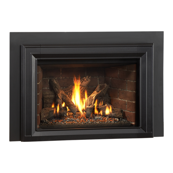
40"
1016
mm
Jøtul GI 535 DV IPI
New Harbor
Direct Vent Fireplace Insert
Installation and
Operation Instructions
INSTALLER: Leave this manual with the appliance.
CONSUMER: Retain this manual for future reference.
139775_R03 GI 535 DV IPI June 2016
WARNING:
!
FIRE OR EXPLOSION HAZARD. Failure to follow
safety warnings exactly could result in serious
injury, death, or property damage.
– Do not store or use gasoline or other
flammable vapors and liquids in the
vicinity of this or any other appliance.
– WHAT TO DO IF YOU SMELL GAS
• Do not try to light any appliance.
• Do not touch any electrical switch; do
not use any phone in your building.
• Immediately call your gas supplier
from a neighbor's phone. Follow the gas
supplier's instructions.
• If you cannot reach your gas supplier,
call the fire department.
– Installation and service must be
performed by a qualified installer, service
agency or the gas supplier.
– In the Commonwealth of Massachusetts,
a carbon monoxide (CO) detector shall
be installed in the same room as the
appliance.
This appliance may be installed in an aftermarket,
permanently located, manufactured home or
mobile home, where not prohibited by local codes.
This appliance is only for use with the types of gas
indicated on the rating plate. A conversion kit is
supplied with the appliance.
DANGER
!
A barrier designed to reduce the burn hazard
from the glass viewing area is provided with this
appliance and shall be installed for the protection
of children and other at-risk individuals.
HOT GLASS WILL
CAUSE BURNS
.
DO NOT TOUCH GLASS
UNTIL COOLED.
NEVER ALLOW CHILDREN
TO TOUCH GLASS.
1
Advertisement
Table of Contents

Related Manuals for Jøtul Jøtul GI 535 DV IPI New Harbor


Summary of Contents for Jøtul Jøtul GI 535 DV IPI New Harbor
- Page 1 139775_R03 GI 535 DV IPI June 2016 WARNING: FIRE OR EXPLOSION HAZARD. Failure to follow safety warnings exactly could result in serious 40” injury, death, or property damage. 1016 – Do not store or use gasoline or other flammable vapors and liquids in the vicinity of this or any other appliance.
- Page 2 139775_R03_GI 535 DV IPI June 2016 THIS OWNER’S MANUAL PROVIDES INFORMATION TO Installation Requirements ENSURE SAFE INSTALLATION AND EFFICIENT, DEPENDABLE for the Commonwealth of OPERATION OF YOUR FIREPLACE INSERT. PLEASE READ Massachusetts THESE INSTRUCTIONS IN THEIR ENTIRETY AND MAKE THEM AVAILABLE TO ANYONE USING OR SERVICING THIS GAS THIS PRODUCT MUST BE INSTALLED BY INSERT.
-
Page 3: Table Of Contents
139775_R03 GI 535 DV IPI June 2016 Table of Contents 1.0 Unpacking the Fireplace Insert 1. Thoroughly inspect the appliance for shipping damage and 1. Unpacking the Fireplace ......3 immediately contact the dealer if any is found. 2. Specifications ..........4 2. -
Page 4: Specifications
139775_R03_GI 535 DV IPI June 2016 Jøtul GI 535 DV IPI Direct Vent Gas Fireplace Insert Manufactured and Distributed by: Jøtul North America Gorham, Maine USA Jøtul AS Fredrikstad, Norway 2.0 Specifications Accessories Input Rates: • Traditional Red Brick Panel Kit ..........#157877 Natural Gas •... -
Page 5: General Information
139775_R03 GI 535 DV IPI June 2016 3.0 General Information 6. Do not operate the fireplace with the glass front THIS HEATER MUST BE INSTALLED AND removed, cracked, scratched, or broken. Replacement MAINTAINED BY A QUALIFIED SERVICE AGENCY. of the glass should be done by a licensed or qualified DO NOT ATTEMPT TO ALTER OR MODIFY service person. -
Page 6: Safety Information
139775_R03_GI 535 DV IPI June 2016 4.0 Safety Information Due to the high operating temperatures this appliance should be located out of traffic and away from Electrical Hazards furniture, draperies, etc. Maintain proper clearance to combustible mantels and fireplace trim. Be aware of electrical wiring locations Children and adults should be alerted to the hazards of high surface temperatures and should stay away to... -
Page 7: Installation
139775_R03 GI 535 DV IPI June 2016 Leg Leveling Note: This appliance is equipped with four leveling bolts; the front two 20 3/4” 527 mm are adjusted from inside the firebox, and the rear bolts are Air Inlet adjusted by tipping the firebox and unscrewing them from the Exhaust Outlet base. -
Page 8: Fireplace Requirements
139775_R03_GI 535 DV IPI June 2016 5.1 Fireplace Requirements 5.2 Clearance Requirements This appliance is approved for installation into a solid The following clearances and hearth specifications are fuel-burning, factory-built fireplace, or a code-approved, the minimum requirements for installing this appliance solid fuel-burning masonry fireplace with a tile flue into a solid fuel-burning fireplace. -
Page 9: Clearances
139775_R03 GI 535 DV IPI June 2016 NOTE - Raised Hearth: Forward hearth protection may be reduced by two inches (5.08 cm) for every inch of fireplace floor elevation. Fig. 5.4. Hearth Extension Forward / Inches Figure 5.4. Hearth reduction slope. 5.4 Mantel and Ceiling Clearances Measure clearances from the finished floor of the fireplace 12”... -
Page 10: Vent Guidelines
139775_R03_GI 535 DV IPI June 2016 6.0 Vent Guidelines Vent Installation Procedure • All vent components must be installed in accordance with the terms of their listing and manufacturer’s This appliance must be vented through the chimney instructions. See the Appendix on page 39 for a by a pair of 3 inch flexible aluminum liners listed for listing of approved vent manufacturers. -
Page 11: Masonry Fireplaces
139775_R03 GI 535 DV IPI June 2016 6.1 Masonry Fireplace IMPORTANT NOTICE: INSTALLATION OF A HIGH-WIND TERMINATION CAP IS RECOMMENDED FOR ALL IPI APPLIANCES TO HELP INCREASE PERFORMANCE. 1. Measure height of the chimney to fireplace opening. Determine if both the intake and exhaust will be We Recommend: extended to the top of the chimney. -
Page 12: Factory-Built Fireplaces
139775_R03_GI 535 DV IPI June 2016 IMPORTANT NOTICE: 6.2 Factory-built Fireplace INSTALLATION OF A HIGH-WIND TERMINATION CAP IS RECOMMENDED FOR ALL IPI APPLIANCES TO HELP INCREASE PERFORMANCE. IMPORTANT: We Recommend: BEFORE STARTING THIS INSTALLATION, MAKE SURE THAT • ICC EXCEL DIRECT - Use TM-CT3 with TM-CTS Cap Shield A GAS LINE CAN BE INSTALLED OR IS INSTALLED TO THE •... -
Page 13: Vent Connection
139775_R03 GI 535 DV IPI June 2016 6.3 Vent Connection Prefabricated Fireplace Vent Procedure Wear Safety Gloves! 1. Measure height of the chimney to fireplace Test fit the firebox in its final position to confirm it is opening. Determine if both the intake and level and plumb before connection to the vent system. -
Page 14: Fireplace Assembly
139775_R03_GI 535 DV IPI June 2016 7.0 Fireplace Assembly INSTALLATION OF A T-HANDLE GAS COCK IS REQUIRED IN MASSACHUSETTS IN COMPLIANCE Before beginning final assembly, push the insert into WITH CODE 248 CMR. the fireplace and adjust the leveling bolts located at each corner as appropriate to achieve a level and plumb installation. - Page 15 139775_R03 GI 535 DV IPI June 2016 REQUIRED INLET GAS PRESSURES (inches water column) NATURAL GAS 5.0 WC 7.0 WC Figure 7.4. PROPANE 11.0 WC 14.0 WC Pressure test points. REQUIRED MANIFOLD PRESSURES Inlet Manifold (inches water column) NATURAL GAS 1.6 WC 3.5 WC PROPANE...
-
Page 16: Fuel Conversion
139775_R03_GI 535 DV IPI June 2016 CAUTION: 7.3 Fuel Conversion WEAR SAFETY GLOVES WHILE WORKING WITHIN THE FIREBOX. 7.3.1 Fuel Conversion Procedure NOTE: IN ORDER TO ACCESS THE STEPPER MOTOR COMPONENTS, COMPLETE THE FUEL CONVERSION 1. Turn off the gas supply and disconnect electrical power to PROCEDURE BEFORE PLACING THE INSERT WITHIN the appliance. - Page 17 139775_R03 GI 535 DV IPI June 2016 Figure 7.6. Fuel Conversion Components. Pilot Assembly Rear Burner Injector Rear Burner Air Shutter Cable Front Burner Injector Front Burner Air Shutter Cable Air Shutter Adjustor Trays PILOT HOOD MUST BE ORIENTED TO Pilot Hood PROJECT FLAME DIRECTLY FORWARD...
-
Page 18: High Altitude Adjustment
139775_R03_GI 535 DV IPI June 2016 7.4 High Altitude Adjustment When installing this appliance at altitude above 2000 CAUTION: WEAR SAFETY GLOVES WHILE feet, it is necessary to compensate for the thinner air WORKING WITHIN THE FIREBOX. (less volume of air per cubic foot). Higher altitudes affect the atmospheric pressure and heat value of gaseous JØTUL ORIFICE... -
Page 19: Final Positioning
139775_R03 GI 535 DV IPI June 2016 7.5 Final Positioning 1. Clean the Fireplace. Use a vacuum to thoroughly clean all debris from the firebox. This will eliminate the potential for the insert fans to blow dust and debris back into the room. 2. -
Page 20: Reflective Glass Panel Kit
139775_R03_GI 535 DV IPI June 2016 7.7 Install Optional Reflective Glass Panels 157879 Reflective Glass Kit Tools Required • Left Panel - 225908 Flat Head Screwdriver • Right Panel - 225909 Pliers • Rear Panel - 225910 Safety Glasses • Side Panel Shelf, (2) - 225929 •... -
Page 21: Log Set Installation
139775_R03 GI 535 DV IPI June 2016 7.8 Install the Log Set NOTE: Install the optional Brick Panels before installing the Log Set. Install the log set in the order presented here. Fig. 7.21 shows the final arrangement. Use the rock wool fibers from the Miscellaneous Hardware bag to simulate glowing embers. - Page 22 139775_R03_GI 535 DV IPI June 2016 Figure 7.22 Figure 7.19. Engage pockets in the underside of Right Lower Log #5 with the adjacent blocks on the burner base. WARNING: FREQUENTLY INSPECT THE PILOT AREA AND KEEP IT CLEAR OF MISPLACED LOGS OR DEBRIS.
-
Page 23: Backer Plate Installation
139775_R03 GI 535 DV IPI June 2016 NOTE: COMPLETE FUEL CONVERSION, HIGH ALTITUDE ADJUSTMENT, AND BRICK OR GLASS PANEL INSTALLATION BEFORE ASSEMBLING BACKER PLATES. FOR #5 Figure 7.23 7.9 Standard Backer Plate Backer Plate installation. Installation The standard Backer plates each incorporate hanger brackets to which the Front Cast Iron Overlay Assembly will be attached. -
Page 24: Hidden Hanger Bracket
139775_R03_GI 535 DV IPI June 2016 7.11 Hidden Hanger Bracket Installation The Hidden Hanger Brackets are used for installations that do not require the standard Backer Plate. (They are included with Trimmable Surround Kits.) The brackets provide a means of attachment for the Front Cast Iron Overlay assembly. -
Page 25: Operation
139775_R03 GI 535 DV IPI June 2016 8.0 Operation 8.1 Initial System Check and WARNING: General Operation READ AND UNDERSTAND ALL OPERATING INSTRUCTIONS BEFORE ATTEMPTING TO OPERATE THIS APPLIANCE. DO NOT ALLOW ANYONE TO This appliance is designed to be operated with use of the Remote OPERATE THIS APPLIANCE WHO HAS NOT READ AND Control System. - Page 26 139775_R03_GI 535 DV IPI June 2016 7. Condensation will develop on the glass upon each lighting of the appliance. This “fog” will dissipate as the glass heats. Using CPI mode will minimize condensation. 8. IMPORTANT: It will be necessary to clean the glass after the first few fires.
-
Page 27: Fireplace Operation
139775_R03 GI 535 DV IPI June 2016 8.2 Fireplace Operation 8.2.1 Burner Switch • ON : Power is available to the Burner(s) only. They will ignite at the last previous flame level setting. • REMOTE : Power is available for all appliance features. •... -
Page 28: Remote Control Functions
139775_R03_GI 535 DV IPI June 2016 8.3 Proflame 2 Remote Control 8.3.1 Features Overview Pilot Assembly The pilot assembly consists of a pilot hood, electrode, and The Proflame 2 Integrated Fireplace Control (IFC) module a flame sensor. The electrode sends a spark to the pilot incorporates electronic remote control of the Jøtul hood which ignites the gas. - Page 29 139775_R03 GI 535 DV IPI June 2016 8.3.2 Remote Control Functions IFC / Transmitter Mode Synchronization 1. Install three fresh AAA batteries into the Transmitter. Pilot Mode Control 2. Set the fireplace Burner Switch to REMOTE. The IPI/CPI functionality will be fully controlled by ...
- Page 30 139775_R03_GI 535 DV IPI June 2016 8.3.3 Transmitter Key Control Temperature Indication Display With the transmitter in the OFF position, press the Thermostat Key and the Mode Key at the same time. The display screen will show the current room temperature cycling between Fahrenheit and Celsius indicators each time the keys are pressed Figure 8.8.
- Page 31 139775_R03 GI 535 DV IPI June 2016 Room Thermostat (Transmitter Operation) The Remote Control can operate as a room thermostat. Room Temperature The thermostat can be set to a desired temperature to control the comfort level in a room. To activate this function, press the Thermostat Key. The ...
-
Page 32: Maintenance
139775_R03_GI 535 DV IPI June 2016 9.0 Maintenance 9.2 Accent Lamp Replacement CAUTION: THE IGNITION SYSTEM OF THIS APPLIANCE CARRIES 1. Remove the cast iron overlay assembly, backer plate, LIVE VOLTAGE. ALWAYS TURN OFF THE GAS SUPPLY and glass frame., TO THE INSERT AND DISCONNECT THE POWER 2. -
Page 33: Glass Care And Replacement
139775_R03 GI 535 DV IPI June 2016 9.4 Glass Care Moisture condensation is a normal occurrence with gas appliances and particulate accumulation may appear on the inside surface to the glass. Use a dampened, soft cloth to clean the glass and polish with a dry, soft towel. Specially-formulated ceramic glass cleaner may also be used. -
Page 34: Illustrated Part Breakdowns
139775_R03_GI 535 DV IPI June 2016 10.0 Jøtul GI 535 DV IPI Replacement Parts ONLY USE REPLACEMENT PARTS PROVIDED BY AN AUTHORIZED JØTUL DEALER. Figure 10.1 Controls components, right side compartment. No. Part Number Description 225797 Controls, Skid Plate 117917 Screw, HWH SMA #8 x 1/2”... - Page 35 139775_R03 GI 535 DV IPI June 2016 Figure 10.2. SHEET Valve Train components, left side compartment. 1 OF 1 SCALE 0.375 NG DATE: 8/4/15 No. Part Number Description No. Part Number Description 225676 Flex Tube, Main Gas - 5/16” OD x 24” 225527 Valve Heat Shield 129464...
- Page 36 139775_R03_GI 535 DV IPI June 2016 Figure 10.3 Internal firebox components. No. Part Number Description No. Part Number Description - not illustrated 225706 Baffle 225840 Orifice, Left, 1.95 mm, 0 - 2000 ft. / NG 117968 Hex Nut, M6 Serrated Flange 129407 Orifice, Left,#48, 2001 - 4500 ft.
- Page 37 104676 SURROUND LEG RIGHT 104677 PLINTH 225783 HANGING BRACKET 139775_R03 GI 535 DV IPI June 2016 225785 ADJ. SCREEN RETAINER 225786 TOP CORNER BRACKET 225784 SCREEN RETAINER TOP 117978 M6 X 10 BUTTON HEAD 225787 BOTTOM CORNER BRACKET 225788 BOTTOM SHADE 225782 BULK HEAD, SCREEN ADJ.
- Page 38 139775_R03_GI 535 DV IPI June 2016 Figure 10.5. Blower Assembly Figure 10.6. Glass components. No. Part Number Description No. Part Number Description 225846 Blower Cover 129124 Gasket, Fiber Glass w/ Graphite, .25” x 1.25 “, 7.3 ft. 117917 Screw, HWH SMA 8 x 1/2 SL Blk Oxide 157894 Glass Panel w/ Gasket 225861...
-
Page 39: Approved Vent Manufacturers
139775_R03 GI 535 DV IPI June 2016 11.0 Appendix 11.1 Approved Vent Manufacturers This appliance is approved for use with vent systems from the following manufacturers: • M&G DuraVent, Inc. (Direct Vent Pro Series) • American Metal Products (Amerivent) • Security Chimneys International, Ltd. (Secure Vent) •... -
Page 40: Proflame 2 Wiring Diagram
139775_R03_GI 535 DV IPI June 2016 11.3 Proflame 2 Wiring Diagram CAUTION: ALWAYS DISCONNECT ELECTRICAL POWER WHEN SERVICING THIS APPLIANCE. LABEL ALL WIRES PRIOR TO DISCONNECTION WHEN SERVICING THE CONTROLS. WIRING ERRORS CAN CAUSE IMPROPER AND DANGEROUS OPERATION. ALWAYS VERIFY PROPER OPERATION AFTER SERVICING THE APPLIANCE. -
Page 41: Warranty Statement
139775_R03 GI 535 DV IPI June 2016 11. 4 Jøtul GI 535 DV IPI 2) Damage due to incorrect installations not in conformance with the Fireplace Insert Limited Warranty installation instructions contained in this owner’s manual or local and/or national fire and building regulations. 3) Damage due to service performed by an installer, service agency or gas Effective January 1, 2013. - Page 42 139775_R03_GI 535 DV IPI June 2016 This page is intentionally blank.
-
Page 43: Lighting Instructions
139775_R03 GI 535 DV IPI June 2016 LIGHTING INSTRUCTIONS FOR YOUR SAFETY, READ BEFORE LIGHTING. WARNING: IF YOU DO NOT FOLLOW THESE INSTRUCTIONS EXACTLY, A FIRE OR EXPLOSION MAY RESULT CAUSING PROPERTY DAMAGE, PERSONAL INJURY, OR LOSS OF LIFE. A. This appliance is equipped with an ignition device which automatically lights the pilot. Do not try to light the pilot by hand. - Page 44 139775_R03_GI 535 DV IPI June 2016 This appliance must be installed in conformance with local and national building regulations. Before beginning the installation, it is important that the these instructions be carefully read and understood. Jøtul maintains a policy of continuous product development. Consequently, products may differ in specification, color or type of accessories from those illustrated or described in various publications.
Need help?
Do you have a question about the Jøtul GI 535 DV IPI New Harbor and is the answer not in the manual?
Questions and answers