
Related Manuals for TechnipFMC Smith Meter AccuLoad IV


Summary of Contents for TechnipFMC Smith Meter AccuLoad IV
- Page 1 Smith Meter ® AccuLoad IV Installation & Maintenance Manual Bulletin MN06201 Issue/Rev. 0.2 (3/21) March 2021...
- Page 2 Important All information and technical specifications in this document have been carefully checked and compiled by the author; however, we cannot completely exclude the possibility of errors. TechnipFMC is always grateful to be informed of any errors; contact us at TechnipFMC.com.
-
Page 3: Table Of Contents
Network Meter Block Installation, Operation, & Maintenance Manual Contents 1 Introduction ........... 1 1.1 Product Description . - Page 4 Network Meter Block Installation, Operation, & Maintenance Manual 3.3.2 Special Conditions for Safe Use ........... 18 3.3.3 Cable Entries.
- Page 5 Network Meter Block Installation, Operation, & Maintenance Manual 4.2.2 Genesis ..............47 4.2.3 Universal Pulse Transmitter .
-
Page 6: Introduction
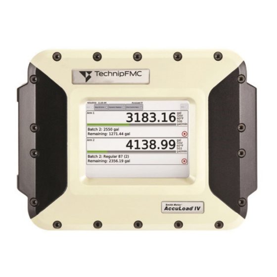
AccuLoad IV Installation & Maintenance Manual 1 Introduction This manual provides guidance for the electrical installation and general maintenance of the Smith Meter AccuLoad IV. When installed following the guidelines contained in this manual, the AccuLoad should provide many years of safe, accurate, and reliable use. This manual addresses the requirements specific to the AccuLoad IV and it is assumed that the installation designers and fabricators are familiar with the applicable industrial facility construction standards specific to the particular facility. - Page 7 AccuLoad IV Installation & Maintenance Manual Figure 1: AccuLoad IV ST Introduction...
-
Page 8: Accuload Iv Qt
AccuLoad IV Installation & Maintenance Manual Figure 2: AccuLoad IV ST Dimensions 1.1.1.2 AccuLoad IV QT The Quad Touch Screen (QT) model has the following specifications: • Explosion-proof enclosure • Up to six-arm operation • Up to six single- or dual-pulse product meter inputs •... - Page 9 AccuLoad IV Installation & Maintenance Manual Figure 3: AccuLoad IV QT Introduction...
-
Page 10: Accuload Iv N4
AccuLoad IV Installation & Maintenance Manual Figure 4: AccuLoad IV QT Dimensions 1.1.1.3 AccuLoad IV N4 The NEMA 4 (N4) model has the following specifications: • 304 stainless steel, NEMA 4X-rated enclosure • One-or two-arm operation • Up to four single- or dual-pulse product meter inputs •... - Page 11 AccuLoad IV Installation & Maintenance Manual Figure 5: AccuLoad IV N4 Introduction...
-
Page 12: Accuload Iv Sa
AccuLoad IV Installation & Maintenance Manual Figure 6: AccuLoad IV N4 and MMI Dimensions 1.1.1.4 AccuLoad IV SA The Split Architecture (SA) model is comprised of one field control module (FCM) and one or two man- machine interfaces (MMI). The FCM contains the I/O control electronics that are connected to meters, valves, permissives, and other hardware;... - Page 13 AccuLoad IV Installation & Maintenance Manual • Up to 24 single- or dual-pulse product meter inputs • Up to 56 additive meter inputs with the A4I I/O module or, with the remote A4I module, up to 96 additive meter inputs The MMI has an optional integrated card reader, indicator lights, and stop button.
- Page 14 AccuLoad IV Installation & Maintenance Manual Figure 8: AccuLoad IV SA FCM Introduction...
-
Page 15: Electronic Modules
AccuLoad IV Installation & Maintenance Manual 1.1.2 Electronic Modules The AccuLoad IV has the following standard and optional electronic modules. Table 1: Electronic Modules by Model explains which modules are standard or optional for each AccuLoad model; Table 2: Model Functions and Capacities provides details about each module. -
Page 16: Warnings And Precautions
AccuLoad IV Installation & Maintenance Manual 1.2 Warnings and Precautions Before you begin installing the AccuLoad, please read all of the following warnings and cautions to the reduce the risk of injury, equipment damage, or malfunction. WARNING: The AccuLoad should never be relied upon to act as the primary safety system control for the flow valve and pump controls (such as emergency stop, overfill, and ground protection). -
Page 17: Rf Radiation
AccuLoad IV Installation & Maintenance Manual “Warning: Clean display with a damp cloth only.” This is to ensure that stray static charges are not built up on the surface that could lead to a static discharge. • Special care must be taken with shielding termination to ensure signal integrity. See Section 3.1: General Electrical Installation Requirements for more information. -
Page 18: Pre-Installation Considerations
In areas of high humidity (tropical) or with varying temperature swings, it is recommended to place desiccant packs (TechnipFMC part number 647001443) inside of the enclosures, and to maintain these while in service. -
Page 19: Electrical Installation Considerations
AccuLoad IV Installation & Maintenance Manual • A solid bracket (rear- or bottom-mount) should be used to support the AccuLoad. Refer to the AccuLoad IV specifications (SS06200) for the weight and mounting dimensions. • The location and the height of the AccuLoad should easily permit operation of the front touch screen and allow for a near-perpendicular viewing angle to minimize parallax effects. - Page 20 AccuLoad IV Installation & Maintenance Manual • Two separate AC circuits must be provided from the breaker panel. One circuit should supply isolated power to the AccuLoad’s electronics (instrument power). The second circuit should supply power to external devices (Section 3.6.1: AC Input Power).
-
Page 21: Installation
AccuLoad IV Installation & Maintenance Manual 3 Installation The general steps in the installation process are to physically mount the AccuLoad, electronically connect it to work with associated equipment, and then configure it to suit its specific operational and measurement environment. -
Page 22: Atex- And Iecex-Approved Installations
AccuLoad IV Installation & Maintenance Manual • Sufficient slack should be provided for the wiring in the AccuLoad to permit easy removal of the boards. With sufficient slack, the terminal blocks can be removed and laid out of the way so that the boards can be replaced without removing individual wires. -
Page 23: Cover Fasteners
Special conditions for safe use include: • Cables and cable glands should be suitable for operation at 81 °C. • For information about the dimensions of flame-proof joints, contact TechnipFMC at the address provided on the back page this manual. Installation... -
Page 24: Cable Entries
AccuLoad IV Installation & Maintenance Manual 3.3.3 Cable Entries All cable entries must meet the requirements of ABNT NBR IEC 60079-1, summarized as follows: • Any installation accessories used in the cable entries (such as cable glands, adapters, or bushings) must be Ex d certified. -
Page 25: Electronic Layouts And Connections
AccuLoad IV Installation & Maintenance Manual Each MMI is connected to its MMIs by Ethernet or serial cables. Figure 9: AccuLoad IV Split Architecture Units Optional Ethernet The FCM unit can be installed at a location that is convenient to service personnel. The MMI units can be installed for convenient access by drivers. -
Page 26: Mmi Units
AccuLoad IV Installation & Maintenance Manual Additionally, a factory-wired DC distribution block is located on the bottom left corner of the FCM. One distribution terminal block is provided for each A4M board in the FCM. The input to this terminal block is factory wired to its associated board set and provides 12 separate slots to supply 24 VDC to external equipment, such as MMI units, external meter transmitters, and DC digital inputs. -
Page 27: Thmi Module
AccuLoad IV Installation & Maintenance Manual The MMI requires power and Ethernet communications from the FCM. The power connections can be made with AC or DC supplies when made to the appropriate terminals. The Ethernet connection is made between the THMI module and the configured board set in the FCM enclosure. Figure 12: Model SA MMI components + 24 VDC Factory Wired... -
Page 28: A4M Board
AccuLoad IV Installation & Maintenance Manual The following figure identifies the wiring connections on the THMI electronic module. Figure 13: THMI Module Connections 1 V+ 12/24 V 2 GND 3 GND ETH1 3.5.4 A4M Board The main input/output board for the AccuLoad IV is an A4M board available for the ST, QT, and N4 models, as well as the SA model’s MMI component. - Page 29 AccuLoad IV Installation & Maintenance Manual The replaceable parts on the A4M board are the power fuse, AC digital output relays, and the analog I/O modules. Refer to the AccuLoad IV parts list (PO06200) for details. Figure 14: A4M Board Layout Analog I/O Modules ETH3 ETH2...
-
Page 30: A4M I/O Connections
AccuLoad IV Installation & Maintenance Manual 3.5.4.1 A4M I/O Connections The following drawing details the A4M board’s I/O connections. Figure 15: A4M Board Connections TBE5 RTD + SIG + SIG - RTD - Pulse In 1 Enet Enet RTD + TBE2 Pulse In 2 SIG +... -
Page 31: A4M Special I/O Considerations
AccuLoad IV Installation & Maintenance Manual Table 7: A4M I/O Index Numbering AccuLoad Configuration Index Terminals Type of I/O Number TBK4 DC digital input Digital inputs 1 through 3 TBK4 Pulse output Pulse output 1 TBK5 DC digital output Digital outputs 1 through 3 or pulse outputs 3 through 5 TBK5 Pulse output... -
Page 32: A4M Sw2 Dip Switch Settings
AccuLoad IV Installation & Maintenance Manual Table 9: A4M S1 DIP Switch Settings Switch Setting S1-6 Clear pairing information S1-7 Off for ST, QT, and N4 models Board set selector for SA model board set (see Section 3.7.1.4: SA Board Set IP Addresses) S1-8... - Page 33 AccuLoad IV Installation & Maintenance Manual The replaceable parts on the A4B board are the power fuse and the AC digital output relays. Refer to the AccuLoad IV parts list (PO06200) for details. Figure 16: A4B Board Layout LMOD1 SSR1 SSR2 SSR3 SSR4...
-
Page 34: A4B I/O Index Numbering
AccuLoad IV Installation & Maintenance Manual 3.5.5.1 A4B I/O Index Numbering The following table provides details about configuring the A4B board’s I/Os. Table 11: A4B I/O Index Numbering Terminals Type of I/O AccuLoad Configuration Index Number AC digital output Digital outputs 26 through 30 AC digital output Digital outputs 20 through 25 TB10... -
Page 35: A4I I/O Connections
AccuLoad IV Installation & Maintenance Manual Up to two A4I modules can be connected to an A4M board and can either be mounted inside the AccuLoad enclosure or in a separate external enclosure. For any additive meters connected to pulse inputs located on the A4I, the digital outputs controlling the associated pump and solenoid valve must be located on the same A4I module. - Page 36 AccuLoad IV Installation & Maintenance Manual Firmware updates are not available over serial connections in the A4I. The following drawing shows the A4I board’s I/O connections. Figure 19: A4I Connections +V Out Enet Enet Inj Pulse/DC In 1 Out 1-Out 10 Common +V Out Inj Pulse/DC In 2...
-
Page 37: A4I I/O Index Numbering
AccuLoad IV Installation & Maintenance Manual Table 15: A4I Switch Settings Switch Setting S1-1 Factory Use S1-2 OFF = Address 100 ON = Address 200 S1-3 OFF = Band 9600 ON = Band 38,400 S1-4 OFF = RS 232 ON = RS 485 S1-5 OFF = Address 100 ON = Address 200... - Page 38 AccuLoad IV Installation & Maintenance Manual Table 16: First Optional A4I I/O Index Numbering Terminal Type of I/O AccuLoad Configuration Index Number Block Serial communication port Inj 5 in or DC In 24 – Pin 2 Inj 6 in or DC In 25 – Pin 5 RS485 Inj 7 in or DC In 26 –...
-
Page 39: A4I Dip Switch Settings
AccuLoad IV Installation & Maintenance Manual Table 17: Second Optional A4I I/O Index Numbering Terminal Type of I/O AccuLoad Configuration Index Number Block Serial communication port Inj 15 in or DC In 34 – Pin 2 Inj 16 in or DC In 35 – Pin 5 Inj 17 RS485 in or DC In 36 –... -
Page 40: General Wiring Information
AccuLoad IV Installation & Maintenance Manual 3.6 General Wiring Information During initial installation of the AccuLoad and anytime an electronic module is installed, the two calibration numbers (Cal 1 and Cal 2) written on the top of the module should be configured in AccuMate for AccuLoad IV to ensure optimum accuracy. -
Page 41: Dc Instrument Power
AccuLoad IV Installation & Maintenance Manual Figure 22: Example of AC Wiring for a Typical AccuLoad Terminal Board Key 3.6.2 DC Instrument Power The AC instrument power is connected to the A4M module, which produces 24 VDC power for the standard modules in the AccuLoad (THMI and A4B). -
Page 42: Grounding
AccuLoad IV Installation & Maintenance Manual Figure 23: DC Power Wiring on ST, QT, and N4 Models A4M Module TBE4 Factory wired to AccuLoad internal modules +24 VDC To meter transmitters, remote A4I etc. DC GND Factory wired to AccuLoad internal modules 3.6.3 Grounding The AccuLoad must be properly grounded to ensure safe and reliable operation. -
Page 43: Analog I/O Modules
AccuLoad IV Installation & Maintenance Manual • Dual Channel with Integrity—Four pulse inputs receive two pulses streams and two inverted pulse streams from the meter. This enables the AccuLoad to detect the direction of flow and meter connection problems, including when both pulse streams are inactive. For each of the above meter pulse modes, the signal on the input to the AccuLoad must be less than 1 volt for a minimum of 80 microseconds and then transition to greater than 5 volts and remain above 5 volts for a minimum of 80 microseconds to qualify as a valid pulse (as shown in the following graph). -
Page 44: Typical Wiring Diagrams
AccuLoad IV Installation & Maintenance Manual Figure 26: Analog I/O Modules Sockets Analog Module Set Cal 1 and Cal 2 parameters to these Alignment Pins Mounting Screw values in AccuLoad analog configuration Top View Side View CAUTION: Before inserting or removing any analog module, first ensure that all associated circuits are de-energized. - Page 45 AccuLoad IV Installation & Maintenance Manual Figure 29: AC Digital Output AccuLoad AC Power Supply Alarm, Valve, etc. Receiving Device Figure 30: DC Digital Input AccuLoad External DC Wiring +24 VDC from A4M TBE4 10, 11, or 12 IN X+ IN X- DC Ground from A4M TBE4 13, 14, or 15...
- Page 46 AccuLoad IV Installation & Maintenance Manual Figure 32: RTD Temperature Probe Analog Inputs AccuLoad Resistance Temperature Probe RTD + SIG + Black SIG - Black RTD - A4M TBE6 13, 14, or 15 Figure 33: Active 4-20 mA Analog Inputs AccuLoad IV A4M Terminal Block TB5 RTD +...
-
Page 47: Communications Wiring
AccuLoad IV Installation & Maintenance Manual Figure 36: External Counter Wiring AccuLoad External Meter Pulse Wiring A4M +24V TBE4 10, 11, or 12 IN X+ IN X- Open Collector Meter Output A4M GND TBE4 13, 14, or 15 For pulse transmitters requiring 12 VDC (such as GPST), install the P2412 converter. See the AccuLoad Preset Accessory P2412 Converter Installation manual (MN06117) for details. -
Page 48: St And N4 Model Ethernet Connections
AccuLoad IV Installation & Maintenance Manual Figure 38: Recommended Network Strategy AccuLoad AccuLoad Process Database Data Historian Firewall Firewall Automation Server Corporate Internet Industrial Control Network 3.7.1.1 ST and N4 Model Ethernet Connections Ethernet connections for the ST and N4 models are shown in the following diagram. Figure 39: Ethernet Connections in AccuLoad ST and N4 Models ETH 1 (reserved) THMI... -
Page 49: Sa Model Ethernet Connections
AccuLoad IV Installation & Maintenance Manual 3.7.1.3 SA Model Ethernet Connections Ethernet is used for communication between the SA model’s FCM and MMI units, as shown in the following diagram. On each MMI’s THMI board, the Ethernet cable connects the ETH1 RJ45 jack to a board set in the FCM. -
Page 50: Serial Communications
AccuLoad IV Installation & Maintenance Manual For new equipment, these DIP switches are set at the factory and should not need adjustment during installation. However, any time a module is moved or replaced, the IP address must be reset according to the table below. -
Page 51: Pulse Outputs
AccuLoad IV Installation & Maintenance Manual Figure 44: RS-232 Serial Wiring Figure 45: Multi-Drop RS-232 Serial Wiring RX TX GND RX TX GND 3.9 Pulse Outputs The AccuLoad can be configured to provide up to five pulse outputs, as detailed in the following table. Table 22: Pulse Output Configurations Pulse Outputs Configurations... -
Page 52: Meter I/O Connections
AccuLoad IV Installation & Maintenance Manual 4 Meter I/O Connections 4.1 I/O Index Numbering When configuring the AccuLoad, I/O points are referred to by their index number. 4.2 Meter Connection Details 4.2.1 PRIME 4 Meter The AccuLoad uses the I/O connection points in the following table to connect to Smith Meter PRIME 4 meters. -
Page 53: Universal Pulse Transmitter
AccuLoad IV Installation & Maintenance Manual 4.2.3 Universal Pulse Transmitter The AccuLoad uses the I/O connection points in the following table to connect to the Smith Meter Universal Pulse Transmitter (UPT). Table 25: UPT Connections AccuLoad Connections UPT Connections Pulse input A plus Terminal 5 (signal A output) Pulse input B plus (dual-pulse only) Terminal 3 (signal B output);... -
Page 54: Preamplifier
AccuLoad IV Installation & Maintenance Manual 4.2.5 PA-6 Preamplifier The AccuLoad uses the I/O connection points in the following table to connect to the Smith Meter PA-6 Preamplifier. Table 27: PA-6 Preamplifier Connections AccuLoad Connections PA-6 Connections Pulse input A plus Terminal 3 (signal A output) Pulse input minus –... -
Page 55: Meter Input Wiring
AccuLoad IV Installation & Maintenance Manual Because the pulse input circuitry of the AccuLoad requires the input pulse OFF voltage to be less than 1 volt (and the ON voltage to be more than 5 volts), it is important that the Line Monitoring function on the Promass 84 be disabled when connecting the Promass 84 to the AccuLoad. -
Page 56: Meter Inputs For St And N4 Models
AccuLoad IV Installation & Maintenance Manual The tables in the following sections detail the pulse input assignments made by the AccuLoad for each of the possible number of product meters. Any pulse inputs not required for connection of the product meters are available to be configured for use as an additive meter or pulse densitometer. -
Page 57: Meter Inputs For Qt And Sa Models
AccuLoad IV Installation & Maintenance Manual Table 34: Three-Product Meters (AccuLoad Models ST and N4) In #1 In #2 In #3 In #4 In #5 In #6 In #7 In #8 Single Pulse Dual Pulse Dual pulse with integrity Table 35: Two-Product Meters (AccuLoad Models ST and N4) In #1 In #2 In #3... -
Page 58: Additive Meters And Digital Inputs
AccuLoad IV Installation & Maintenance Manual Table 39: Four-Product Meters (AccuLoad IV QT and SA Models) In #1 In #2 In #3 In #4 In #5 In #6 In #7 In #8 In #9 In #10 In #11 In #12 In #13 In #14 Single pulse Dual... -
Page 59: A4I Kit Retrofit Installation
AccuLoad IV Installation & Maintenance Manual The A4I module provides outputs to supply power to the additive meter. The voltage supplied is selectable (5, 12, or 24 VDC) using jumpers on the module. Figure 46: A4I Additive Meter Wiring AccuLoad A4M +24V TBE4 10, 11, or 12 External Prover... - Page 60 AccuLoad IV Installation & Maintenance Manual The following drawing shows the installation of the dual A4I board kit. Figure 48: Dual A4I Boards on A4M Board Complete the following steps to install one or two A4I boards onto the AccuLoad IV’s A4M board: 1.
- Page 61 AccuLoad IV Installation & Maintenance Manual 9. Connect an Ethernet cable as follows: • On QT models, connect an Ethernet cable from ETH2 on the A4I #1 board to ETH2 on the A4B board. • On ST and N4 models, connect an Ethernet cable from ETH2 on the A4I board to ETH3 on the A4M board.
- Page 62 AccuLoad IV Installation & Maintenance Manual 14. Connect the DC power supply wiring (red and black twisted pair) as shown below in Figure 49: A4M to Wiring: Figure 49: A4M to A4I Wiring Meter I/O Connections...
-
Page 63: Closing And Sealing The Enclosure
1. Inspect the door seal O-ring for damage and replace if damaged. The O-ring is not required to maintain the explosion-proof rating; however, it is required to maintain the IP 65 ingress protection rating. 2. Grease cover flange with petroleum jelly or TechnipFMC grease (part number 644886401) before attaching the cover to the housing. -
Page 64: Sealing The Enclosure
AccuLoad IV Installation & Maintenance Manual Figure 51: Cover Bolt Torque Pattern for AccuLoad IV Model QT Figure 52: Flame Path Verification 5.2 Sealing the Enclosure All AccuLoad enclosures can be sealed using standard seal wires. Closing and Sealing the Enclosure... -
Page 65: Sealing St And Qt Models
AccuLoad IV Installation & Maintenance Manual 5.2.1 Sealing ST and QT Models On the ST and QT models, the sealing wire is threaded through holes in two cover bolts, as shown in the following drawings. Figure 53: AccuLoad Model ST Sealing Seal Wire Cross drilled... -
Page 66: Maintenance
(no cracks, etc.). If the O-ring is defective, replace it to maintain environmental protection. Grease the cover flange with petroleum jelly or Super Lube Multi-Purpose Synthetic Grease with Syncolon (TechnipFMC part number 644886-401) before reattaching the cover to the housing. •... -
Page 67: St And Qt Models In Special Environments
Enclosures located in corrosive environments are required to have a coating of petroleum jelly or TechnipFMC grease (part number 644886401) to flanged metal surfaces (including the flame path between the window and cover and the keypad cover) to offer a protective barrier and reduce the effects of exposure to wet, salty air. -
Page 68: Replacing The Clock Battery
AccuLoad IV Installation & Maintenance Manual 1. Carefully remove the existing screen protector by finding the edge of the plastic and, using a nylon screwdriver or similar tool, peeling back a corner of the screen protector until you can grasp and remove Avoid using metal screwdrivers, knife blades, or sharp tools that could scratch or crack the underlying glass. -
Page 69: Diagnostic Troubleshooting On A4M, A4B, And A4I Boards
AccuLoad IV Installation & Maintenance Manual a. Position the A4M board so the gold tab on the RTC Figure 56: Removing the Battery battery socket is pointing toward you. b. Using the flathead screwdriver supplied with your AccuLoad, press down on the battery on the right side of the gold tab and then gently pull it toward you. -
Page 70: Returning A Circuit Board Using A Return Merchandise Authorization (Rma)
AccuLoad IV Installation & Maintenance Manual Table 43: A4M, A4B, and A4I Diagnostic Codes Diagnostic Function Description Code Bootloader Errors A hardware failure has occurred in the Bootloader; the board must be replaced An upgrade error has occurred; retry the firmware update A firmware error has occurred;... -
Page 71: Related Publications
AccuLoad IV Installation & Maintenance Manual 7 Related Publications The following literature can be obtained from TechnipFMC Measurement Solutions Literature Fulfillment at Measurement.Fulfillment@TechnipFMC.com or online at info.smithmeter.com/literature/online_index.html. When requesting literature, please reference the appropriate title and document number, as follows: •... - Page 72 (i) is the property of TechnipFMC plc, (ii) is disclosed by TechnipFMC only in confidence, and (iii) except as TechnipFMC may otherwise permit in writing, is to be used, disclosed or copied only to the extent necessary for the evaluation and use thereof by the recipient.
Need help?
Do you have a question about the Smith Meter AccuLoad IV and is the answer not in the manual?
Questions and answers