
Related Manuals for TechnipFMC Proline Promass F 500


Summary of Contents for TechnipFMC Proline Promass F 500
- Page 1 MANUAL Proline Promass F 500 Coriolis Flowmeter EtherNet/IP Operating Instructions Manual BA01812O/06/EN/01.17 Valid as of version 01.00.zz (Device firmware) 71382414...
-
Page 2: Technical Support
All information and technical specifications in this documentation have been carefully checked and compiled by the author. However, we cannot completely exclude the possibility of errors. TechnipFMC is always grateful to be informed of any errors. Contact us on the website. -
Page 3: Table Of Contents
Proline Promass F 500 EtherNet/IP Table of contents Table of contents Transporting the product ....23 About this document ....6 5.2.1... - Page 4 Table of contents Proline Promass F 500 EtherNet/IP Special connection instructions ... . 65 Cyclic data transmission ....105 7.5.1...
- Page 5 Proline Promass F 500 EtherNet/IP Table of contents 11.4.4 Output values ....201 Repairs ......245 11.5 Adapting the measuring device to the process...
-
Page 6: About This Document
About this document Proline Promass F 500 EtherNet/IP About this document Document function These Operating Instructions contain all the information that is required in various phases of the life cycle of the device: from product identification, incoming acceptance and storage, to mounting, connection, operation and commissioning through to troubleshooting, maintenance and disposal. -
Page 7: Communication Symbols
Proline Promass F 500 EtherNet/IP About this document 1.2.3 Communication symbols Symbol Meaning Wireless Local Area Network (WLAN) Communication via a wireless, local network. Light emitting diode is off. Light emitting diode is on. Light emitting diode is flashing. 1.2.4... -
Page 8: Symbols In Graphics
About this document Proline Promass F 500 EtherNet/IP 1.2.6 Symbols in graphics Symbol Meaning 1, 2, 3, ... Item numbers , … Series of steps A, B, C, ... Views A-A, B-B, C-C, ... Sections Hazardous area Safe area (non-hazardous area) -
Page 9: Supplementary Device-Dependent Documentation
Proline Promass F 500 EtherNet/IP About this document Document type Purpose and content of the document Transmitter Brief Operating Guides you quickly to the 1st measured value - Part 2 Instructions The Transmitter Brief Operating Instructions are aimed at specialists with responsibility for commissioning, configuring and parameterizing the measuring device (until the first measured value). -
Page 10: Basic Safety Instructions
Basic safety instructions Proline Promass F 500 EtherNet/IP Basic safety instructions Requirements for the personnel The personnel for installation, commissioning, diagnostics and maintenance must fulfill the following requirements: ‣ Trained, qualified specialists must have a relevant qualification for this specific function and task. -
Page 11: Workplace Safety
Proline Promass F 500 EtherNet/IP Basic safety instructions WARNING Danger of breakage due to corrosive or abrasive fluids! ‣ Verify the compatibility of the process fluid with the sensor material. ‣ Ensure the resistance of all fluid-wetted materials in the process. -
Page 12: Product Safety
Basic safety instructions Proline Promass F 500 EtherNet/IP ‣ Use original spare parts and accessories from Endress+Hauser only. Product safety This measuring device is designed in accordance with good engineering practice to meet state-of-the-art safety requirements, has been tested, and left the factory in a condition in which it is safe to operate. -
Page 13: Protecting Access Via A Password
Proline Promass F 500 EtherNet/IP Basic safety instructions the motherboard). When hardware write protection is enabled, only read access to the parameters is possible. Hardware write protection is disabled when the device is delivered → 194. 2.7.2 Protecting access via a password Different passwords are available to protect write access to the device parameters or access to the device via the WLAN interface. -
Page 14: Access Via Web Server
Basic safety instructions Proline Promass F 500 EtherNet/IP 2.7.4 Access via Web server The device can be operated and configured via a Web browser with the integrated Web server (→ 89). The connection is via the service interface (CDI-RJ45), the connection for EtherNet/IP signal transmission (RJ45 connector) or the WLAN interface. -
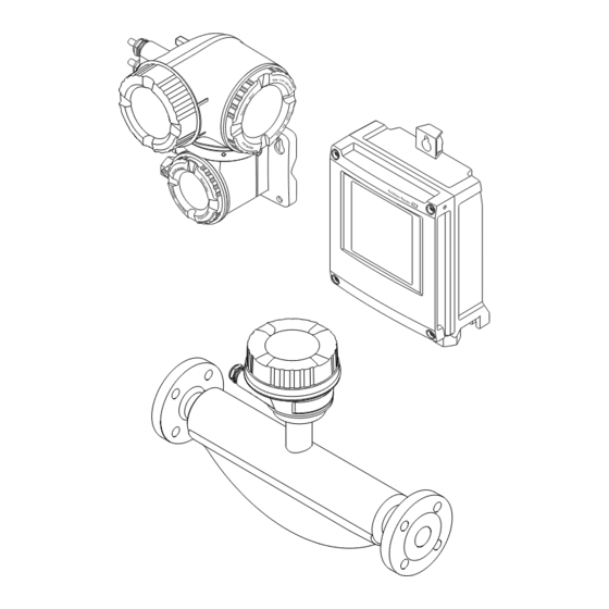
Page 15: Product Description
Proline Promass F 500 EtherNet/IP Product description Product description The measuring system consists of a transmitter and a sensor. The transmitter and sensor are mounted in physically separate locations. They are interconnected by one connecting cable(s). Product design Two versions of the transmitter are available. - Page 16 Product description Proline Promass F 500 EtherNet/IP 3.1.2 Proline 500 Signal transmission: analog Order code for "Integrated ISEM electronics", option B "Transmitter" For use in applications required to meet special requirements due to ambient or operating conditions. As the electronics are located in the transmitter, the device is ideal in the event of: •...
-
Page 17: Incoming Acceptance And Product
Proline Promass F 500 EtherNet/IP Incoming acceptance and product identification Incoming acceptance and product identification Incoming acceptance Are the order codes on the delivery note (1) and the product sticker (2) identical? A0028673 Are the goods undamaged? A0028673 Do the nameplate data... -
Page 18: Product Identification
Incoming acceptance and product identification Proline Promass F 500 EtherNet/IP Product identification The following options are available for identification of the measuring device: • Nameplate specifications • Order code with breakdown of the device features on the delivery note • Enter serial numbers from nameplates in W@M Device Viewer (www.endress.com/deviceviewer): All information about the measuring device is... -
Page 19: Transmitter Nameplate
Proline Promass F 500 EtherNet/IP Incoming acceptance and product identification 4.2.1 Transmitter nameplate Proline 500 – digital Order code: Ser. no.: Ext. ord. cd.: Date: A0029194 3 Example of a transmitter nameplate Name of the transmitter Manufacturing location Space for approvals: use in hazardous areas... - Page 20 Incoming acceptance and product identification Proline Promass F 500 EtherNet/IP Proline 500 3 4 5 Order code: Ser. no.: Ext. ord. cd.: Date: A0029192 4 Example of a transmitter nameplate Manufacturing location Name of the transmitter Order code Serial number (ser. no.) Extended order code (Ext.
-
Page 21: Sensor Nameplate
Proline Promass F 500 EtherNet/IP Incoming acceptance and product identification 4.2.2 Sensor nameplate Order code: Ser. no.: Ext. ord. cd.: Date: A0029199 5 Example of a sensor nameplate Name of the sensor Manufacturing location Order code Serial number (ser. no.) Extended order code (Ext. -
Page 22: Symbols On Measuring Device
Incoming acceptance and product identification Proline Promass F 500 EtherNet/IP 4.2.3 Symbols on measuring device Symbol Meaning WARNING! This symbol alerts you to a dangerous situation. Failure to avoid this situation can result in serious or fatal injury. Reference to documentation Refers to the corresponding device documentation. -
Page 23: Storage And Transport
Proline Promass F 500 EtherNet/IP Storage and transport Storage and transport Storage conditions Observe the following notes for storage: ‣ Store in the original packaging to ensure protection from shock. ‣ Do not remove protective covers or protective caps installed on process connections. -
Page 24: Measuring Devices With Lifting Lugs
Installation Proline Promass F 500 EtherNet/IP A0029214 5.2.2 Measuring devices with lifting lugs CAUTION Special transportation instructions for devices with lifting lugs ‣ Only use the lifting lugs fitted on the device or flanges to transport the device. ‣ The device must always be secured at two lifting lugs at least. -
Page 25: Mounting Position
Proline Promass F 500 EtherNet/IP Installation 6.1.1 Mounting position Mounting location A0028772 To prevent measuring errors arising from accumulation of gas bubbles in the measuring tube, avoid the following mounting locations in the pipe: • Highest point of a pipeline. - Page 26 Installation Proline Promass F 500 EtherNet/IP Ø orifice plate, pipe restriction [mm] [in] [mm] [in] 0.55 1½ 0.87 1.10 1.97 2.60 3.54 5.91 Orientation The direction of the arrow on the sensor nameplate helps you to install the sensor according to the flow direction (direction of medium flow through the piping).
-
Page 27: Requirements From Environment And Process
Proline Promass F 500 EtherNet/IP Installation A0028774 7 Orientation of sensor with curved measuring tube Avoid this orientation for fluids with entrained solids: Risk of solids accumulating. Avoid this orientation for outgassing fluids: Risk of gas accumulating. Inlet and outlet runs No special precautions need to be taken for fittings which create turbulence, such as valves, elbows or T-pieces, as long as no cavitation occurs →... - Page 28 Installation Proline Promass F 500 EtherNet/IP System pressure It is important that cavitation does not occur, or that gases entrained in the liquids do not outgas. Cavitation is caused if the pressure drops below the vapor pressure: • In liquids that have a low boiling point (e.g. hydrocarbons, solvents, liquefied gases) •...
- Page 29 Proline Promass F 500 EtherNet/IP Installation A0034391 8 Thermal insulation with extended neck free Low-temperature version: It is generally not necessary to insulate the sensor connection housing. If insulation is provided, the rules that apply are the same as those for thermal insulation.
-
Page 30: Special Mounting Instructions
Installation Proline Promass F 500 EtherNet/IP 6.1.3 Special mounting instructions Rupture disk Information that is relevant to the process: → 271. WARNING Limited functional reliability of the rupture disk. Danger to persons from escaping fluids! ‣ Do not remove the rupture disk. - Page 31 Proline Promass F 500 EtherNet/IP Installation Experience shows that zero point adjustment is advisable only in special cases: • To achieve maximum measuring accuracy even with low flow rates. • Under extreme process or operating conditions (e.g. very high process temperatures or very high-viscosity fluids).
-
Page 32: Mounting The Measuring Device
Installation Proline Promass F 500 EtherNet/IP SW 2.5 5 (0.2) min. 15 (0.6) A0029799 Cover borehole for the securing screw Securing screw to lock the cover Mounting the measuring device 6.2.1 Required tools For transmitter For mounting on a post: •... -
Page 33: Mounting The Measuring Device
Proline Promass F 500 EtherNet/IP Installation 6.2.3 Mounting the measuring device WARNING Danger due to improper process sealing! ‣ Ensure that the inside diameters of the gaskets are greater than or equal to that of the process connections and piping. - Page 34 Installation Proline Promass F 500 EtherNet/IP ø 20…70 TX 25 ø ( 0.79…2.75) SW 10 A0029051 11 Engineering unit mm (in) Wall mounting 17 (0.67) 5.8 (0.23) 5.8 (0.23) 149 (5.85) A0029054 12 Engineering unit mm (in) Depends on order code for "Transmitter housing"...
-
Page 35: Mounting The Transmitter Housing: Proline 500
Proline Promass F 500 EtherNet/IP Installation 4. Fit the transmitter housing over the securing screws and mount in place. 5. Tighten the securing screws. 6.2.5 Mounting the transmitter housing: Proline 500 CAUTION Ambient temperature too high! Danger of electronics overheating and housing deformation. -
Page 36: Turning The Transmitter Housing: Proline 500
Installation Proline Promass F 500 EtherNet/IP Post mounting WARNING Order code for "Transmitter housing", option L "Cast, stainless": cast transmitters are very heavy. They are unstable if they are not mounted on a secure, fixed post. ‣ Only mount the transmitter on a secure, fixed post on a stable surface. -
Page 37: Turning The Display Module: Proline 500
Proline Promass F 500 EtherNet/IP Installation 5. Firmly tighten the securing screw. 6. Screw on the connection compartment cover 7. Depending on the device version: Attach the securing clamp of the connection compartment cover. 6.2.7 Turning the display module: Proline 500 The display module can be turned to optimize display readability and operability. -
Page 38: Electrical Connection
Electrical connection Proline Promass F 500 EtherNet/IP Electrical connection NOTICE The measuring device does not have an internal circuit breaker. ‣ For this reason, assign the measuring device a switch or power-circuit breaker so that the power supply line can be easily disconnected from the mains. - Page 39 Proline Promass F 500 EtherNet/IP Electrical connection Pulse/frequency/switch output Standard installation cable is sufficient. Relay output Standard installation cable is sufficient. Current input 0/4 to 20 mA Standard installation cable is sufficient. Status input Standard installation cable is sufficient. Cable diameter •...
- Page 40 Electrical connection Proline Promass F 500 EtherNet/IP A0032476 Proline 500 digital transmitter Proline 500 transmitter Promass sensor Non-hazardous area Hazardous area: Zone 2; Class I, Division 2 Hazardous area: Zone 1; Class I, Division 1 Standard cable to 500 digital transmitter → 40 Transmitter installed in the non-hazardous area or hazardous area: Zone 2;...
- Page 41 Proline Promass F 500 EtherNet/IP Electrical connection Cross-section Cable length [max.] 1.00 mm (AWG 17) 240 m (800 ft) 1.50 mm (AWG 15) 300 m (1 000 ft) Optionally available connecting cable Design 2 × 2 × 0.34 mm (AWG 22) PVC cable with common shield (2 pairs, uninsulated stranded CU wires;...
- Page 42 Electrical connection Proline Promass F 500 EtherNet/IP Cross-section Cable length [max.] Termination 2 x 2 x 0.50 mm 50 m (165 ft) 2 x 2 x 0.50 mm (AWG 22) (AWG 22) • +, – = 0.5 mm • A, B = 0.5 mm 3 x 2 x 0.50 mm...
-
Page 43: Terminal Assignment
Proline Promass F 500 EtherNet/IP Electrical connection C: Connecting cable between sensor and transmitter: Proline 500 Standard cable 6 × 0.38 mm PVC cable with common shield and individually shielded cores Conductor resistance ≤50 Ω/km (0.015 Ω/ft) Capacitance: core/shield ≤420 pF/m (128 pF/ft) Cable length (max.) -
Page 44: Pin Assignment Of Device Plug
Electrical connection Proline Promass F 500 EtherNet/IP Order code for "Input; output 1", option NA "EtherNet/IP" Order code for Cable entry/connection "Electrical connection" L, N, P, U Connector M12 × 1 – 1) 2) 1) 2) 1) 2) 1) 2) Connector M12 ×... -
Page 45: Connecting The Measuring Device: Proline 500 - Digital
Proline Promass F 500 EtherNet/IP Electrical connection Connecting the measuring device: Proline 500 - digital NOTICE Limitation of electrical safety due to incorrect connection! ‣ Have electrical connection work carried out by appropriately trained specialists only. ‣ Observe applicable federal/national installation codes and regulations. - Page 46 Electrical connection Proline Promass F 500 EtherNet/IP Connecting the connecting cable to the transmitter The cable is connected to the transmitter via terminals → 50.
- Page 47 Proline Promass F 500 EtherNet/IP Electrical connection Connecting the sensor connection housing via terminals For the device version with the order code for "Sensor connection housing": • Option A "Aluminum coated" • Option L "Cast, stainless" 10 (0.4) 3 mm...
- Page 48 Electrical connection Proline Promass F 500 EtherNet/IP Connecting the sensor connection housing via terminals For the device version with the order code for "Sensor connection housing": Option B "Stainless" 10 (0.4) 8 mm 22 mm 24 mm A0029613 1. Release the securing screw of the housing cover.
- Page 49 Proline Promass F 500 EtherNet/IP Electrical connection Connecting the sensor connection housing via the connector For the device version with the order code for "Sensor connection housing": Option C "Ultra-compact hygienic, stainless" A0029615 1. Connect the protective ground. 2. Connect the connector.
- Page 50 Electrical connection Proline Promass F 500 EtherNet/IP Connecting the connecting cable to the transmitter TX 20 TX 20 10 (0.4) 22 mm 24 mm A0029597 1. Loosen the 4 fixing screws on the housing cover. 2. Open the housing cover.
-
Page 51: Connecting The Transmitter
Proline Promass F 500 EtherNet/IP Electrical connection 7.2.2 Connecting the transmitter A0028200 Terminal connection for supply voltage Terminal connection for signal transmission, input/output Terminal connection for signal transmission, input/output Terminal connection for connecting cable between sensor and transmitter Terminal connection for signal transmission, input/output or terminal connection for network connection (DHCP client) via service interface (CDI-RJ45);... - Page 52 Electrical connection Proline Promass F 500 EtherNet/IP 3. Fold open the terminal cover. 4. Push the cable through the cable entry . To ensure tight sealing, do not remove the sealing ring from the cable entry. 5. Strip the cable and cable ends and connect to the RJ45 connector.
- Page 53 Proline Promass F 500 EtherNet/IP Electrical connection WARNING Excessive tightening torque applied to the fixing screws! Risk of damaging the plastic transmitter. ‣ Tighten the fixing screws as per the tightening torque: 2 Nm (1.5 lbf ft) 8. Tighten the 4 fixing screws on the housing cover.
-
Page 54: Integrating The Transmitter Into A Network
Electrical connection Proline Promass F 500 EtherNet/IP 7.2.3 Integrating the transmitter into a network This section only presents the basic options for integrating the device into a network. For information on the procedure to follow to connect the transmitter correctly → 45. - Page 55 Proline Promass F 500 EtherNet/IP Electrical connection Integrating into a ring topology The device is integrated via the terminal connection for signal transmission (output 1) and the connection to the service interface (CDI-RJ45). Note the following when connecting: • Recommended cable: CAT5e, CAT6 or CAT7, with shielded connector •...
-
Page 56: Connecting The Measuring Device: Proline 500
Electrical connection Proline Promass F 500 EtherNet/IP Connecting the measuring device: Proline 500 NOTICE Limitation of electrical safety due to incorrect connection! ‣ Have electrical connection work carried out by appropriately trained specialists only. ‣ Observe applicable federal/national installation codes and regulations. - Page 57 Proline Promass F 500 EtherNet/IP Electrical connection Connecting the sensor connection housing via terminals For the device version with the order code for "Housing": Option L "Cast, stainless" 10 (0.4) 3 mm 22 mm 24 mm A0029612 1. Loosen the securing clamp of the housing cover.
- Page 58 Electrical connection Proline Promass F 500 EtherNet/IP Connecting the sensor connection housing via terminals For the device version with the order code for "Housing": Option B "Stainless" 10 (0.4) 8 mm 22 mm 24 mm A0029613 1. Release the securing screw of the housing cover.
- Page 59 Proline Promass F 500 EtherNet/IP Electrical connection Connecting the connecting cable to the transmitter 10 (0.4) 3 mm 22 mm 24 mm A0029592 1. Loosen the securing clamp of the connection compartment cover. 2. Unscrew the connection compartment cover. 3. Push the cable through the cable entry . To ensure tight sealing, do not remove the sealing ring from the cable entry.
-
Page 60: Connecting The Transmitter
Electrical connection Proline Promass F 500 EtherNet/IP 7.3.2 Connecting the transmitter A0026781 Terminal connection for supply voltage Terminal connection for signal transmission, input/output Terminal connection for signal transmission, input/output or terminal connection for network connection via service interface (CDI-RJ45) Protective earth (PE) - Page 61 Proline Promass F 500 EtherNet/IP Electrical connection 6. Open the terminal cover. 22 mm 24 mm N ic t e r e r g ö f f iz e t e n r ir s io A0033722 7. Push the cable through the cable entry . To ensure tight sealing, do not remove the sealing ring from the cable entry.
- Page 62 Electrical connection Proline Promass F 500 EtherNet/IP 22 mm 24 mm – A0033984 4. Connect the cable in accordance with the terminal assignment . Signal cable terminal assignment: The device-specific terminal assignment is documented on an adhesive label in the terminal cover.
-
Page 63: Integrating The Transmitter Into A Network
Proline Promass F 500 EtherNet/IP Electrical connection 7.3.3 Integrating the transmitter into a network This section only presents the basic options for integrating the device into a network. For information on the procedure to follow to connect the transmitter correctly → 56. -
Page 64: Ensure Potential Equalization
Electrical connection Proline Promass F 500 EtherNet/IP Integrating into a ring topology The device is integrated via the terminal connection for signal transmission (output 1) and the connection to the service interface (CDI-RJ45). Note the following when connecting: • Recommended cable: CAT5e, CAT6 or CAT7, with shielded connector •... -
Page 65: Special Connection Instructions
Proline Promass F 500 EtherNet/IP Electrical connection Special connection instructions 7.5.1 Connection examples EtherNet/IP A0028767 17 Connection example for EtherNet/IP Control system (e.g. PLC) Ethernet switch Observe cable specifications Device plug Transmitter EtherNet/IP: DLR (Device Level Ring) A0027544 Control system (e.g. PLC) Ethernet switch Observe cable specifications →... - Page 66 Electrical connection Proline Promass F 500 EtherNet/IP Current output 4-20 mA 4...20 mA A0028758 18 Connection example for 4-20 mA current output (active) Automation system with current input (e.g. PLC) Analog display unit: observe maximum load Transmitter 4...20 mA A0028759 ...
- Page 67 Proline Promass F 500 EtherNet/IP Electrical connection Switch output A0028760 21 Connection example for switch output (passive) Automation system with switch input (e.g. PLC) Power supply Transmitter: Observe input values → 255 Relay output A0028760 22 Connection example for relay output (passive) Automation system with relay input (e.g.
-
Page 68: Hardware Settings
Electrical connection Proline Promass F 500 EtherNet/IP Status input A0028764 24 Connection example for status input Automation system with status output (e.g. PLC) Power supply Transmitter: Observe input values Hardware settings 7.6.1 Setting the device address The IP address of the measuring device can be configured for the network via DIP switches. - Page 69 Proline Promass F 500 EtherNet/IP Electrical connection 1 2 3 4 5 6 7 8 IP Address setting (last octet) A0029678 1. Loosen the 4 fixing screws on the housing cover. 2. Open the housing cover. 3. Fold open the terminal cover.
-
Page 70: Activating The Default Ip Address
Electrical connection Proline Promass F 500 EtherNet/IP 2. Depending on the housing version, unscrew or open the housing cover and disconnect the local display from the main electronics module where necessary. 3. Set the desired IP address using the corresponding DIP switches on the I/O electronics module. -
Page 71: Ensuring The Degree Of Protection
Proline Promass F 500 EtherNet/IP Electrical connection Activating the default IP address via the DIP switch: Proline 500 Risk of electric shock when opening the transmitter housing. ‣ Before opening the transmitter housing: ‣ Disconnect the device from the power supply. -
Page 72: Post-Connection Check
Electrical connection Proline Promass F 500 EtherNet/IP Post-connection check Are cables or the device undamaged (visual inspection)? Do the cables used meet the requirements? Do the cables have adequate strain relief? Are all the cable glands installed, firmly tightened and leak-tight? Cable run with "water trap"... -
Page 73: Operation Options
Proline Promass F 500 EtherNet/IP Operation options Operation options Overview of operation options A0034513 Local operation via display module Computer with Web browser (e.g. Internet Explorer) or with operating tool (e.g. FieldCare, DeviceCare, AMS Device Manager, SIMATIC PDM) Field Xpert SFX350 or SFX370 Mobile handheld terminal Control system (e.g. -
Page 74: Structure And Function Of The Operating
Operation options Proline Promass F 500 EtherNet/IP Structure and function of the operating menu 8.2.1 Structure of the operating menu For an overview of the operating menu for experts: "Description of Device Parameters" document supplied with the device→ 284... - Page 75 Proline Promass F 500 EtherNet/IP Operation options Operating menu for operators and maintenances Language Operatation Language Parameter 1 Parameter n Submenu 1 Submenu n Setup Device tag Wizard 1 / Parameter 1 Wizard n / Parameter n Advanced setup Enter access code...
-
Page 76: Operating Philosophy
Operation options Proline Promass F 500 EtherNet/IP 8.2.2 Operating philosophy The individual parts of the operating menu are assigned to certain user roles (operator, maintenance etc.). Each user role contains typical tasks within the device lifecycle. For custody transfer, once the device has been put into circulation or sealed, its operation is restricted. -
Page 77: Access To The Operating Menu Via The Local Display
Proline Promass F 500 EtherNet/IP Operation options Menu/parameter User role and tasks Content/meaning Expert function-oriented Tasks that require detailed Contains all the parameters of the device and makes it possible to access knowledge of the function of the these parameters directly using an access code. The structure of this menu is... - Page 78 Operation options Proline Promass F 500 EtherNet/IP Status area The following symbols appear in the status area of the operational display at the top right: • Status signals→ 217 – F: Failure – C: Function check – S: Out of specification –...
-
Page 79: Navigation View
Proline Promass F 500 EtherNet/IP Operation options Measurement channel numbers Symbol Meaning Measurement channel 1 to 4 The measurement channel number is displayed only if more than one channel is present for the same measured variable type (e.g. Totalizer 1 to 3). - Page 80 Operation options Proline Promass F 500 EtherNet/IP For more information about the icons in the menu, refer to the "Display area" section → 80 Status area The following appears in the status area of the navigation view in the top right corner: •...
-
Page 81: Editing View
Proline Promass F 500 EtherNet/IP Operation options Wizard operation Symbol Meaning Switches to the previous parameter. Confirms the parameter value and switches to the next parameter. Opens the editing view of the parameter. 8.3.3 Editing view Numeric editor +0.000 Xx –... - Page 82 Operation options Proline Promass F 500 EtherNet/IP Text editor Xxxxxxx A B C D E F G H I J K M N O P Q R S T U V W A0034114 27 For entering text in parameters (e.g. tag name)
-
Page 83: Operating Elements
Proline Promass F 500 EtherNet/IP Operation options Controlling data entries Symbol Meaning Move entry position Reject entry Confirm entry Delete character immediately to the left of the entry position Delete character immediately to the right of the entry position Clear all the characters entered 8.3.4... -
Page 84: Opening The Context Menu
Operation options Proline Promass F 500 EtherNet/IP Operating key(s) Meaning Escape key combination (press keys simultaneously) In a menu, submenu • Pressing the key briefly: – Exits the current menu level and takes you to the next higher level. – If help text is open, closes the help text of the parameter. -
Page 85: Navigating And Selecting From List
Proline Promass F 500 EtherNet/IP Operation options 8.3.6 Navigating and selecting from list Different operating elements are used to navigate through the operating menu. The navigation path is displayed on the left in the header. Icons are displayed in front of the individual menus. -
Page 86: Calling The Parameter Directly
Operation options Proline Promass F 500 EtherNet/IP 8.3.7 Calling the parameter directly A parameter number is assigned to every parameter to be able to access a parameter directly via the onsite display. Entering this access code in the Direct access parameter calls up the desired parameter directly. -
Page 87: Changing The Parameters
Proline Promass F 500 EtherNet/IP Operation options 8.3.9 Changing the parameters Parameters can be changed via the numeric editor or text editor. • Numeric editor: Change values in a parameter, e.g. specifications for limit values. • Text editor: Enter text in a parameter, e.g. tag name. -
Page 88: Disabling Write Protection Via Access
Operation options Proline Promass F 500 EtherNet/IP 8.3.11 Disabling write protection via access code If the -symbol appears on the local display in front of a parameter, the parameter is write-protected by a user-specific access code and its value cannot be changed at the moment using local operation →... -
Page 89: Access To The Operating Menu Via The Web Browser
Proline Promass F 500 EtherNet/IP Operation options Access to the operating menu via the Web browser 8.4.1 Function range Thanks to the integrated Web server, the device can be operated and configured via a Web browser and via a service interface (CDI-RJ45) or via a WLAN interface. The structure of the operating menu is the same as for the local display. - Page 90 Operation options Proline Promass F 500 EtherNet/IP Computer settings Settings Interface CDI-RJ45 WLAN User rights Appropriate user rights (e.g. administrator rights) for TCP/IP and proxy server settings are necessary (for adjusting the IP address, subnet mask etc.). Proxy server settings of the...
-
Page 91: Establishing A Connection
Proline Promass F 500 EtherNet/IP Operation options Device WLAN interface IP address If the IP address of the device is not known: • The IP address can be read out via local operation: Diagnostics → Device information → IP address •... - Page 92 Operation options Proline Promass F 500 EtherNet/IP To establish a network connection via the service interface (CDI-RJ45): the "Default IP address" DIP switch must be set to ON. The measuring device then has the fixed IP address: 192.168.1.212. This address can now be used to establish the network connection.
- Page 93 Proline Promass F 500 EtherNet/IP Operation options 3. Enter the password: serial number of the measuring device ex-works (e.g. L100A802000). LED on display module flashes: it is now possible to operate the measuring device with the Web browser, FieldCare or DeviceCare.
-
Page 94: Logging On
Operation options Proline Promass F 500 EtherNet/IP 8.4.4 Logging on 1. Select the preferred operating language for the Web browser. 2. Enter the user-specific access code. 3. Press OK to confirm your entry. Access code 0000 (factory setting); can be changed by customer If no action is performed for 10 minutes, the Web browser automatically returns to the login page. -
Page 95: Disabling The Web Server
Proline Promass F 500 EtherNet/IP Operation options Functions Meaning Data exchange between PC and measuring device: • Device configuration: – Load settings from the device (XML format, save configuration) – Save settings to the device (XML format, restore configuration) • Logbook - Export Event logbook (.csv file) Data •... -
Page 96: Logging Out
Operation options Proline Promass F 500 EtherNet/IP Function scope of the "Web server functionality" parameter Option Description • The web server is completely disabled. • Port 80 is locked. • The complete functionality of the web server is available. • JavaScript is used. - Page 97 Proline Promass F 500 EtherNet/IP Operation options Star topology A0032078 29 Options for remote operation via EtherNet/IP network: star topology Automation system, e.g. "RSLogix" (Rockwell Automation) Workstation for measuring device operation: with Custom Add-On Profile for "RSLogix 5000" (Rockwell Automation) or with Electronic Data Sheet (EDS) Computer with Web browser (e.g.
- Page 98 Operation options Proline Promass F 500 EtherNet/IP A0033725 30 Options for remote operation via EtherNet/IP network: ring topology Automation system, e.g. "RSLogix" (Rockwell Automation) Workstation for measuring device operation: with Custom Add-On Profile for "RSLogix 5000" (Rockwell Automation) or with Electronic Data Sheet (EDS) Computer with Web browser (e.g.
- Page 99 Proline Promass F 500 EtherNet/IP Operation options Proline 500 – digital transmitter open press A0029163 31 Connection via service interface (CDI-RJ45) Computer with Web browser (e.g. Microsoft Internet Explorer, Microsoft Edge) for accessing the integrated device Web server or with "FieldCare", "DeviceCare" operating tool with COM DTM "CDI Communication TCP/IP"...
- Page 100 Operation options Proline Promass F 500 EtherNet/IP A0034569 Transmitter with integrated WLAN antenna Transmitter with external WLAN antenna LED lit constantly: WLAN reception is enabled on measuring device LED flashing: WLAN connection established between operating unit and measuring device Computer with WLAN interface and Web browser (e.g. Microsoft Internet Explorer, Microsoft Edge) for accessing the integrated device Web server or with operating tool (e.g.
-
Page 101: Fieldcare
Proline Promass F 500 EtherNet/IP Operation options Configuring the Internet protocol of the mobile terminal NOTICE If the WLAN connection is lost during the configuration, settings made may be lost. ‣ Make sure that the WLAN connection is not disconnected while configuring the device. - Page 102 Operation options Proline Promass F 500 EtherNet/IP Typical functions: • Configuring parameters of transmitters • Loading and saving device data (upload/download) • Documentation of the measuring point • Visualization of the measured value memory (line recorder) and event logbook For additional information about FieldCare, see Operating Instructions BA00027S...
-
Page 103: Devicecare
Proline Promass F 500 EtherNet/IP Operation options User interface Xxxxxx/…/…/ Device name: Xxxxxxx Mass flow: kg/h 12.34 Device tag: Xxxxxxx Volume flow: 12.34 m /h ³ Status: Good Xxxxxx Mass flow unit: kg/h Access status tooling Maintenance Volume flow unit: m /h ³... -
Page 104: System Integration
System integration Proline Promass F 500 EtherNet/IP System integration Overview of device description files 9.1.1 Current version data for the device Firmware version 01.00.zz • On the title page of the Operating Instructions • On the transmitter nameplate • Firmware version Diagnostics →... -
Page 105: Overview Of System Files
Proline Promass F 500 EtherNet/IP System integration Overview of system files System files Version Description How to acquire Electronic Data Certified in accordance with the • www.endress.com → Download- Sheet (EDS following ODVA guidelines: Area system file) • Conformance test •... - Page 106 System integration Proline Promass F 500 EtherNet/IP Heartbeat monitoring Permanently assigned → fixed input assembly → 111 input group (Assem112) 96 byte Input assembly custom Configurable → → 111 (Assem101) 88 byte input group Output assembly fix Permanently assigned ←...
-
Page 107: Input And Output Groups
Proline Promass F 500 EtherNet/IP System integration 9.4.2 Input and output groups Possible configurations Configuration 1: Exclusive Owner Multicast Input Assembly Fix Instance Size (byte) Min. RPI (ms) Input Assembly Configurable Configuration 0 x 64 – Output Assembly Fix O → T Configuration... - Page 108 System integration Proline Promass F 500 EtherNet/IP Configuration 7: Exclusive Owner Multicast Input Assembly Configurable Instance Size (byte) Min. RPI (ms) Input Assembly Configurable Configuration 0 x 69 – – Output Assembly Fix O → T Configuration 0 x 66 Input Assembly Fix T →...
- Page 109 Proline Promass F 500 EtherNet/IP System integration Description Byte Reference density 29-32 Totalizer 1 33-36 Totalizer 2 37-40 Totalizer 3 41-44 Diagnostic information via EtherNet/IP → 118 Mass flow fixed input assembly (Assem106), 32 byte Description Byte 1. File header (not visible) 2.
- Page 110 System integration Proline Promass F 500 EtherNet/IP Description Byte 3. Carrier mass flow 37-40 4. Target volume flow 41-44 5. Carrier volume flow 45-48 6. Target corrected volume flow 49-52 7. Carrier corrected volume flow 53-56 8. Concentration 57-60 9. Volume flow unit 61-62 10.
- Page 111 Proline Promass F 500 EtherNet/IP System integration Description Byte 13. Oil density unit 73-74 14. Water density unit 75-76 Only available with the Petroleum application package Heartbeat monitoring fixed input assembly (Assem112), 100 byte Description Byte 1. Mass flow fixed input assembly 1-32 2.
- Page 112 System integration Proline Promass F 500 EtherNet/IP Possible input values Possible input values 1 to 10: • Off • Temperature • Exciter current 0 • Mass flow • Carrier tube temperature • Exciter current 1 • Volume flow • Electronic temperature •...
- Page 113 Proline Promass F 500 EtherNet/IP System integration Description (format) Byte Value 17. Not used – 18. Control totalizer 1 (integer) • 32226 (0): Add • 32490 (1): Reset and stop 19. Control totalizer 2 (integer) • 32228 (2): Default value and stop •...
- Page 114 System integration Proline Promass F 500 EtherNet/IP Description (format) Byte Value 28. External reference density unit (integer) 29-30 • 32840 (240): kg/Nm • 32841 (240): kg/Nl • 32842 (240): g/Scm • 32843 (240): kg/Scm • 32844 (240): lb/Sft 29. Not used 31-32 –...
- Page 115 Proline Promass F 500 EtherNet/IP System integration Description (format) Bits Byte Offset Parameter 84 System units Dynamic viscosity unit Parameter 78 System units Concentration unit Parameter 82 System units Oil density unit Parameter 83 System units Water density unit Parameter 90...
- Page 116 System integration Proline Promass F 500 EtherNet/IP Description (format) Bits Byte Offset Parameter 22 Configurable input assembly Input assembly position 15 Parameter 23 Configurable input assembly Input assembly position 16 Parameter 24 Configurable input assembly Input assembly position 17 Parameter 25...
- Page 117 Proline Promass F 500 EtherNet/IP System integration Description (format) Bits Byte Offset Parameter 61 Diagnostic behavior Assign behavior for diagnostic information 302 None Parameter 74 Diagnostic behavior Assign behavior for diagnostic information 441 Parameter 75 Diagnostic behavior Assign behavior for diagnostic...
-
Page 118: Diagnostic Information Via Ethernet/Ip
System integration Proline Promass F 500 EtherNet/IP Description (format) Bits Byte Offset 123. Parameter 162 Concentration Coefficient D1 124. Parameter 165 Concentration Coefficient D2 125. Parameter 168 Concentration Coefficient D3 126. Parameter 171 Concentration Coefficient D4 127. Parameter 55 Petroleum mode 128. - Page 119 Proline Promass F 500 EtherNet/IP System integration Status signal Short text Value Process temperature too high 16777413 Process temperature too low 16777414 Main electronic failure 16777428 Sensor temperature 16777429 Sensor temperature 16777430 Sensor connection 16777435 Sensor connection 16777436 Electronic failure...
- Page 120 System integration Proline Promass F 500 EtherNet/IP Status signal Short text Value Process temperature too high 33554629 Process temperature too low 33554630 Special event 13 33554719 Special event 10 33554768 Special event 11 33554769 Special event 12 33554770 Simulation diagnostic event...
- Page 121 Proline Promass F 500 EtherNet/IP System integration Status signal Short text Value Special event 11 134218065 Special event 12 134218066 Inhomogeneous 134218082 Tube damping too high 134218088 Monitoring failed 134218182 1089 Power on 268435545 1090 Configuration reset 268435546 1091 Configuration changed...
- Page 122 System integration Proline Promass F 500 EtherNet/IP Status signal Short text Value 1461 Failed: Sensor verification 268435917 1462 Failed: Sensor electronic module verific. 268435918...
-
Page 123: Commissioning
Proline Promass F 500 EtherNet/IP Commissioning Commissioning 10.1 Function check Before commissioning the measuring device: ‣ Make sure that the post-installation and post-connection checks have been performed. • "Post-installation check" checklist→ 37 • "Post-connection check" checklist → 72 10.2... -
Page 124: Configuring The Measuring Device
Commissioning Proline Promass F 500 EtherNet/IP X X X X X X X 20.50 Main menu 0104-1 Display language English Operation Setup Display language 0104-1 English à Deutsch Español Français Display language 0104-1 à English Deutsch Español Français Hauptmenü 0104-1... - Page 125 Proline Promass F 500 EtherNet/IP Commissioning X X X X X X X 20.50 Main menu 0104-1 Display language English Display/operat. Setup Main menu Display/operat. Setup Diagnostic / ../Setup Medium selection XXXXXXXXX XXXXXXXXX A0032222-EN 34 Taking the example of the local display Depending on the device version, not all submenus and parameters are available in every device.
-
Page 126: Defining The Tag Name
Commissioning Proline Promass F 500 EtherNet/IP ‣ Low flow cut off → 164 ‣ Partially filled pipe detection → 165 ‣ Advanced setup → 166 10.5.1 Defining the tag name To enable fast identification of the measuring point within the system, you can enter a unique designation using the Device tag parameter and thus change the factory setting. - Page 127 Proline Promass F 500 EtherNet/IP Commissioning Volume flow unit → 127 Volume unit → 127 Corrected volume flow unit → 127 Corrected volume unit → 127 Density unit → 128 Reference density unit → 128 →...
-
Page 128: Configuring The Communication
Commissioning Proline Promass F 500 EtherNet/IP Parameter Description Selection Factory setting Density unit Select density unit. Unit choose list Country-specific: • kg/l Result • lb/ft³ The selected unit applies for: • Output • Simulation process variable • Density adjustment (Expert menu) Reference density unit Select reference density unit. - Page 129 Proline Promass F 500 EtherNet/IP Commissioning Subnet mask → 129 Default gateway → 129 Parameter overview with brief description Parameter Description User interface / Selection / Factory setting User entry MAC address Displays the MAC address of the measuring Unique 12-digit character Each measuring device is given device.
- Page 130 Commissioning Proline Promass F 500 EtherNet/IP 10.5.4 Selecting and setting the medium The Select medium wizard submenu contains parameters that must be configured in order to select and set the medium. Navigation "Setup" menu → Select medium ‣ Medium selection Select medium →...
-
Page 131: Interface
Proline Promass F 500 EtherNet/IP Commissioning Parameter overview with brief description Parameter Prerequisite Description Selection / User Factory setting entry / User interface Select medium – Select medium type. • Liquid Liquid • Gas Select gas type The Gas option is selected in Select measured gas type. -
Page 132: Displaying The I/O Configuration
Commissioning Proline Promass F 500 EtherNet/IP 10.5.5 Displaying the I/O configuration The I/O configuration submenu guides the user systematically through all the parameters in which the configuration of the I/O modules is displayed. Navigation "Setup" menu → I/O configuration ‣... - Page 133 Proline Promass F 500 EtherNet/IP Commissioning Navigation "Setup" menu → Current input ‣ Current input 1 to n Terminal number → 133 → 133 Signal mode 0/4 mA value → 133 20 mA value → 133 Current span →...
-
Page 134: Configuring The Status Input
Commissioning Proline Promass F 500 EtherNet/IP 10.5.7 Configuring the status input The Status input submenu guides the user systematically through all the parameters that have to be set for configuring the status input. Navigation "Setup" menu → Status input ‣... - Page 135 Proline Promass F 500 EtherNet/IP Commissioning Navigation "Setup" menu → Current output ‣ Current output 1 to n Terminal number → 135 → 135 Signal mode Assign current output 1 to n → 136 Current span → 137 0/4 mA value →...
- Page 136 Commissioning Proline Promass F 500 EtherNet/IP Parameter Prerequisite Description User interface / Factory setting Selection / User entry Assign current output 1 to n – Select process variable for • Off Mass flow current output. • Mass flow • Volume flow • Corrected volume flow •...
- Page 137 Proline Promass F 500 EtherNet/IP Commissioning Parameter Prerequisite Description User interface / Factory setting Selection / User entry Current span – Select current range for • 4...20 mA NAMUR Country-specific: process value output and • 4...20 mA US • 4...20 mA NAMUR upper/lower level for alarm •...
- Page 138 Commissioning Proline Promass F 500 EtherNet/IP Parameter Prerequisite Description User interface / Factory setting Selection / User entry Failure mode One of the following options is Define output behavior in • Min. Max. selected in the Assign current alarm condition. • Max. output parameter (→ 136): •...
-
Page 139: Configuring The Pulse/Frequency
Proline Promass F 500 EtherNet/IP Commissioning 10.5.9 Configuring the pulse/frequency/switch output The Pulse/frequency/switch output wizard guides you systematically through all the parameters that can be set for configuring the selected output type. Navigation "Setup" menu → Advanced setup → Pulse/frequency/switch output ‣... - Page 140 Commissioning Proline Promass F 500 EtherNet/IP Parameter overview with brief description Parameter Prerequisite Description Selection / User Factory setting interface / User entry Operating mode – Define the output as a pulse, • Pulse Pulse frequency or switch output. • Frequency • Switch Terminal number –...
- Page 141 Proline Promass F 500 EtherNet/IP Commissioning Parameter Prerequisite Description Selection / User Factory setting interface / User entry Pulse width In the Operating mode Define time width of the 0.05 to 2 000 ms 100 ms parameter, the Pulse option is output pulse. selected, and one of the...
- Page 142 Commissioning Proline Promass F 500 EtherNet/IP Measuring value at maximum → 145 frequency → 146 Failure mode Failure frequency → 146 Invert output signal → 146 Parameter overview with brief description Parameter Prerequisite Description Selection / User Factory setting interface / User...
- Page 143 Proline Promass F 500 EtherNet/IP Commissioning Parameter Prerequisite Description Selection / User Factory setting interface / User entry Assign frequency output The Frequency option is Select process variable for • Off selected in the Operating frequency output. • Mass flow mode parameter (→ 139).
- Page 144 Commissioning Proline Promass F 500 EtherNet/IP Parameter Prerequisite Description Selection / User Factory setting interface / User entry Minimum frequency value In the Operating mode Enter minimum frequency. 0.0 to 10 000.0 Hz 0.0 Hz parameter, the Frequency option is selected, and one of...
- Page 145 Proline Promass F 500 EtherNet/IP Commissioning Parameter Prerequisite Description Selection / User Factory setting interface / User entry Measuring value at minimum In the Operating mode Enter measured value for Signed floating-point Depends on country frequency parameter, the Frequency minmum frequency. number and nominal...
- Page 146 Commissioning Proline Promass F 500 EtherNet/IP Parameter Prerequisite Description Selection / User Factory setting interface / User entry Failure mode In the Operating mode Define output behavior in • Actual value 0 Hz parameter, the Frequency alarm condition. • Defined value option is selected, and one of •...
- Page 147 Proline Promass F 500 EtherNet/IP Commissioning Configuring the switch output Navigation "Setup" menu → Pulse/frequency/switch output ‣ Pulse/frequency/switch output 1 to n Operating mode → 147 → 147 Terminal number Signal mode → 148 Switch output function →...
- Page 148 Commissioning Proline Promass F 500 EtherNet/IP Parameter Prerequisite Description Selection / User Factory setting interface / User entry Signal mode – Select the signal mode for the • Passive Passive PFS output. • Active Switch output function The Switch option is selected Select function for switch •...
- Page 149 Proline Promass F 500 EtherNet/IP Commissioning Parameter Prerequisite Description Selection / User Factory setting interface / User entry Assign limit • The Switch option is Select process variable for limit • Mass flow Mass flow selected in the Operating function. • Volume flow mode parameter.
-
Page 150: 10.5.10 Configuring The Relay Output
Commissioning Proline Promass F 500 EtherNet/IP Parameter Prerequisite Description Selection / User Factory setting interface / User entry Switch-on value • In the Operating mode Enter measured value for the Signed floating-point Country-specific: parameter, the Switch switch-on point. number • 0 kg/h option is selected. - Page 151 Proline Promass F 500 EtherNet/IP Commissioning Assign status → 152 Switch-off value → 152 Switch-on value → 152 Failure mode → 153 Parameter overview with brief description Parameter Prerequisite Description Selection / User Factory setting interface / User entry Relay output function –...
- Page 152 Commissioning Proline Promass F 500 EtherNet/IP Parameter Prerequisite Description Selection / User Factory setting interface / User entry Assign limit In the Relay output function Select process variable for limit • Mass flow Mass flow parameter, the Limit option is function. • Volume flow selected.
-
Page 153: 10.5.11 Configuring The Local Display
Proline Promass F 500 EtherNet/IP Commissioning Parameter Prerequisite Description Selection / User Factory setting interface / User entry Switch-on delay In the Relay output function Define delay for the switch-on 0.0 to 100.0 s 0.0 s parameter, the Limit option is of status output. - Page 154 Commissioning Proline Promass F 500 EtherNet/IP Parameter overview with brief description Parameter Prerequisite Description Selection / User Factory setting entry Format display A local display is provided. Select how measured values • 1 value, max. size 1 value, max. size are shown on the display.
- Page 155 Proline Promass F 500 EtherNet/IP Commissioning Parameter Prerequisite Description Selection / User Factory setting entry Value 1 display A local display is provided. Select the measured value that • Mass flow Mass flow is shown on the local display. • Volume flow •...
- Page 156 Commissioning Proline Promass F 500 EtherNet/IP Parameter Prerequisite Description Selection / User Factory setting entry • Current output 1 • Current output 2 • Current output 3 • Current output 4 • Pressure 0% bargraph value 1 A local display is provided.
- Page 157 Proline Promass F 500 EtherNet/IP Commissioning Parameter Prerequisite Description Selection / User Factory setting entry Value 2 display A local display is provided. Select the measured value that • None None is shown on the local display. • Mass flow • Volume flow •...
- Page 158 Commissioning Proline Promass F 500 EtherNet/IP Parameter Prerequisite Description Selection / User Factory setting entry • Oscillation amplitude 1 • Frequency fluctuation 0 • Frequency fluctuation 1 • Oscillation damping 0 • Oscillation damping 1 • Oscillation damping fluctuation 0 • Oscillation...
- Page 159 Proline Promass F 500 EtherNet/IP Commissioning Parameter Prerequisite Description Selection / User Factory setting entry Value 3 display A local display is provided. Select the measured value that • None None is shown on the local display. • Mass flow • Volume flow •...
- Page 160 Commissioning Proline Promass F 500 EtherNet/IP Parameter Prerequisite Description Selection / User Factory setting entry • Oscillation amplitude 1 • Frequency fluctuation 0 • Frequency fluctuation 1 • Oscillation damping 0 • Oscillation damping 1 • Oscillation damping fluctuation 0 • Oscillation...
- Page 161 Proline Promass F 500 EtherNet/IP Commissioning Parameter Prerequisite Description Selection / User Factory setting entry 100% bargraph value 3 A selection was made in the Enter 100% value for bar Signed floating-point Value 3 display parameter. graph display. number...
- Page 162 Commissioning Proline Promass F 500 EtherNet/IP Parameter Prerequisite Description Selection / User Factory setting entry Value 4 display A local display is provided. Select the measured value that • None None is shown on the local display. • Mass flow • Volume flow •...
- Page 163 Proline Promass F 500 EtherNet/IP Commissioning Parameter Prerequisite Description Selection / User Factory setting entry • Oscillation amplitude 1 • Frequency fluctuation 0 • Frequency fluctuation 1 • Oscillation damping 0 • Oscillation damping 1 • Oscillation damping fluctuation 0 • Oscillation...
-
Page 164: 10.5.12 Configuring The Low Flow Cut Off
Commissioning Proline Promass F 500 EtherNet/IP 10.5.12 Configuring the low flow cut off The Low flow cut off wizard systematically guides the user through all the parameters that must be set to configure low flow cut off. Navigation "Setup" menu → Low flow cut off ‣... -
Page 165: Configuring The Partial Filled Pipe
Proline Promass F 500 EtherNet/IP Commissioning 10.5.13 Configuring the partial filled pipe detection The Partial filled pipe detection wizard guides you systematically through all parameters that have to be set for configuring the monitoring of the pipe filling. Navigation "Setup" menu → Partially filled pipe detection ‣... -
Page 166: Advanced Settings
Commissioning Proline Promass F 500 EtherNet/IP 10.6 Advanced settings The Advanced setup submenu together with its submenus contains parameters for specific settings. Navigation to the "Advanced setup" submenu X X X X X X X 20.50 0104-1 Main menu Display language English Display/operat. -
Page 167: Using The Parameter To Enter The Access Code
Proline Promass F 500 EtherNet/IP Commissioning ‣ Totalizer 1 to n → 169 ‣ Display → 172 ‣ WLAN settings → 183 ‣ Concentration ‣ Heartbeat setup ‣ Configuration backup → 185 ‣ → 186 Administration 10.6.1... -
Page 168: Carrying Out A Sensor Adjustment
Commissioning Proline Promass F 500 EtherNet/IP Linear expansion coefficient → 168 Square expansion coefficient → 168 Parameter overview with brief description Parameter Prerequisite Description Selection / User Factory setting interface / User entry Corrected volume flow calculation – Select reference density for •... -
Page 169: Configuring The Totalizer
Proline Promass F 500 EtherNet/IP Commissioning Navigation "Setup" menu → Advanced setup → Sensor adjustment ‣ Sensor adjustment Installation direction → 169 ‣ → 169 Zero point adjustment Parameter overview with brief description Parameter Description Selection Factory setting... - Page 170 Commissioning Proline Promass F 500 EtherNet/IP Navigation "Setup" menu → Advanced setup → Totalizer 1 to n ‣ Totalizer 1 to n Assign process variable → 170 → 170 Unit totalizer 1 to n Totalizer operation mode → 171 Failure mode →...
- Page 171 Proline Promass F 500 EtherNet/IP Commissioning Parameter Prerequisite Description Selection Factory setting Totalizer operation mode One of the following options is Select totalizer calculation • Net flow total Net flow total selected in the Assign process mode. • Forward flow total variable parameter •...
-
Page 172: Carrying Out Additional Display Configurations
Commissioning Proline Promass F 500 EtherNet/IP 10.6.5 Carrying out additional display configurations In the Display submenu you can set all the parameters associated with the configuration of the local display. Navigation "Setup" menu → Advanced setup → Display ‣ Display Format display →... - Page 173 Proline Promass F 500 EtherNet/IP Commissioning Separator → 183 Backlight → 183...
- Page 174 Commissioning Proline Promass F 500 EtherNet/IP Parameter overview with brief description Parameter Prerequisite Description Selection / User Factory setting entry Format display A local display is provided. Select how measured values • 1 value, max. size 1 value, max. size are shown on the display.
- Page 175 Proline Promass F 500 EtherNet/IP Commissioning Parameter Prerequisite Description Selection / User Factory setting entry Value 1 display A local display is provided. Select the measured value that • Mass flow Mass flow is shown on the local display. • Volume flow •...
- Page 176 Commissioning Proline Promass F 500 EtherNet/IP Parameter Prerequisite Description Selection / User Factory setting entry • Current output 1 • Current output 2 • Current output 3 • Current output 4 • Pressure 0% bargraph value 1 A local display is provided.
- Page 177 Proline Promass F 500 EtherNet/IP Commissioning Parameter Prerequisite Description Selection / User Factory setting entry Value 2 display A local display is provided. Select the measured value that • None None is shown on the local display. • Mass flow • Volume flow •...
- Page 178 Commissioning Proline Promass F 500 EtherNet/IP Parameter Prerequisite Description Selection / User Factory setting entry • Oscillation amplitude 1 • Frequency fluctuation 0 • Frequency fluctuation 1 • Oscillation damping 0 • Oscillation damping 1 • Oscillation damping fluctuation 0 • Oscillation...
- Page 179 Proline Promass F 500 EtherNet/IP Commissioning Parameter Prerequisite Description Selection / User Factory setting entry Value 3 display A local display is provided. Select the measured value that • None None is shown on the local display. • Mass flow • Volume flow •...
- Page 180 Commissioning Proline Promass F 500 EtherNet/IP Parameter Prerequisite Description Selection / User Factory setting entry • Oscillation amplitude 1 • Frequency fluctuation 0 • Frequency fluctuation 1 • Oscillation damping 0 • Oscillation damping 1 • Oscillation damping fluctuation 0 • Oscillation...
- Page 181 Proline Promass F 500 EtherNet/IP Commissioning Parameter Prerequisite Description Selection / User Factory setting entry Value 4 display A local display is provided. Select the measured value that • None None is shown on the local display. • Mass flow • Volume flow •...
- Page 182 Commissioning Proline Promass F 500 EtherNet/IP Parameter Prerequisite Description Selection / User Factory setting entry • Oscillation amplitude 1 • Frequency fluctuation 0 • Frequency fluctuation 1 • Oscillation damping 0 • Oscillation damping 1 • Oscillation damping fluctuation 0 • Oscillation...
-
Page 183: Wlan Configuration
Proline Promass F 500 EtherNet/IP Commissioning Parameter Prerequisite Description Selection / User Factory setting entry Header A local display is provided. Select header contents on local • Device tag Device tag display. • Free text Header text In the Header parameter, the Enter display header text. - Page 184 Commissioning Proline Promass F 500 EtherNet/IP Assign SSID name → 184 SSID name → 185 Connection state → 185 Received signal strength → 185 Parameter overview with brief description Parameter Prerequisite Description Selection / User Factory setting entry / User...
-
Page 185: Configuration Management
Proline Promass F 500 EtherNet/IP Commissioning Parameter Prerequisite Description Selection / User Factory setting entry / User interface SSID name • The User-defined option is Enter the user-defined SSID Max. 32-digit EH_device selected in the Assign SSID name (max. 32 characters). character string designation_last 7 name parameter. -
Page 186: Using Parameters For Device Administration
Commissioning Proline Promass F 500 EtherNet/IP Parameter Description User interface / Selection Factory setting Configuration management Select action for managing the device data in • Cancel Cancel the HistoROM backup. • Execute backup • Restore • Compare • Clear backup data Backup state Shows the current status of data saving or •... - Page 187 Proline Promass F 500 EtherNet/IP Commissioning ‣ Reset access code → 187 Device reset → 188 Using the parameter to define the access code Navigation "Setup" menu → Advanced setup → Administration → Define access code ‣ Define access code Define access code →...
-
Page 188: Simulation
Commissioning Proline Promass F 500 EtherNet/IP Parameter overview with brief description Parameter Description User interface / User entry Factory setting Operating time Indicates how long the device has been in Days (d), hours (h), minutes – operation. (m) and seconds (s) Reset access code Reset access code to factory settings. - Page 189 Proline Promass F 500 EtherNet/IP Commissioning Value current input 1 to n → 191 Current output 1 to n simulation → 191 Value current output 1 to n → 191 Frequency output simulation 1 to n → 191 Frequency value 1 to n →...
- Page 190 Commissioning Proline Promass F 500 EtherNet/IP Parameter overview with brief description Parameter Prerequisite Description Selection / User Factory setting entry / User interface Assign simulation process variable – Select a process variable for • Off the simulation process that is • Mass flow activated.
- Page 191 Proline Promass F 500 EtherNet/IP Commissioning Parameter Prerequisite Description Selection / User Factory setting entry / User interface Status input simulation – Switch simulation of the status • Off input on and off. • On Input signal level In the Status input simulation Select the signal level for the •...
-
Page 192: Protecting Settings From Unauthorized
Commissioning Proline Promass F 500 EtherNet/IP Parameter Prerequisite Description Selection / User Factory setting entry / User interface Device alarm simulation – Switch the device alarm on and • Off off. • On Diagnostic event category – Select a diagnostic event • Sensor Process category. - Page 193 Proline Promass F 500 EtherNet/IP Commissioning parameters automatically after 60 s if the user skips back to the operational display mode from the navigation and editing view. • If parameter write protection is activated via an access code, it can also only be deactivated via this access code →...
-
Page 194: Write Protection Via Write Protection
Commissioning Proline Promass F 500 EtherNet/IP 2. Enter the reset code. The access code has been reset to the factory setting 0000. It can be redefined → 192. 10.8.2 Write protection via write protection switch Unlike parameter write protection via a user-specific access code, this allows write access to the entire operating menu - except for the "Contrast display"... - Page 195 Proline Promass F 500 EtherNet/IP Commissioning 4. Setting the write protection (WP) switch on the main electronics module to the ON position enables hardware write protection. In the Locking status parameter the Hardware locked option is displayed → 196. In addition, on the local display the -symbol appears in front of the parameters in the header of the operational display and in the navigation view.
-
Page 196: Operation
Operation Proline Promass F 500 EtherNet/IP Operation 11.1 Reading the device locking status Device active write protection: Locking status parameter Operation → Locking status Function scope of the "Locking status" parameter Options Description None The access status displayed in the Access status parameter applies → 87. Only appears on local display. -
Page 197: Measured Variables" Submenu
Proline Promass F 500 EtherNet/IP Operation ‣ Output values → 201 ‣ Totalizer → 199 11.4.1 "Measured variables" submenu The Measured variables submenu contains all the parameters needed to display the current measured values for each process variable. - Page 198 Operation Proline Promass F 500 EtherNet/IP Parameter overview with brief description Parameter Prerequisite Description User interface Mass flow – Displays the mass flow currently Signed floating-point measured. number Dependency The unit is taken from the Mass flow unit parameter (→ 127).
-
Page 199: Totalizer" Submenu
Proline Promass F 500 EtherNet/IP Operation Parameter Prerequisite Description User interface Target mass flow With the following conditions: Displays the target fluid mass flow Signed floating-point • Order code for "Application package", currently measured. number option ED "Concentration" Dependency • The WT-% option or the User conc. - Page 200 Operation Proline Promass F 500 EtherNet/IP Navigation "Diagnostics" menu → Measured values → Input values ‣ Input values ‣ Current input 1 to n → 200 ‣ → 200 Status input 1 to n Input values of current input The Current input 1 to n submenu contains all the parameters needed to display the current measured values for every current input.
-
Page 201: Output Values
Proline Promass F 500 EtherNet/IP Operation Parameter overview with brief description Parameter Description User interface Value status input Shows the current input signal level. • High • Low 11.4.4 Output values The Output values submenu contains all the parameters needed to display the current measured values for every output. - Page 202 Operation Proline Promass F 500 EtherNet/IP Output values for pulse/frequency/switch output The Pulse/frequency/switch output 1 to n submenu contains all the parameters needed to display the current measured values for every pulse/frequency/switch output. Navigation "Diagnostics" menu → Measured values → Output values → Pulse/frequency/switch output 1 to n ‣...
-
Page 203: Adapting The Measuring Device To The Process Conditions
Proline Promass F 500 EtherNet/IP Operation Parameter overview with brief description Parameter Description User interface Switch status Shows the current relay switch status. • Open • Closed Switch cycles Shows number of all performed switch cycles. Positive integer Max. switch cycles number Shows the maximal number of guaranteed switch cycles. -
Page 204: Function Scope Of The "Control Totalizer" Parameter
Operation Proline Promass F 500 EtherNet/IP Parameter overview with brief description Parameter Prerequisite Description Selection / User Factory setting entry Control Totalizer 1 to n One of the following options is Control totalizer value. • Totalize Totalize selected in the Assign process •... -
Page 205: Showing Data Logging
Proline Promass F 500 EtherNet/IP Operation 11.7 Showing data logging The Extended HistoROM application package must be enabled in the device (order option) for the Data logging submenu to appear. This contains all the parameters for the measured value history. - Page 206 Operation Proline Promass F 500 EtherNet/IP Logging delay → 209 Data logging control → 209 Data logging status → 209 Entire logging duration → 209 ‣ Display channel 1 ‣ Display channel 2 ‣ Display channel 3 ‣...
- Page 207 Proline Promass F 500 EtherNet/IP Operation Parameter overview with brief description Parameter Prerequisite Description Selection / User Factory setting entry / User interface Assign channel 1 The Extended HistoROM Assign a process variable to • Off application package is logging channel. • Mass flow available.
- Page 208 Operation Proline Promass F 500 EtherNet/IP Parameter Prerequisite Description Selection / User Factory setting entry / User interface • Frequency fluctuation 0 • Frequency fluctuation 1 • Oscillation damping 0 • Oscillation damping 1 • Oscillation damping fluctuation 0 • Oscillation damping fluctuation 1 •...
- Page 209 Proline Promass F 500 EtherNet/IP Operation Parameter Prerequisite Description Selection / User Factory setting entry / User interface Logging delay In the Data logging Enter the time delay for 0 to 999 h parameter, the Not measured value logging. overwriting option is selected. Data logging control...
-
Page 210: Diagnostics And Troubleshooting
Diagnostics and troubleshooting Proline Promass F 500 EtherNet/IP Diagnostics and troubleshooting 12.1 General troubleshooting For local display Error Possible causes Solution Local display dark and no output Supply voltage does not match the Apply the correct supply voltage . signals value indicated on the nameplate. - Page 211 Proline Promass F 500 EtherNet/IP Diagnostics and troubleshooting For output signals Error Possible causes Solution Signal output outside the valid Main electronics module is Order spare part → 245. range defective. Device shows correct value on local Configuration error...
- Page 212 Diagnostics and troubleshooting Proline Promass F 500 EtherNet/IP Error Possible causes Solution Apart from the active network • Make sure that no other network connection to the measuring device, connections are established by other network connections are also the computer (also no WLAN) being used.
-
Page 213: Diagnostic Information Via Light Emitting
Proline Promass F 500 EtherNet/IP Diagnostics and troubleshooting Error Possible causes Solution Operation with FieldCare or Firewall of computer or network is Depending on the settings of the DeviceCare via CDI-RJ45 service preventing communication firewall used on the computer or in... - Page 214 Diagnostics and troubleshooting Proline Promass F 500 EtherNet/IP Color Meaning Supply voltage Supply voltage is off or too low. Green Supply voltage is ok. Device status/module Firmware error status Green Device status is ok. Flashing green Device is not configured.
-
Page 215: Sensor Connection Housing
Proline Promass F 500 EtherNet/IP Diagnostics and troubleshooting Color Meaning Supply voltage Supply voltage is off or too low. Green Supply voltage is ok. Device status/module Firmware error. status Green Device status is ok. Flashing green Device is not configured. - Page 216 Diagnostics and troubleshooting Proline Promass F 500 EtherNet/IP Color Meaning Communication White Communication active Device status Error Flashing red Warning Supply voltage Green Supply voltage is ok Supply voltage is off or too low...
-
Page 217: Diagnostic Information On Local Display
Proline Promass F 500 EtherNet/IP Diagnostics and troubleshooting 12.3 Diagnostic information on local display 12.3.1 Diagnostic message Faults detected by the self-monitoring system of the measuring device are displayed as a diagnostic message in alternation with the operational display. Operational display in alarm condition... - Page 218 Diagnostics and troubleshooting Proline Promass F 500 EtherNet/IP Diagnostic behavior Symbol Meaning Alarm • Measurement is interrupted. • Signal outputs and totalizers assume the defined alarm condition. • A diagnostic message is generated. Warning Measurement is resumed. The signal outputs and totalizers are not affected. A diagnostic message is generated.
-
Page 219: Calling Up Remedial Measures
Proline Promass F 500 EtherNet/IP Diagnostics and troubleshooting 12.3.2 Calling up remedial measures X X X X X X X X X X X X X X 20.50 S801 Supply voltage Menu Diagnostic list Diagnostics 1 S801 Supply voltage Diagnostics 2... -
Page 220: Diagnostic Information In The Web Browser
Diagnostics and troubleshooting Proline Promass F 500 EtherNet/IP 12.4 Diagnostic information in the Web browser 12.4.1 Diagnostic options Any faults detected by the measuring device are displayed in the Web browser on the home page once the user has logged on. -
Page 221: Calling Up Remedy Information
Proline Promass F 500 EtherNet/IP Diagnostics and troubleshooting 12.4.2 Calling up remedy information Remedy information is provided for every diagnostic event to ensure that problems can be rectified quickly. These measures are displayed in red along with the diagnostic event and the related diagnostic information. -
Page 222: Calling Up Remedy Information
Diagnostics and troubleshooting Proline Promass F 500 EtherNet/IP Diagnostic information Diagnostic code Diagnostic Diagnostic Status signal Short text behavior number ↓ ↓ ↓ Example Process limit A0013962 A0013958 NAMUR 3-digit number NE 107 12.5.2 Calling up remedy information Remedy information is provided for every diagnostic event to ensure that problems can be rectified quickly: •... -
Page 223: Adapting The Diagnostic Information
Proline Promass F 500 EtherNet/IP Diagnostics and troubleshooting 12.7 Adapting the diagnostic information 12.7.1 Adapting the diagnostic behavior Each item of diagnostic information is assigned a specific diagnostic behavior at the factory. The user can change this assignment for specific diagnostic information in the Diagnostic behavior submenu. - Page 224 Diagnostics and troubleshooting Proline Promass F 500 EtherNet/IP Diagnostic information Remedy instructions Coding of diagnostic information (hex) Short text 062 Sensor connection faulty 1. Check or replace sensor • 0x10000DB electronic module (ISEM) • 0x10000DC 2. If available: Check connection •...
-
Page 225: Diagnostic Of Electronic
Proline Promass F 500 EtherNet/IP Diagnostics and troubleshooting Diagnostic information Remedy instructions Coding of diagnostic information (hex) Short text 144 Measuring error too high 1. Check or change sensor 0x10001C7 2. Check process conditions Status signal Diagnostic behavior [from the... - Page 226 Diagnostics and troubleshooting Proline Promass F 500 EtherNet/IP Diagnostic information Remedy instructions Coding of diagnostic information (hex) Short text 262 Sensor electronic connection faulty 1. Check or replace connection 0x1000149 cable between sensor electronic module (ISEM) and main Status signal...
- Page 227 Proline Promass F 500 EtherNet/IP Diagnostics and troubleshooting Diagnostic information Remedy instructions Coding of diagnostic information (hex) Short text 276 I/O module 1 to n faulty 1. Restart device • 0x100007B 2. Change I/O module • 0x1000081 Status signal Diagnostic behavior...
- Page 228 Diagnostics and troubleshooting Proline Promass F 500 EtherNet/IP Diagnostic information Remedy instructions Coding of diagnostic information (hex) Short text 372 Sensor electronic (ISEM) faulty 1. Restart device • 0x10000A1 2. Check if failure recurs • 0x10000C7 3. Replace sensor electronic module •...
-
Page 229: Diagnostic Of Configuration
Proline Promass F 500 EtherNet/IP Diagnostics and troubleshooting Diagnostic information Remedy instructions Coding of diagnostic information (hex) Short text 383 Memory content 1. Restart device 0x100016E 2. Delete T-DAT via ' R eset device' parameter Status signal 3. Replace T-DAT... - Page 230 Diagnostics and troubleshooting Proline Promass F 500 EtherNet/IP Diagnostic information Remedy instructions Coding of diagnostic information (hex) Short text 412 Processing download Download active, please wait 0x2000204 Status signal Diagnostic behavior Warning Diagnostic information Remedy instructions Coding of diagnostic information (hex)
- Page 231 Proline Promass F 500 EtherNet/IP Diagnostics and troubleshooting Diagnostic information Remedy instructions Coding of diagnostic information (hex) Short text 443 Pulse output 1 to n 1. Check process • 0x800008C 2. Check pulse output settings • 0x8000121 Status signal Diagnostic behavior...
- Page 232 Diagnostics and troubleshooting Proline Promass F 500 EtherNet/IP Diagnostic information Remedy instructions Coding of diagnostic information (hex) Short text 491 Current output 1 to n simulation Deactivate simulation 0x200000E Status signal Diagnostic behavior Warning Diagnostic information Remedy instructions Coding of diagnostic...
-
Page 233: Diagnostic Of Process
Proline Promass F 500 EtherNet/IP Diagnostics and troubleshooting Diagnostic information Remedy instructions Coding of diagnostic information (hex) Short text 520 I/O 1 to n hardware configuration invalid 1. Check I/O hardware 0x1000276 configuration 2. Replace wrong I/O module Status signal 3. - Page 234 Diagnostics and troubleshooting Proline Promass F 500 EtherNet/IP Diagnostic information Remedy instructions Coding of diagnostic information (hex) Short text 830 Sensor temperature too high Reduce ambient temp. around the 0x80000C0 sensor housing Status signal Diagnostic behavior [from the Warning factory] Diagnostic behavior can be changed.
- Page 235 Proline Promass F 500 EtherNet/IP Diagnostics and troubleshooting Diagnostic information Remedy instructions Coding of diagnostic information (hex) Short text 834 Process temperature too high Reduce process temperature 0x80000C5 Status signal Diagnostic behavior [from the Warning factory] Diagnostic behavior can be changed.
- Page 236 Diagnostics and troubleshooting Proline Promass F 500 EtherNet/IP Diagnostic information Remedy instructions Coding of diagnostic information (hex) Short text 910 Tubes not oscillating 1. Check electronic 0x1000050 2. Inspect sensor Status signal Diagnostic behavior Alarm Diagnostic information Remedy instructions Coding of diagnostic...
-
Page 237: Pending Diagnostic Events
Proline Promass F 500 EtherNet/IP Diagnostics and troubleshooting Diagnostic information Remedy instructions Coding of diagnostic information (hex) Short text 943 API pressure out of specification 1. Check process pressure with 0x800037F selected API commodity group 2. Check API related parameters... -
Page 238: 12.10 Diagnostic List
Diagnostics and troubleshooting Proline Promass F 500 EtherNet/IP Operating time from restart → 238 Operating time → 238 Parameter overview with brief description Parameter Prerequisite Description User interface Actual diagnostics A diagnostic event has occurred. Shows the current occured diagnostic... -
Page 239: 12.11 Event Logbook
Proline Promass F 500 EtherNet/IP Diagnostics and troubleshooting 12.11 Event logbook 12.11.1 Reading out the event logbook A chronological overview of the event messages that have occurred is provided in the Events list submenu. Navigation path Diagnostics menu → Event logbook submenu → Event list / ../Eventlist... -
Page 240: 12.11.3 Overview Of Information Events
Diagnostics and troubleshooting Proline Promass F 500 EtherNet/IP 12.11.3 Overview of information events Unlike a diagnostic event, an information event is displayed in the event logbook only and not in the diagnostic list. Info number Info name I1000 --------(Device ok) -
Page 241: 12.12 Resetting The Measuring Device
Proline Promass F 500 EtherNet/IP Diagnostics and troubleshooting Info number Info name I1514 Upload started I1515 Upload finished I1618 I/O module 2 replaced I1619 I/O module 3 replaced I1621 I/O module 4 replaced I1622 Calibration changed I1624 Reset all totalizers... -
Page 242: 12.13 Device Information
Diagnostics and troubleshooting Proline Promass F 500 EtherNet/IP 12.13 Device information The Device information submenu contains all parameters that display different information for device identification. Navigation "Diagnostics" menu → Device information ‣ Device information Device tag → 242 Serial number →... -
Page 243: 12.14 Firmware History
Proline Promass F 500 EtherNet/IP Diagnostics and troubleshooting Parameter Description User interface Factory setting Extended order code 1 Shows the 1st part of the extended order Character string – code. The extended order code can also be found on the nameplate of the sensor and transmitter in the "Ext. -
Page 244: Maintenance
Maintenance Proline Promass F 500 EtherNet/IP Maintenance 13.1 Maintenance tasks No special maintenance work is required. 13.1.1 Exterior cleaning When cleaning the exterior of measuring devices, always use cleaning agents that do not attack the surface of the housing or the seals. -
Page 245: Repairs
Proline Promass F 500 EtherNet/IP Repairs Repairs 14.1 General notes 14.1.1 Repair and conversion concept The Endress+Hauser repair and conversion concept provides for the following: • The measuring devices have a modular design. • Spare parts are grouped into logical kits with the associated Installation Instructions. -
Page 246: Disposal
Repairs Proline Promass F 500 EtherNet/IP 14.5 Disposal 14.5.1 Removing the measuring device 1. Switch off the device. WARNING Danger to persons from process conditions. ‣ Beware of hazardous process conditions such as pressure in the measuring device, high temperatures or aggressive fluids. -
Page 247: Accessories
Proline Promass F 500 EtherNet/IP Accessories Accessories Various accessories, which can be ordered with the device or subsequently from Endress +Hauser, are available for the device. Detailed information on the order code in question is available from your local Endress+Hauser sales center or on the product page of the Endress+Hauser website: www.endress.com. -
Page 248: For The Sensor
Accessories Proline Promass F 500 EtherNet/IP Connecting cable The connecting cable can be ordered directly with the measuring device (order code Proline 500 – digital for "Cable, sensor connection") or as an accessory (order number DK8012). Sensor – The following cable lengths are available: order code for "Cable, sensor connection"... -
Page 249: Service-Specific Accessories
Proline Promass F 500 EtherNet/IP Accessories 15.3 Service-specific accessories Accessories Description Applicator Software for selecting and sizing Endress+Hauser measuring devices: • Choice of measuring devices for industrial requirements • Calculation of all the necessary data for identifying the optimum flowmeter: e.g. - Page 250 Accessories Proline Promass F 500 EtherNet/IP Cerabar S The pressure transmitter for measuring the absolute and gauge pressure of gases, steam and liquids. It can be used to read in the operating pressure value. For details, see "Technical Information" TI00383P and Operating Instructions...
-
Page 251: Technical Data
Proline Promass F 500 EtherNet/IP Technical data Technical data 16.1 Application The measuring device is suitable for flow measurement of liquids and gases only. Depending on the version ordered, the measuring device can also measure potentially explosive, flammable, poisonous and oxidizing media. -
Page 252: Input
Technical data Proline Promass F 500 EtherNet/IP 16.3 Input Measured variable Direct measured variables • Mass flow • Density • Temperature Calculated measured variables • Volume flow • Corrected volume flow • Reference density Measuring range Measuring ranges for liquids Measuring range full scale values ... - Page 253 Proline Promass F 500 EtherNet/IP Technical data [mm] [in] [kg/m 1½ Calculation example for gas • Sensor: Promass F, DN 50 • Gas: Air with a density of 60.3 kg/m³ (at 20 °C and 50 bar) • Measuring range (liquid): 70 000 kg/h •...
- Page 254 Technical data Proline Promass F 500 EtherNet/IP Current input 0/4 to 20 mA Current input 0/4 to 20 mA (active/passive) Current span • 4 to 20 mA (active) • 0/4 to 20 mA (passive) Resolution 1 µA Voltage drop Typically: 0.6 to 2 V for 3.6 to 22 mA (passive) Maximum input voltage ≤...
-
Page 255: Output
Proline Promass F 500 EtherNet/IP Technical data 16.4 Output Output signal EtherNet/IP Standards In accordance with IEEE 802.3 Current output 0/4 to 20 mA Current output 0/4 to 20 mA Maximum output values 22.5 mA Current span Can be set to: •... - Page 256 Technical data Proline Promass F 500 EtherNet/IP Maximum output current 22.5 mA (active) Open-circuit voltage DC 28.8 V (active) Pulse width Adjustable: 0.05 to 2 000 ms Maximum pulse rate 10 000 Impulse/s Pulse value Adjustable Assignable measured • Mass flow variables •...
- Page 257 Proline Promass F 500 EtherNet/IP Technical data Relay output Function Switch output Version Relay output, galvanically isolated Switching behavior Can be set to: • NO (normally open), factory setting • NC (normally closed) Maximum switching • DC 30 V, 0.1 A capacity (passive) •...
- Page 258 Technical data Proline Promass F 500 EtherNet/IP Current output 0/4 to 20 mA 4 to 20 mA Failure mode Choose from: • 4 to 20 mA in accordance with NAMUR recommendation NE 43 • 4 to 20 mA in accordance with US •...
- Page 259 Proline Promass F 500 EtherNet/IP Technical data Interface/protocol • Via digital communication: EtherNet/IP • Via service interface – CDI-RJ45 service interface – WLAN interface Plain text display With information on cause and remedial measures Web server Plain text display With information on cause and remedial measures...
-
Page 260: Power Supply
Technical data Proline Promass F 500 EtherNet/IP Configuration of the device • DIP switches on the electronics module for IP addressing (last octet) address • DHCP • Manufacturer-specific software (FieldCare) • Add-on Profile Level 3 for Rockwell Automation control systems •... -
Page 261: Performance Characteristics
Proline Promass F 500 EtherNet/IP Technical data Cable entries • Cable gland: M20 × 1.5 with cable ⌀ 6 to 12 mm (0.24 to 0.47 in) • Thread for cable entry: – NPT ½" – G ½" – M20 • Device plug for digital communication: M12 •... - Page 262 Technical data Proline Promass F 500 EtherNet/IP Density (cryogenic liquids) Order code for "Measuring tube material", option LA ±0.05 g/cm³ Temperature ±0.5 °C ± 0.005 · T °C (±0.9 °F ± 0.003 · (T – 32) °F) Zero point stability...
- Page 263 Proline Promass F 500 EtherNet/IP Technical data SI units 1:10 1:20 1:50 1:100 1:500 [mm] [kg/h] [kg/h] [kg/h] [kg/h] [kg/h] [kg/h] 2 000 6 500 18 000 1 800 45 000 4 500 2 250 70 000 7 000 3 500...
- Page 264 Technical data Proline Promass F 500 EtherNet/IP Base repeatability Design fundamentals → 266 Mass flow and volume flow (liquids) ±0.025 % o.r. (PremiumCal, for mass flow) ±0.05 % o.r. Mass flow (cryogenic liquids) Order code for "Measuring tube material", option LA ±0.175 % % o.r.
- Page 265 Proline Promass F 500 EtherNet/IP Technical data Wide-range density specification (special density calibration) If the process temperature is outside the valid range (→ 261) the measured error is ±0.00005 g/cm /°C (±0.000025 g/cm /°F) [kg/m ] [°C] [° ] F...
-
Page 266: Installation
Technical data Proline Promass F 500 EtherNet/IP Design fundamentals o.r. = of reading, o.f.s. = of full scale value BaseAccu = base accuracy in % o.r., BaseRepeat = base repeatability in % o.r. MeasValue = measured value; ZeroPoint = zero point stability... - Page 267 Proline Promass F 500 EtherNet/IP Technical data Temperature tables Observe the interdependencies between the permitted ambient and fluid temperatures when operating the device in hazardous areas. For detailed information on the temperature tables, see the separate document entitled "Safety Instructions" (XA) for the device.
-
Page 268: Process
Technical data Proline Promass F 500 EtherNet/IP Shock resistance Shock, half-sine according to IEC 60068-2-27 6 ms 50 g Impact resistance Rough handling shocks according to IEC 60068-2-31 Mechanical load Never use the transmitter housing as a ladder or climbing aid. - Page 269 Proline Promass F 500 EtherNet/IP Technical data Dependency of ambient temperature on medium temperature A0031121 40 Exemplary representation, values in the table below. Ambient temperature Medium temperature Maximum permitted medium temperature T at T = 60 °C (140 °F); higher medium temperatures T...
- Page 270 Technical data Proline Promass F 500 EtherNet/IP The following secondary containment pressure ratings/burst pressures are only valid for standard devices and/or devices equipped with closed purge connections (never opened/as delivered). If a device fitted with purge connections (order code for "Sensor option", option CH "Purge connection") is connected to the purge system, the maximum nominal pressure is...
-
Page 271: 16.10 Mechanical Construction
Proline Promass F 500 EtherNet/IP Technical data in which the process pressure is greater than 2/3 of the secondary containment burst pressure. For information on the dimensions: see the "Mechanical construction" section of the "Technical Information" document Rupture disk To increase the level of safety, a device version with a rupture disk with a trigger pressure of 10 to 15 bar (145 to 217.5 psi)can be used (order code for "Sensor option", option CA... - Page 272 Technical data Proline Promass F 500 EtherNet/IP Transmitter • Proline 500 – digital polycarbonate: 1.4 kg (3.1 lbs) • Proline 500 – digital aluminum: 2.4 kg (5.3 lbs) • Proline 500 aluminum: 6.5 kg (14.3 lbs) • Proline 500 cast, stainless: 15.6 kg (34.4 lbs) Sensor •...
- Page 273 Proline Promass F 500 EtherNet/IP Technical data Proline 500 transmitter housing Order code for "Transmitter housing": • Option A "Aluminum coated": aluminum, AlSi10Mg, coated • Option L "Cast, stainless": cast, stainless steel, 1.4409 (CF3M) similar to 316L Window material Order code for "Transmitter housing": •...
- Page 274 Technical data Proline Promass F 500 EtherNet/IP Connecting cable Connecting cable for sensor - Proline 500 – digital transmitter PVC cable with copper shield Connecting cable for sensor - Proline 500 transmitter • Standard cable: PVC cable with copper shield •...
- Page 275 Proline Promass F 500 EtherNet/IP Technical data Seals Welded process connections without internal seals Accessories Protective cover Stainless steel, 1.4404 (316L) External WLAN antenna • Antenna: ASA plastic (acrylic ester-styrene-acrylonitrile) and nickel-plated brass • Adapter: Stainless steel and nickel-plated brass •...
-
Page 276: 16.11 Operability
Technical data Proline Promass F 500 EtherNet/IP 16.11 Operability Languages Can be operated in the following languages: • Via local operation English, German, French, Spanish, Italian, Dutch, Portuguese, Polish, Russian, Turkish, Chinese, Japanese, Korean, Bahasa (Indonesian), Vietnamese, Czech, Swedish • Via Web browser... - Page 277 Proline Promass F 500 EtherNet/IP Technical data Operating elements • External operation via touch control (3 optical keys) without opening the housing: , , • Operating elements also accessible in the various zones of the hazardous area Remote operation →...
- Page 278 Technical data Proline Promass F 500 EtherNet/IP control + WLAN". The device acts as an Access Point and enables communication by computer or a mobile handheld terminal. Supported functions Data exchange between the operating unit (such as a notebook for example) and the measuring device: –...
- Page 279 Proline Promass F 500 EtherNet/IP Technical data Data backup Automatic • The most important device data (sensor and transmitter) are automatically saved in the DAT modules • If the transmitter or measuring device is replaced: once the T-DAT containing the...
-
Page 280: 16.12 Certificates And Approvals
Technical data Proline Promass F 500 EtherNet/IP 16.12 Certificates and approvals CE mark The measuring system is in conformity with the statutory requirements of the applicable EU Directives. These are listed in the corresponding EU Declaration of Conformity along with the standards applied. - Page 281 Proline Promass F 500 EtherNet/IP Technical data Radio approval The measuring device has radio approval. For detailed information on the radio approval, see the Special Documentation → 285 Additional certification Marine approval Currently valid certificates are available: • In the Download Area of the Endress+Hauser Internet site: www.endress.com →...
-
Page 282: 16.13 Application Packages
Technical data Proline Promass F 500 EtherNet/IP • IEC/EN 61326 Emission in accordance with Class A requirements. Electromagnetic compatibility (EMC requirements). • NAMUR NE 21 Electromagnetic compatibility (EMC) of industrial process and laboratory control equipment • NAMUR NE 32 Data retention in the event of a power failure in field and control instruments with microprocessors •... - Page 283 Proline Promass F 500 EtherNet/IP Technical data Diagnostics functions Package Description Extended HistoROM Comprises extended functions concerning the event log and the activation of the measured value memory. Event log: Memory volume is extended from 20 message entries (standard version) to up to 100 entries.
-
Page 284: 16.14 Accessories
Technical data Proline Promass F 500 EtherNet/IP Petroleum Package Description Petroleum The most important parameters for the Oil & Gas Industry can be calculated and displayed with this application package. • Corrected volume flow and calculated reference density in accordance with the "API Manual of Petroleum Measurement Standards, Chapter 11.1"... - Page 285 Proline Promass F 500 EtherNet/IP Technical data Device-dependent Safety instructions additional documentation Safety instructions for electrical equipment for hazardous areas. Contents Documentation code Measuring device ATEX/IECEx Ex i XA01473D ATEX/IECEx Ex ec XA01474D cCSAus IS XA01475D cCSAus Ex i XA01509D...
-
Page 286: Index
Index Proline Promass F 500 EtherNet/IP Index 0 … 9 Connecting the signal cable/supply voltage cable Proline 500 – digital transmitter ....51 3-A approval ......280 Connecting the signal cables . - Page 287 Proline Promass F 500 EtherNet/IP Index Diagnostics Event logbook ......239 Symbols ....... 217 Ex approval .
- Page 288 Index Proline Promass F 500 EtherNet/IP Installation ....... . 24...
- Page 289 Proline Promass F 500 EtherNet/IP Index Parameter settings Pressure-temperature ratings ....269 Administration (Submenu) ....188 Process connections .
- Page 290 Index Proline Promass F 500 EtherNet/IP Device tag ......126 Process variables ......167 I/O configuration .
- Page 291 Proline Promass F 500 EtherNet/IP Index Text editor ....... . 82 WLAN settings .
- Page 292 Otherwise, the manufacturer assumes no responsibility for the use of specifications which may have been changed and are no longer in effect. Contact information is subject to change. For the most current contact information, visit our website at TechnipFMC.com and click on the “Contact Us” link.
Need help?
Do you have a question about the Proline Promass F 500 and is the answer not in the manual?
Questions and answers