
Related Manuals for TechnipFMC 4728


Summary of Contents for TechnipFMC 4728
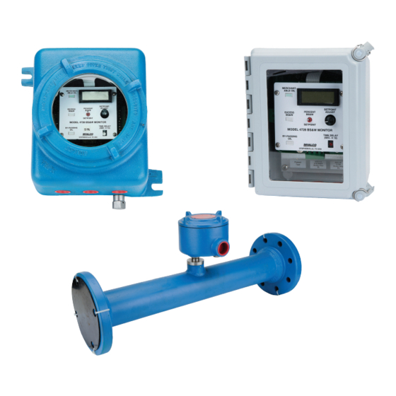
- Page 1 MANUAL Water Cut Monitor 4528 Detector, CX-645 Probe, CSA Approved 4728 Monitor Installation / Operation Manual Bulletin MNIN003 Issue/Rev 0.0 (5/19)
- Page 2 24/7 Technical Support/Schedule a Technician: 1-844-798-3819 System Installation Supervision, Start-Up, and Commissioning Services Available Customer Support Contact Information: Customer Service TechnipFMC FMC Technologies Measurement Solutions Inc. 1602 Wagner Avenue Erie, Pennsylvania 16510 USA P: +1 814 898-5000 F: +1 814 899-8927 measurement.solutions@TechnipFMC.com...
-
Page 3: Table Of Contents
Installation Hints ..................................17 Troubleshooting ..................................18 Recommended Spare Parts ............................... 18 4728 with Explosion-proof Enclosure – Dimensional Drawing ....................19 4728 with Weather-proof Enclosure – Dimensional Drawing ..................... 20 CX-645 Probe – Dimensional Drawing ............................21 Issue/Rev. 0.0 (5/19) ║ MNIN003 • Page 3... - Page 4 Page intentionally left blank. Page 4 • MNIN003 ║ Issue/Rev. 0.0 (5/19)
-
Page 5: Introduction
Installation / Operation Manual Introduction The 4728 S & W Monitor used in conjunction with a Model 4528 Detector Card and Model CX-645 Probe, provides continuous on-line monitoring of percent water in crude oil. The monitoring system measures changes in the product stream capacitance. The di- electric constant (Dk) (a key factor in capacitance measurement) of the product stream changes dramatically as water content varies. -
Page 6: Percent Water Set Point
Model 4728. The 20 mA point is factory preset. The Model 4728 utilizes a loop switch to determine whether the 4-20 mA loop will be self powered or powered by a remote supply. In the internal mode the unit will drive 4-20 mA through a maximum loop resistance of 600 ohms. - Page 7 Failure to have the switch in the proper position may cause component failure and void the unitʼs warranty. The function and operation of all other controls on the 4728 are as described in the manual. Issue/Rev. 0.0 (5/19) ║ MNIN003 • Page 7...
-
Page 8: Model 4528 Detector - Types A, B, And C
Installation / Operation Manual Model 4528 Detector – Types A, B, and C The Model 4528 Detector mounts in the explosion proof conduit on the capacitance probe. It converts water changes in the oil flowing through the probe to an output volt- age that varies with the water. -
Page 9: Wiring Diagram
Installation / Operation Manual plate by using the three screws marked “A” on the drawing. Wiring Diagram Note: Spade Lugs are not used on CSA Approved Model 4728. Note: Typical Interconnecting cable between Detector and Readout. Maximum recommended length is 300 feet. -
Page 10: 4-20 Ma Loop
Warning: Loop Switch MUST be up in external position BEFORE connecting external power on 4728 with bottom terminal strip. Loop Switch MUST be up before connecting external power on CSA Approved Model 4728 with the two sides and bottom terminal strips. - Page 11 Installation / Operation Manual The probe is constructed of two concentric tubes. Wetted and internal surfaces are coated with a fused epoxy powder. The inner tube is insulated from the outer tube by PTFE (polytetrafluoroethylene) spacers and is electrically connected to a terminal within the sensor housing.
-
Page 12: Typical Applications
Indicating Unit used to provide an analog output proportion to water housing. A 3-15 psi pneumatic output signal is provided cut. The 4728 Indicating Unit is not required. directly proportional to the percent water in the process. Percent Water Recording... -
Page 13: Typical Tank Flow Diagram
Installation / Operation Manual Typical Tank Flow Diagram Issue/Rev. 0.0 (5/19) ║ MNIN003 • Page 13... -
Page 14: Detector Calibration - 4528 0-5 Vde Output
Turn on power/system to cause oil to flow through probe. Allow flow to stabilize. Take grindout of water in oil. For calibration purposes the oil should preferably have less than 1% water in it. Apply power to Model 4728 indicator unit. Ignore lights until calibration is complete. A. 4528 Detector 1. -
Page 15: Detector Calibration - 4528-X A With 4-20Ma Module Mounted "Piggy Back" On Detector Card
Installation / Operation Manual Detector Calibration – 4528-X A with 4-20mA Module Mounted "Piggy Back" on Detector Card A. Calibration 4528-X A With 4-20 mA Module Mounted “Piggy Back” on Detector Card 1. Remove Detector aluminum face plate by removing the three 6-32 mounting screws and the bottom screw on P.C. - Page 16 2. The 4-20 mA loop is internally powered from the 4528-A. DO NOT USE an external loop power source. The 4528-5A Detector Card is designed to supply a 4-20 mA signal direct to an external readout device. It is not designed to be used with a Model 4728 Readout Unit. 3. Maximum Loop Resistance is 250 ohms.
-
Page 17: Detector Information - Type B And C
Installation / Operation Manual Detector Information – Type B and C Type “C” Detector with Fail-safe Switch - This switch allows the output from the Detector Chassis to be tailored to the requirements of the customer. The Fail-safe Switch is located on the upper right side of the printed circuit board under the cover plate. -
Page 18: Troubleshooting
Heavy electrical static in air being picked up by while water cut is steady. 4-20 mA wiring. Use shielded twisted pair wire for 4-20 mA signal from 4728 Unit to external readout. Ground shield at 4728 Unit only. DO NOT ground shield at both ends of wire. -
Page 19: 4728 With Explosion-Proof Enclosure - Dimensional Drawing
Installation / Operation Manual 4728 with Explosion-proof Enclosure – Dimensional Drawing Issue/Rev. 0.0 (5/19) ║ MNIN003 • Page 19... -
Page 20: 4728 With Weather-Proof Enclosure - Dimensional Drawing
Installation / Operation Manual 4728 with Weather-proof Enclosure - Dimensional Drawing Page 20 • MNIN003 ║ Issue/Rev. 0.0 (5/19) -
Page 21: Cx-645 Probe - Dimensional Drawing
Installation / Operation Manual CX-645 Probe – Dimensional Drawing Issue/Rev. 0.0 (5/19) ║ MNIN003 • Page 21... - Page 22 FMC Technologies Measurement Solutions Inc. Germany Operation 13460 Lockwood Road Smith Meter GmbH Building S01 Regentstrasse 1 TechnipFMC.com Houston, Texas 77044 USA 25474 Ellerbek, Germany P:+1 281.591.4000 P:+49 4101 304.0 MNIN003 Issue/Rev. 0.0 (5/19) © 2019 TechnipFMC plc. All rights reserved.
Need help?
Do you have a question about the 4728 and is the answer not in the manual?
Questions and answers