
Subscribe to Our Youtube Channel
Related Manuals for TechnipFMC Sening MultiLevel


Summary of Contents for TechnipFMC Sening MultiLevel
- Page 1 MANUAL Level Gauging System MultiLevel Instruction Manual Bulletin MNF18001EN / DOK-479-E Issue/Rev 1.4 (9/18)
- Page 2 - New company branding Important All information and technical specifications in this documentation have been carefully checked and compiled by the author. However, we cannot completely exclude the possibility of errors. TechnipFMC is always grateful to be informed of any errors. Measurement Solutions...
-
Page 3: Table Of Contents
MultiLevel Instruction Manual Table of Contents 1 – General ................5 7.1.5. MultiLevel functionality with NoMix ........ 46 1.1. Orientation aids for the manual ......... 5 7.1.6. Stand-alone mode ............47 7.2. Wet leg sensor interface – NM2WET-E ......47 7.3. - Page 4 MultiLevel Instruction Manual Table of Contents 10.3.1. Input dialogue ............136 9.7.1.4.3.1. Valve Control – 31431 .......... 95 10.3.2. Parameters ..............137 9.7.1.4.3.2. Loadplan Query – 31432 ........95 10.3.1. Changing forms after sealing ........137 9.7.1.4.3.3. Loading Measurement – 31433 ......95 9.7.1.4.4.
-
Page 5: General
MultiLevel Instruction Manual General 1 – General 1.1. Orientation aids for the manual We have provided some orientation aids so that you can easily find the necessary information in this manual. The information in this manual ranges from imperative safety procedures and standardized guidelines through to concrete handling procedures and advice. - Page 6 Page intentionally left blank. Page 6 • MNF18001EN / DOK-479-E ║ Issue/Rev. 1.4 (9/18)
-
Page 7: Installation
MultiLevel Instruction Manual Installation 2 – Installation The installation of the system to a road tanker may only be carried out by a qualified company. This qualified company carries out and tests the whole system according to the testing criteria set out in the operation and installation instructions. The correct fitting of the system is to be certified. -
Page 8: To Ensure Trouble-Free Operation
MultiLevel Instruction Manual Installation 2.1.3. To ensure trouble-free operation When carrying out welding work on the vehicle, please disconnect current supply to all electronic components. The lead entries must always be mounted at the side or underneath in order to prevent the ingress of water into the housing. - Page 9 MultiLevel Instruction Manual Installation If it can be proven that guidelines were not observed, or installation was carried out by unqualified personnel (violation of applicable regulations) we assume no liability for the malfunctions experienced and any further claims that may arise thereof.
-
Page 10: Maintenance
MultiLevel Instruction Manual Installation 2.3. Maintenance The devices must not be modified mechanically or electronically in any way. During cleaning with a steam cleaner or with pressurized water, the devices should be protected from the water jet. Never aim the steam jet directly onto the devices! We cannot accept responsibility for any damage caused by moisture in the equipment as a result of improper cleaning procedures. -
Page 11: Operating Elements
MultiLevel Instruction Manual Installation 2.4.3. Operating elements CAUTION: Do not open the housing cover when the unit is connected to the voltage supply! Work must only be carried out on the Ex-e terminals when the unit is voltage free. National regulations must be satisfied when operating this unit. When performing operational checks, observe the guidelines laid out in IEC / EN 60 079-17. -
Page 12: Proper Intended Use
MultiLevel Instruction Manual Installation 2.4.5. Proper intended use The measuring systems are to be used exclusively for delivery of low-viscosity mineral oils on tank trucks. The corresponding applicable safety regulations (e.g. Ex protection) must be complied with. Any form of use which exceeds the scope described above is deemed to be improper use;... -
Page 13: Quick Start
MultiLevel Instruction Manual Quick Start 3 – Quick Start The following status screen is displayed when the MultiLevel system is switched on: Start screen Operation: To start a discharge process, press <F3>. If necessary, the compartment monitoring screen will be displayed and you will be instructed to connect the hoses. - Page 14 MultiLevel Instruction Manual Quick Start Discharge screen – pre-selection Operation: The volume pre-selection query can now be used to modify the default volume by entering a new value using the number keys <1>...<0>. The new value must be greater than the minimum discharge volume.
- Page 15 MultiLevel Instruction Manual Quick Start Conditions for metered and calibrated DISCHARGE processes. The following conditions must be fulfilled for a metered discharge process to take place: • The fuel level is within the range of the dip table and the slope table. •...
- Page 16 MultiLevel Instruction Manual Quick Start Discharge screen – Pause Operation: This example shows the discharge of compartment <1>. You can stop the discharge at any time by pressing the compartment number (the <1> key in the example shown). This closes both the foot valve and the line valve of the compartment in question and MultiLevel switches to a pause status.
- Page 17 MultiLevel Instruction Manual Quick Start If the wet-leg sensor shows as 'wet' due to the medium passing through from the compartment, the current discharge process can be started at any time by connecting the discharge hose and pressing the compartment number as long as no delivery note has been printed! The process described is then repeated.
-
Page 18: Operating Error
MultiLevel Instruction Manual Quick Start 3.1. Operating error Unable to leave operating mode. • If you are in the NoMix "Menu", for example, and press "Discharge" or "Load- ing" for MultiLevel, and are then unable to navigate to or leave the mode in question, then please check the NoMix device to establish whether it is in the same mode as the MultiLevel device. -
Page 19: Remote Access To Nomix
MultiLevel Instruction Manual Remote Access to NoMix 4 – Remote Access to NoMix The basic screen is normally displayed after switching on and is in the basic state: NoMix can also be operated without its own display. MultiLevel then displays the NoMix information. -
Page 20: Delivery
MultiLevel Instruction Manual Remote Access to NoMix Loading Screen (2) Operation: Press again the <F2> button to change in the NoMix display. Loading NoMix Screen Operation: To return to the MultiLevel display: In NoMix by a short pressing the ... - Page 21 MultiLevel Instruction Manual Remote Access to NoMix Delivery Screen Operation: All operating steps and displays are performed on the MultiLevel, a display of the NoMix screen is only required in a few cases, eg for entering a bypass. For this purpose initially pressing the ...
- Page 22 Page intentionally left blank. Page 22 • MNF18001EN / DOK-479-E ║ Issue/Rev. 1.4 (9/18)
-
Page 23: Description Of The Level Gauging System
MultiLevel Instruction Manual Description of the Level Gauging System 5 – Description of the Level Gauging System 5.1. Electrical components Figure 1: Electrical components 5.2. Mechanical components For a correct temperature-volume conversion for the delivery and for the filling, the temperature sensor (9) must be installed near the bottom valve (6) to ensure a reliable incident flow in both modes! Pos. -
Page 24: Functional Description
The choice of materials, particularly with regard to resistance to media and weldability in combination with other tank materials, is the responsibility of the tank truck manufacturer. TechnipFMC does not offer any guarantee of the weldability of the parts in combination with the tank materials. - Page 25 MultiLevel Instruction Manual Description of the Level Gauging System The filling height of each compartment is assigned a filling volume via a compartment-specific gauge table, whereby intermediate values within the table are interpolated linearly (see figure xxx). The delivery quantity corresponds to the difference between the fill volume before and after the delivery.
- Page 26 MultiLevel Instruction Manual Description of the Level Gauging System Figure 6: Typical inclination correction curves The calibration limit of the absolute inclination correction values is determined by the accuracy of the angle sensor. If the correction values become too large in relation to the size of the compartment, the error due to the angle sensor exceeds the calibration limits and the compartment can no longer be calibrated.
-
Page 27: Condition For The Calibration Capability
Due to the inclination correction in particular, certain geometry requirements arise that must be adhered to. If necessary, TechnipFMC will be pleased to assist you in the planning phase. • It is essential to comply with the accuracy requirement when installing the level sensors. - Page 28 MultiLevel Instruction Manual Description of the Level Gauging System Figure 8: Operating Principle • A microcontroller measures the transit time and, from that and the wire length, calculates the float position. Figure 9: Level sensor Page 28 • MNF18001EN / DOK-479-E ║ Issue/Rev. 1.4 (9/18)
-
Page 29: Transmission Of The Level Sensor Data
MultiLevel Instruction Manual Description of the Level Gauging System 5.5.1. Transmission of the level sensor data Special M12 plug-in connector by Hirschmann. Figure 10: Level sensor plug-in connector The data is transferred digitally to the level sensor interface, whereby the level sensor can only send data. - Page 30 MultiLevel Instruction Manual Description of the Level Gauging System Figure 11: Tank shapes Calibration unit The calibration of the tank compartments is carried out with the aid of the calibration system. Following calibration, the calibration data is transmitted to the tank truck by means of a chip card.
-
Page 31: Diagram Of A Typical Volumetric Measurement Curve (Created From The Gauge Table)
MultiLevel Instruction Manual Description of the Level Gauging System 5.6.2. Diagram of a typical volumetric measurement curve (created from the gauge table) Figure 13: Graph of a typical volumetric measurement curve The graph shown above is stored as a table in the MultiLevel. Each height is assigned a filling volume. -
Page 32: Graph Of A Typical Inclination Correction Curve
MultiLevel Instruction Manual Description of the Level Gauging System 5.7.1. Graph of a typical inclination correction curve Figure 15: Typical inclination correction curves The graph shown above is stored as a table in the MultiLevel. Each height is assigned an inclination correction volume. Intermediate values are interpolated linearly. - Page 33 MultiLevel Instruction Manual Description of the Level Gauging System • Calculation specification for the angle correction: Raw sensor data + Sensor correction + Installation correction = Vehicle Inclination (see also pre-testing models DOK-476 inclination sensor) • Procedure for inputting the angle corrections: Entry of the correction values from the pre-acceptance test certificate Alignment of the vehicle to 0°...
-
Page 34: Height Definition Of The Sensor Head
MultiLevel Instruction Manual Description of the Level Gauging System Y – Correction in the transverse direction: X – Correction in the longitudinal direction: The correction values are determined experimentally and checked by the W&M official in the case of an official calibration acceptance. 5.8. - Page 35 MultiLevel Instruction Manual Description of the Level Gauging System Figure 18: Height definitions (drawing: 51.251916) Issue/Rev. 1.4 (9/18) ║ MNF18001EN / DOK-479-E • Page 35...
- Page 36 Page intentionally left blank. Page 36 • MNF18001EN / DOK-479-E ║ Issue/Rev. 1.4 (9/18)
-
Page 37: Inst. Of The Mechanical Level Sensor Comp
MultiLevel Instruction Manual Installation of the mechanical level sensor components 6 – Installation of the mechanical level sensor components 6.1. Packing the level sensors The level sensors are sensitive measuring instruments, which must be transported and handled carefully. The level sensors must be transported in sturdy packaging. -
Page 38: Transporting The Level Sensors
MultiLevel Instruction Manual Installation of the mechanical level sensor components 6.2. Transporting the level sensors Care must be taken in every case before assembly that the level sensors do not bend. On no account may the level sensors be grasped centrally or carried without supporting the sensor head. -
Page 39: Structure Of The Sensor Head
MultiLevel Instruction Manual Installation of the mechanical level sensor components 6.3. Structure of the sensor head Figure 25: Structure of the sensor head (Drawing 71.251579) Flanges of type TW220 DN65 are required for the installation of the level sensors. (Tipping valve flange). The part numbers are shown on the assembly drawings in the appendix. -
Page 40: Mechanics
MultiLevel Instruction Manual Installation of the mechanical level sensor components 6.5. Mechanics 6.5.1. Installation specifications for the sensor head Assembly aperture for inserting the level sensor. (use screwdriver, for example, as an aid.) ATTENTION: Recommended gap protective tube → cover: <5 mm Otherwise danger of the protective tube jumping out of the guide. -
Page 41: Cable Plug Connector
MultiLevel Instruction Manual Installation of the mechanical level sensor components Figure 29: Float ATTENTION: The lettering on the float must always face the sensor head. 6.5.3. Cable Plug Connector The level sensor is equipped with an M12 plug-in connector. Figure 30: Level sensor plug-in connector ATTENTION: We use special cable sockets made by Hirschmann, which have proven to be leak proof. - Page 42 MultiLevel Instruction Manual Installation of the mechanical level sensor components Technology • Measurement accuracy better than ±0.2 mm • Resolution better than 0.1 mm • Measurement evaluation controlled by microcontroller • Temperature-compensated measurement principle • 2-wire connection, digital transmission of measured values •...
-
Page 43: Modules
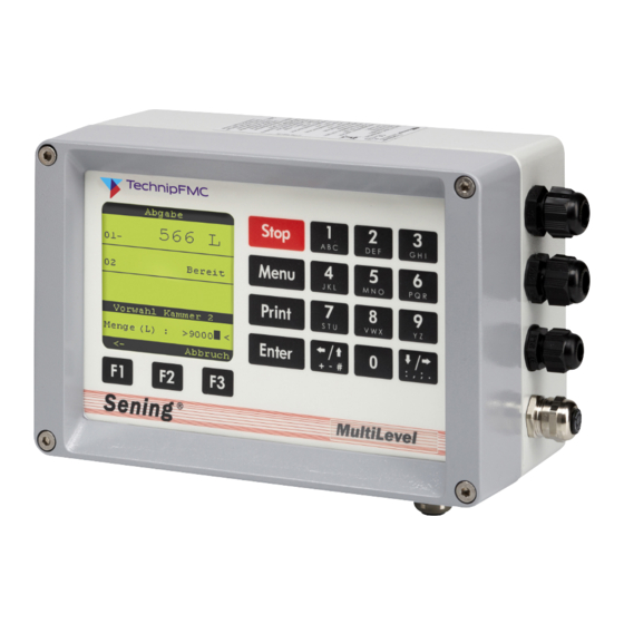
MultiLevel Instruction Manual Modules 7 – Modules 7.1. Main Unit / Display – MLMAINDISP / MLMAINDISP2 Parts no.: MLMAINDISP2 Drawing no.: 61.352025 Wiring diagram no.: 51.351673 Display Function keys Numeric keys Figure 32: Main Unit and Display – MLMAINDSIP2 The main unit/display, part no. MLMAINDISP2 is the central control unit of the MultiLevel system. -
Page 44: Display / Keyboard 2 - Mlmaindisp2
MultiLevel Instruction Manual Modules 7.1.1. Display / keyboard 2 – MLMAINDISP2 The MultiLevel system is operated via the keyboard and the display. Parts no.: MLMAINDISP2 Drawing no.: 61.352025 Connector for Wiring diagram no.: 51.351673 chip card reader Name strip Display CPU board MAIN Unit CPU board SD card PCB with memory card... -
Page 45: Display Interface - Keyboard Functions Definition Of Symbols And Key Functions
MultiLevel Instruction Manual Modules 7.1.3. Display Interface – Keyboard Functions Definition of Symbols and Key Functions Table 1: Key functions Important functions and inputs • Entering the parameters / SETUP (adaptation of the MultiLevel system to different tank truck variants) •... -
Page 46: Important Functions And Settings
MultiLevel Instruction Manual Modules 7.1.4. Important functions and settings • Entering the SETUP (adaptation of the MultiSeal system to different tank trucks variants). • Execution of tests during commissioning and troubleshooting. • Printout of MultiLevel reports. • Printout of: Parameters (Setup), gauge tables, logbook, screenshots. •... -
Page 47: Stand-Alone Mode
MultiLevel Instruction Manual Modules 7.1.6. Stand-alone mode In stand-alone mode, the I/O interface (chapter 7.8 "I/O interface - NM2IO") is connected directly to the MultiLevel for the control of the foot and line valves. As a result of that, all information from the NOMIX system is omitted: •... -
Page 48: Wet Leg Sensor - Ns-2E
MultiLevel Instruction Manual Modules The wet leg sensor interface evaluates the fill level of the tank truck compartments via wet leg sensors (part no. NS-2E) installed in the pipe system of each individual tank truck compartment. The compartment state can either be empty or not empty/filled. Short-circuits and interruptions such as the detachment of the plug-in connectors can be detected. -
Page 49: Temperature Sensor - Mldts-2
MultiLevel Instruction Manual Modules 7.4. Temperature sensor – MLDTS-2 Parts no.: MLDTS-2 Drawing: 51.351978 Wiring diagram: 61.351918 Figure 37: Temperature sensor – MLDTS-2 The temperature sensor MLDTS-2 serves for the temperature measurement in the piping system. It is connected to the level sensor interface - MLIF. All components are installed in a housing and sealed for protection against the influences of the weather. -
Page 50: Chip Card Reader - Ccr
MultiLevel Instruction Manual Modules As a component of the MultiLevel level sensor system, the task of the inclination sensor MLIS on tank trucks is to measure the inclination in the longitudinal and transverse directions. It is connected to the level sensor interface – MLIF. All components are installed in a housing and sealed for protection against the influences of the weather. - Page 51 MultiLevel Instruction Manual Modules The I/O interface (output driver interface) is used for controlling solenoid valves that start or stop the delivery/filling process pneumatically. The I/O interface receives information from the MultiLevel for the control of a solenoid valve. The solenoid valves of the already certified NoMix system are preferably used. Second I/O Interface In some tank truck types such as measuring system, hybrid trucks or trucks with more than 6 compartments and trucks in which the foot valves and in-line...
- Page 52 Page intentionally left blank. Page 52 • MNF18001EN / DOK-479-E ║ Issue/Rev. 1.4 (9/18)
-
Page 53: Commissioning
MultiLevel Instruction Manual Commissioning 8 – Commissioning Before switching the system on for the first time, re-check the wiring for correct connection and firm fit one more time. Insert the fuse, so that power is supplied to the MultiLevel system. ... - Page 54 MultiLevel Instruction Manual Commissioning The following display appears: <Display test>: All ASCII characters are displayed; the test ends automatically. <Own-address>: (CAN bus address) The <F1> and <F2> keys, “plus” and “minus” are then used to set the respective CAN address.
-
Page 55: Menu Structure
MultiLevel Instruction Manual MENU structure 9 – MENU Structure The MENU structure of the MultiLevel system consists of pull up and pull down menus. Submenus are accessible from the main menu and vice versa. Refer also to the short overview of the menu system in chapter 15 "Short overview of menu system". -
Page 56: Temperature-Compensated Measurement During Loading
MultiLevel Instruction Manual MENU structure The same display appears even if the mode is changed to loading in the case of the NoMix 2000 system. By pressing the <F2> key (= more) it is possible to access a further display, where the fill levels of the individual compartments are displayed as percentages in bar charts. -
Page 57: Delivery
MultiLevel Instruction Manual MENU structure 9.2. Delivery Start display delivery In the Help displays (compartment info) you can scroll through individual info-pages (max. 10) using the arrow keys (← / →). Or it can be changed in advance as usual. Delivery is started when the pre-selected quantity is confirmed (<ENTER>... -
Page 58: Print Reports And Tables
MultiLevel Instruction Manual MENU structure For the Help displays (compartment info) you can scroll through the individual info-pages (max. 10) using the arrow keys ← / →. When scrolling through the compartments using <F2> the display of pre-selected quantity appears again after the last compartment. -
Page 59: Print <1> - Setup
MultiLevel Instruction Manual MENU structure Explanation of the submenus Setup: Printout of the parameters Tables: Printout of the gauging tables Logbook: Printout of the event logbook (for example: Event Report, Loading and Delivery Note, Receipt copies etc. Report: Printout of the tour reports 9.3.1. - Page 60 MultiLevel Instruction Manual MENU structure Operation Options MultiLevel ???????? 16.05.11 12:57 -02- ------------------------------------------ ------------------------------------------ 31411 Change LPlan always 3132144 Max. Roll Slope 3.00 314211 Preset Query 3132145 Min. Dlv. Volume 5000 314212 Preset Type Preset to V0 3132146 Max. Volume Change 314213 Auto-Adjust 3132147 Max.
- Page 61 MultiLevel Instruction Manual MENU structure 1B77001B541B2100 32521 10 CPI 1B501B32 MultiLevel ???????? 16.05.11 12:58 -06- 32522 12 CPI 1B4D1B32 ------------------------------------------ 32523 12 CPI 1B671B30 351272 Comp. Temperature 32524 Double Width 1B5701 351273 Comp. Method 32525 Double Height 1B77011B3336 351274 Average Density 836.0 32531 Condensed font 1B671B30...
-
Page 62: Setup
MultiLevel Instruction Manual MENU structure ------------------------------------------ 3662 Driver Name Driver 6 3611 Driver Number 3663 Master Keyword 3612 Driver Name Driver 1 3671 Driver Number 3613 Master Keyword 3672 Driver Name Driver 7 3621 Driver Number 3673 Master Keyword 3622 Driver Name Driver 2 3681 Driver Number 3623 Master Keyword...- Ptb Parameter List -
Page 63: Print <2> - Tables
MultiLevel Instruction Manual MENU structure 9.3.2. PRINT <2> – Tables The Print Tables menu looks like this: Press the <2> button to enter the MultiLevel tables print menu for printing the gauging and slope tables. The appropriate submenu is accessed ... -
Page 64: Gauging Table
MultiLevel Instruction Manual MENU structure 9.3.2.2. Gauging Table Gauging table 393.524 mm 1472.182 L (sample printout!) 402.224 mm 1517.075 L 411.193 mm 1564.275 L 16.05.2011 14:07:38 419.563 mm 1609.181 L Device : MultiLevel 428.164 mm 1656.160 L ------------------------------------------ 436.525 mm 1700.497 L Version : 1.23[1.27]DE... - Page 65 MultiLevel Instruction Manual MENU structure 949.884 mm 4567.786 L 1492.095 mm 7256.981 L 958.290 mm 4613.257 L 1500.970 mm 7295.272 L 966.908 mm 4661.010 L 1509.462 mm 7329.086 L 975.519 mm 4708.500 L 1517.893 mm 7362.944 L 983.863 mm 4754.040 L 1526.316 mm 7396.777 L 992.273 mm...
-
Page 66: Tables <2> - Slope Table List
MultiLevel Instruction Manual MENU structure 9.3.2.3. Tables <2> – Slope Table List Slope table 1610 1610 2531 3673 5043 6654 (sample printout! NOT complete!) 8518 10651 13068 15790 18836 22232 25999 30170 16.05.2011 14:38:04 ---------- No. 31.000 mm --------- Device : MultiLevel 40969 32592... - Page 67 MultiLevel Instruction Manual MENU structure 17782 23843 30628 38006 60019 68712 77646 86815 96206 105801 115605 125669 45884 54194 62881 71893 81204 90800 100611 110728 48489 42270 36534 31254 26429 22041 18091 14561 59192 51957 45197 38829 11438 8711 6370 4406 33079 27747...
-
Page 68: Print <3> - Logbook
MultiLevel Instruction Manual MENU structure 9.3.3. PRINT <3> – Logbook The Print Logbook menu looks like this: Press the <3> button to enter the MultiLevel logbook print menu. The appropriate submenu is accessed by pressing the <numeric keys> (here, for example, <1>... -
Page 69: Logbook <1> - Event Report List
MultiLevel Instruction Manual MENU structure 9.3.3.2. Logbook <1> – Event Report List Event report 11:27:40 50 BottomValve 1: OPEN 11:27:48 51 Dlv. 1 : Lvl1 11:27:52 52 Dlv. 1 : StartDlv (sample printout! NOT complete!) 11:27:57 53 Dlv. 1 : Dlv 11:27:57 54 Line Valve 1: OPEN 09.04.2010 10:15:17 - 16.05.2011 12:45:37... -
Page 70: Logbook <2> - Parameter Report List
MultiLevel Instruction Manual MENU structure 13.04.2010 11:55:19 115 BottomValve 1: OPEN 11:55:24 116 Dlv. 1 : Dlv 14:52:16 134 Power ON 14:52:19 135 Main Mode D 11:55:24 117 Line Valve 1: OPEN 11:55:28 118 Dlv. 1 : Wetleg 14:52:19 136 Delivery 1 finished 11:56:18 119 Wetleg 1 DRY 14:52:30... -
Page 71: Logbook <3> - Comp. Monitor Logbook
MultiLevel Instruction Manual MENU structure 9.3.3.4. Logbook <3> – Compartment Monitor Logbook The Print Compartment Monitor Logbook menu looks like this: The <ID> and <Password> for master authorisation are required in order to print the comp. monitor logbook. See also chapter 9.3.3 "PRINT <3>... -
Page 72: Logbook <5> - Updates
MultiLevel Instruction Manual MENU structure 9.3.3.5.1. Logbook <4> – Meter Results Logbook List (Loading / Delivery Note) Loading note (sample printout!) (sample printout!) (Copy) (Copy) Start date 09.04.2010 Start date 27.04.2011 Tanknumber - ? - Tanknumber - ? - Receipt no. Receipt no. -
Page 73: Print <4> - Report
MultiLevel Instruction Manual MENU structure 9.3.3.6.1. Logbook <5> – Update Report List Update report (Sample printout!) 17.10.2010 14:48:45 - 07.11.2010 19:38:22 Device : MultiLevel ------------------------------------------ Version : 1.23[1.27]DE Sealcounte : 000003 Serial no. : 18AB1234 Comp. no. : 1234ABCD ------------------------------------------ Seal broken! ------------------------------------------ Remaining attempts... -
Page 74: Report <1/2> - Tour Report List - Example 1
MultiLevel Instruction Manual MENU structure 9.3.4.1. Report <1/2> – Tour report List – Example 1 Tour report (sample printout!) Example 1: Total block for compartments 01.07.2010 13:42:45 - 15.09.2010 12:46:10 Device : MultiLevel ****************************************** Report header: * Version : 1.22[1.26]EN •... -
Page 75: Settings And Changes
MultiLevel Instruction Manual MENU structure 9.3.4.2. Report <1/2> – Tour report List – Example 2 Tour report Example 2: (sample printout!) Total block for products 01.07.2010 13:42:45 - 15.09.2010 12:46:10 Device : MultiLevel ****************************************** Report header: * Version : 1.22[1.26]EN •... -
Page 76: Display Configuration - 1
MultiLevel Instruction Manual MENU structure Explanation of the submenus 1 Display config.: Configuration of the display 2 Loading plan: Display of the loading plan 3 Parameter list: Input of the setup parameters 4 Service: Call-up of diagnosis functions 5 Remote access: Remote access functions 6 Data transmission: Data transmissions functions... -
Page 77: Display Of The Loading Plan - 2
MultiLevel Instruction Manual MENU structure 9.6. Display of the loading plan – 2 Loading plan display with NoMix If MultiLevel is operated together with NoMix, only the fill levels and the product can be read off here in the loading plan display. -
Page 78: Parameter List - 3
MultiLevel Instruction Manual MENU structure 9.7. Parameter list – 3 During commissioning of the MultiLevel system, the “tank truck supplier” has to adapt the system to the respective tank truck type. This is done here in the ‘Parameter list’ submenu, which in turn possesses further submenus. -
Page 79: Device Setting - 31
MultiLevel Instruction Manual MENU structure The correct adjustment of the SETUP is to be certified by the specialist company. The parameter list must be printed out in addition to being recorded on an appropriate form. Furthermore, the parameter list should also be stored on a chip card for archiving. In order to do this, the chip card reader / writer (part number: CCR) must be connected at least when entering the parameters. -
Page 80: Global Can Bus - 312
MultiLevel Instruction Manual MENU structure *3114 – No. Wetleg interface (wet-leg detector interface) Setting showing how many wet-leg detector interfaces are installed. At present, the software only supports one wet-leg detector interface. *3115 – No. I/O interface (wet-leg detector interface) Setting to show how many I/O interfaces are installed. -
Page 81: Chambers - 313
MultiLevel Instruction Manual MENU structure 9.7.1.3. Chambers – 313 Compartment-specific parameters are set here: Explanation of the submenus 1 Number of compartments 2 Compartments 1-10 3 Compartments 11-20 4 Compartments 21-30 5 Compartment monitoring 3131 – Number of compartments Here the number of chambers is set. At the present time, the maximum number is limited to 24 compartments. -
Page 82: Compartment 1 Sensors - 313211
MultiLevel Instruction Manual MENU structure 9.7.1.3.1.1.1. Compartment 1 Sensors – 313211 The settings for the various sensors are made here: The following parameters already contain the number of the related compartment as a preliminary setting. Alternatively, the values can be altered if so desired 3132111 –... -
Page 83: Compartments 1 Data - 313213
The height of the ice protection (= ice protection offset ) is set here. The standard value is 25.0 mm and may only be changed in exceptional cases on consultation with TechnipFMC. → value in 1/1000 mm. 3132123 – Inclination tab. offset A possible inclination table offset can be set here. - Page 84 → value in 1/1000 mm → specified: 40000 μm = 40mm (Deviations permitted only in special cases and only on consultation with TechnipFMC) 3132135 – Float MAX Max. fill level that should be reached when calibrating the compartment. This value serves to avoid overfilling during calibration by automatically switching off the pump when the value is exceeded.
- Page 85 MultiLevel Instruction Manual MENU structure 3132136 – Correction A fixed correction factor (= K-factor) can be set here, if a linear deviation between the display on the MultiLevel and bell prover is determined during measurements in the bell prover. K affects only the volume in accordance with the level sensor table, not the correction volume of the inclination table and not the residual volume! = volume in the bell prover target...
- Page 86 MultiLevel Instruction Manual MENU structure 3132139 – Max. Switch Point • During filling, overfilling individual compartments should be avoided. • The Loading pre-switching is to operate separately for each compartment. Tripping the Loading pre-switching for a particular (overfilled) compartment has no effect on current filling operations of other compartments.
-
Page 87: Compartments 1 - Calibration Limits - 313214
MultiLevel Instruction Manual MENU structure Display when switched off by Loading pre-switching (page 1) Compartment 1 - empty - Foot valve closed Compartment 2 - Filling stopped due to overfilling - Gauge moving - Foot valve closed Compartment 3 - Filled - Foot valve closed Display when switched off by Loading pre-switching (page 2) Compartment 1... - Page 88 Rough estimations have shown that relatively small residual volumes remain in the compartments, even if the vehicle deviates by 1° to 1.5° from a favorable alignment. TechnipFMC therefore recommends setting the residual volume de- livery to 1° to 1.5° from the ideal drain direction in order to avoid problems with the delivery.
- Page 89 MultiLevel Instruction Manual MENU structure 3132142 – Max. Pitch Setting for the maximum pitch. If this value is exceeded, the delivery is uncalibrated when the wet leg sensor runs dry. → Example: +3° (Vehicle higher at the front ==> setting is normally suitable for a front compart- ment!) Figure 46: Tank truck inclined positively in a longitudinal direction by +3°...
- Page 90 MultiLevel Instruction Manual MENU structure 3132146 – Max. Diff. V15 • Max. difference V15 can be set separately for each compartment. • Parameter is an absolute amount: positive or negative deviation • 0 liter = OFF (factory setting) → values in litres Comparison between quantity loaded and delivered Comparison of V15 –...
-
Page 91: Compartments 1 - Volume Preset - 313215
MultiLevel Instruction Manual MENU structure 9.7.1.3.1.1.5. Compartments 1 – Volume Preset – 313215 3132151 – Correction Value After the delivery, the correction value for the volume preset is automatically adjusted. This correction value is necessary because, after the command is given to close the valves, a certain amount of time passes before the flow is actually stopped. -
Page 92: Operating Options - 314
MultiLevel Instruction Manual MENU structure 9.7.1.4. Operating Options – 314 Explanation of the submenus 1 General 2 Delivery 3 Loading 7 Help screens 9.7.1.4.1. General – 3141 Select change of loading plan with <1>. 9.7.1.4.1.1. Change Loading Plan – 31411 The <ID>... -
Page 93: Delivery - 3142
MultiLevel Instruction Manual MENU structure In the case of operation with NOMIX, the loading plan can only be viewed. Changes to the loading plan are not possible here. In the case of operation without NOMIX, the loading plan can/must be edited by the driver. -
Page 94: Preset Type - 314212
MultiLevel Instruction Manual MENU structure 9.7.1.4.2.1.2. Preset Type – 314212 Possible settings: "Preset to V0" / "Preset to VT" In the case of ‘Preset to V0’ (factory setting), the volume is preset to the compensated volume (V0). In the case of ‘Preset to VT’, the volume is preset to the uncompensated volume (VT). -
Page 95: Valve Control - 31431
MultiLevel Instruction Manual MENU structure 9.7.1.4.3.1. Valve Control – 31431 Possible settings: "automatic" / "manual" This parameter is effective only if the MultiLevel is operated without NOMIX, i.e. the MultiLevel is equipped with its own I/O interface and controls the foot and line valves itself. -
Page 96: Help Screens - 3147
MultiLevel Instruction Manual MENU structure 9.7.1.4.4. Help Screens – 3147 The information which is to be displayed in the ‘Compartment info’ in the lower third of the display during the delivery is set here in accordance with the numeric key shown below. The help display settings are accessed with <7>. - Page 97 MultiLevel Instruction Manual MENU structure Param. Factory Meaning Setting 3.1.4.7.4.2 Page 4 / line 2: Delivered volume VT in liters 3.1.4.7.4.3 Page 4 / line 3: Delivered volume V15 in liters 3.1.4.7.5.1 Page 5 / line 1: CTL 3.1.4.7.5.2 Page 5 / line 2: API table for the product 3.1.4.7.5.3 Page 5 / line 3: Product density in kg/m³...
-
Page 98: Calibration Restrictions - 315
MultiLevel Instruction Manual MENU structure Description Example >123456789012345678901< Average product temperature [° Kelvin] >Ave. temp. +74,1 °K< Current flow rate <Flow rate 1234 l/min< Average flow rate <Ave. flow 1234 l/min< Mass >Mass 123456 Kg< Average density >Density 123,45 < Compensation YES/NO Reference temperature [°... - Page 99 MultiLevel Instruction Manual MENU structure *31541 – Min. Pitch Slope The minimum pitch permitted in terms of calibration is set here. → This value is preset in the factory to -5.00°. *31542 - Max. Pitch Slope The maximum pitch permitted in terms of calibration is set here. →...
-
Page 100: Printing - 3155
MultiLevel Instruction Manual MENU structure *31545 – Sens. Correction Pitch Each inclination sensor is pre-checked for accuracy and reproducibility in the works by the Office of Weights and Measures. Since the actual inclination sensor chip in the housing can be never installed exactly in the 0-position, the correction value in the longitudinal direction is recorded and entered on the pre-acceptance test certificate. -
Page 101: Printer Settings - 32
MultiLevel Instruction Manual MENU structure 9.7.2. Printer Settings – 32 Printer-specific parameters can be set here: The factory setting should be changed only after consulting F.A. Sening! 321 – Printer selection Various printer types can be set here: DR-295 DR-298 DR-220 ESC/P ESC/P2... -
Page 102: Options - 324
MultiLevel Instruction Manual MENU structure 9.7.2.2. Options – 324 Further optional parameters can be set here: 3241 – Paper Feed Sets whether the automatic paper feed is to be activated. Possible settings: >YES< or >NO< → The factory setting is ‘YES’ 3242 –... -
Page 103: Size - 3252
MultiLevel Instruction Manual MENU structure 32511 – Initialization Character string for initialization. 32512 – Reset Character string for resetting the printer. → Factory setting: 1B40 <ESC> ’@’ 32513 – Delete Attributes Character string to delete all printer attributes. → Factory setting: 1B77001B541B2100 <ESC>... -
Page 104: Attributes - 3253
MultiLevel Instruction Manual MENU structure 9.7.2.3.3. Attributes – 3253 32531 – Condensed Font Character string for changing to condensed font → Factory setting: 1B671B30 ESC ’g’ 15 cpi ESC ’0’ 1/8 inch line spacing 32532 – Bold Font Character string for changing to bold font →... -
Page 105: Wetleg-If - 334
MultiLevel Instruction Manual MENU structure 9.7.3.1. Wetleg-IF – 334 The parameters for the wet-leg detector interface can be set here: *3341 – Activation time Time delay between wet-leg detector report from Empty to Full and the time at which this change is evaluated. →... -
Page 106: Page Layout - 341
MultiLevel Instruction Manual MENU structure 9.7.4.1. Page Layout – 341 The parameters for the 10 available page layouts are set here: The parameters for the first layout are described below. They begin with selection no: 3411xx These parameters must also be set for further layouts if necessary. - Page 107 MultiLevel Instruction Manual MENU structure Receipt Layout (sample printout) Form layout Form layout 13.02.2008 13:15:08 Devic : MultiLevel ****************************************** * Version : ?.??[?.??]DE * Seal counter : 000001 * Serial no. : ???????? * Meter name : - ? - ****************************************** * Seal OK! ******************************************...
-
Page 108: Product Definition - 35
MultiLevel Instruction Manual MENU structure 9.7.5. Product Definition – 35 Product-specific parameters can be set here. → Density value in kg/m³ → Float correction value in μm = 1/000mm The factory setting should be changed only after consulting F.A. Sening! The same applies to extension by a new product. -
Page 109: Product Names - 35111
MultiLevel Instruction Manual MENU structure 9.7.5.1.2. Product Names – 35111 Enter the product name with <1> and the abbreviation with <2>. Table of all used abbreviations: No. Name Abbr. Comp. Density Float Factor Factor Factor Min. Max. code [kg/m corr. -
Page 110: Product 2 - 3512
MultiLevel Instruction Manual MENU structure 9.7.5.1.4. Product 2 – 3512 *35121 – Product name Diesel *35122 – Product type Liquid product *35123 – PTB code *351271 – Compensation *351272 – Comp. temperature *351273 – API table *351274 – Average density 833,0 *351275 –... -
Page 111: Product 6 - 3515
MultiLevel Instruction Manual MENU structure *351474 – Average density 743,0 *351175 – Factor 1 1,27E-3 *351176 – Factor 2 *351177 – Factor 3 *351178 – Min. temp. *351179 – Max. temp. *35149 – Float correction 1750 9.7.5.1.7. Product 6 – 3515 *35161 –... -
Page 112: Product 8 - 3517
MultiLevel Instruction Manual MENU structure 9.7.5.1.9. Product 8 – 3517 *35181 – Product name Jet Fuel *35182 – Product type Liquid product *35183 – PTB code *351871 – Compensation *351872 – Comp. temperature *351873 – API table *351874 – Average density 801,0 *351175 –... -
Page 113: Temp. Compensation - 35117
MultiLevel Instruction Manual MENU structure *353074 – Average density 1000,0 *351175 – Factor 1 *351176 – Factor 2 *351177 – Factor 3 *351178 – Min. temp. *351179 – Max. temp. *35309 – Float correction 9.7.5.1.12. Temp. Compensation – 35117 Select the Temp. Compensation ... -
Page 114: Compensation Method - 35Xx73
MultiLevel Instruction Manual MENU structure 9.7.5.1.13. Compensation method – 35xx73 Select with parameter 35xx73. • Possible selections: – --- no temperature compensation – 54A temperature compensation according to API table 54A – 54B temperature compensation according to API table 54B –... -
Page 115: Service - 4
MultiLevel Instruction Manual MENU structure 9.8. Service – 4 Service main menu screen The Service submenu is accessed from the main menu by pressing <4>. It is then possible to branch off from the ‘Service’ submenu to further submenus. Explanation of the submenus 1 Soft Seal: 2 Calibration:... - Page 116 MultiLevel Instruction Manual MENU structure After switching the seal switch to ‘ON’, confirm this by pressing <F1> = OK. The seal is now broken and you can also change calibration-relevant parameters after entering the various IDs. Set seal screen 414 – Set seal The seal must be set again once all necessary parameters have been changed.
-
Page 117: Calibration - 42
MultiLevel Instruction Manual MENU structure Switching between upper and lower case letters is accomplished with the <F2> key. Press the <F3> key = → to go to the next character, or the <F1> key = ← to go back to the previous letter. This display is exited with the <ENTER>... -
Page 118: Level Sensor Calibration Screen
MultiLevel Instruction Manual MENU structure 9.8.2.1.1. Level sensor calibration screen The offset values for the level sensor are displayed here. These values must be entered into the system first, before the calibration is started. 4211 – Level probes Entry of compartment-specific ... -
Page 119: Inclination Sensor Calibration Screen
MultiLevel Instruction Manual MENU structure ATTENTION: The ‘zeroing’ function may be only executed if the compartment is empty and the float is resting on the ice protection!! 9.8.2.1.2. Inclination sensor calibration screen The sensor correction values and the installation correction values for the incli- nation sensor are displayed here. -
Page 120: Diagnostics - 43
MultiLevel Instruction Manual MENU structure 9.8.3. Diagnostics – 43 All devices connected to the local (internal) CAN bus can be tested in the "Diagnostics Menu". Select the local CAN bus, then the relevant interface for this purpose. 9.8.3.1. Diagnostics, Local CAN bus, Operation (Terminal) 1 – 4311 The software and hardware versions of the operating device (oper.dev.) are displayed in this Diagnostics Menu. -
Page 121: Diagnostics, Local Can Bus, Wetleg-If - 4314
MultiLevel Instruction Manual MENU structure 9.8.3.3. Diagnostics, Local CAN bus, Wetleg-IF – 4314 The software and hardware versions of the wet-leg detector interface are displayed in this Diagnostics Menu. Furthermore, the wet-leg detectors and the two intrinsically safe inputs can be tested. Diagnostics screen 1 for Wetleg-IF Run the wet-leg detector test on all ... -
Page 122: Initialization - 44
MultiLevel Instruction Manual MENU structure Previous behavior: • The foot valves of filled compartments cannot be opened New behavior: • With a sealed device, the behavior is as before. • If the device is not sealed and the DIP switch 8 = ON: Foot valves can always be switched. 9.8.4. - Page 123 MultiLevel Instruction Manual MENU structure Read parameters screen 451 – Read param. Insert a chip card into the chip card reader. Press <F1> in order to read the parameters at master level, i.e. only parameters without calibration protection. This action can be also carried out when the seal is set.
-
Page 124: Software-Update - 46
MultiLevel Instruction Manual MENU structure 457 – Read Layouts The print layouts created previously and stored on the chip card can be read into the MultiLevel’s memory here. The procedure is identical to ‘451 - Read param.’ 458 – Write Layouts The print layouts stored in the MultiLevel are written to the chip card here. -
Page 125: Totalizer - 7
MultiLevel Instruction Manual MENU structure or abort the entry with ‘Stop’ and return to the Logbooks menu. Event logbook screen Delivery logbook screen The events from the specified reporting period can be displayed step-by-step using the <F1> key = PREVIOUS or the <F3> key = NEXT. 9.9. - Page 126 MultiLevel Instruction Manual MENU structure Totalizer screen (page 2) By pressing key <F2> all daily totalizers are reset. Page 126 • MNF18001EN / DOK-479-E ║ Issue/Rev. 1.4 (9/18)
-
Page 127: Form Layout
MultiLevel Instruction Manual Form Layout 10 – Form Layout 10.1. Form Description See also, menus: Additional and more detailed information about menu control can be found on the one hand in chapter chapter 9.7.4 "Form decription - 34" and for the user interface in chapter chapter 10.3 "User interface (operation)". -
Page 128: Identifier - Id For Type Of Receipt Element
MultiLevel Instruction Manual Form Layout 10.2.1. Identifier – ID for type of receipt element The type of receipt element specifies what is printed. The currently available receipt elements are listed and described in the following tables. 10.2.1.1. General receipt elements Page 128 •... - Page 129 MultiLevel Instruction Manual Form Layout Table 4: Form receipt element types (general) • Fields with a dark gray background are not yet available in the current version, since the associated functions have not yet been implemented. Issue/Rev. 1.4 (9/18) ║ MNF18001EN / DOK-479-E • Page 129...
-
Page 130: Compartment Or Product-Related Detail Blocks
MultiLevel Instruction Manual Form Layout 10.2.1.2. Compartment or product-related detail blocks Table 5: Form receipt element types (compartment-related details) 10.2.1.3. Delivery details Page 130 • MNF18001EN / DOK-479-E ║ Issue/Rev. 1.4 (9/18) - Page 131 MultiLevel Instruction Manual Form Layout Issue/Rev. 1.4 (9/18) ║ MNF18001EN / DOK-479-E • Page 131...
- Page 132 MultiLevel Instruction Manual Form Layout Table 6: Form receipt element types (delivery details) • Receipt elements marked with * are calibration-relevant. When saving the layout and before each delivery, a check is performed as to whether the form contains the necessary receipt elements (see ‘Minimum Layout’...
-
Page 133: Y, X - Positions Of The Receipt Elements
MultiLevel Instruction Manual Form Layout 10.2.2. Y, X – Positions of the receipt elements By means of line and column data it can be specified where each receipt element is printed. Here it must be noted that the specified positions for the individual receipt elements relate to the origin of the form (2) or to that of a sub-layout (3). -
Page 134: Attribute - Appearance Properties
MultiLevel Instruction Manual Form Layout 10.2.3. Attribute – Appearance properties A series of print attributes is available to the user for the individual design of the receipt or the individual receipt elements. The selection of the available print attributes is limited by the options offered by the printer used. A character string represents the attributes used (max. -
Page 135: Format - Multi-Purpose Field, Formatting Instructions
MultiLevel Instruction Manual Form Layout The following abbreviations are defined: Table 8: Print options Example: • 'DC' The receipt element with these options is printed only on delivery note copies. • 'v' A text with this option appears only if the electronic seal has been broken (not sealed). •... -
Page 136: User Interface (Operation)
MultiLevel Instruction Manual Form Layout 10.3. User interface (operation) 10.3.1. Input dialogue The input dialogue for a form is intended to put the user in a position to sift through the list of receipt elements that describe a form and to change or delete receipt elements or to add new ones. -
Page 137: Parameters
MultiLevel Instruction Manual Form Layout 10.3.2. Parameters The following parameters are relevant for the control of the delivery receipt: Table 9: Parameters for the control of the delivery receipt 10.3.1. Changing forms after sealing After sealing the MultiLevel, the calibration-relevant parts of the form description are secured against manipulation. - Page 138 Page intentionally left blank. Page 138 • MNF18001EN / DOK-479-E ║ Issue/Rev. 1.4 (9/18)
-
Page 139: Info And Error Messages
MultiLevel Instruction Manual Info and Errors Messages 11 – Info and Error Messages Fault finding and corrective action must be carried out by a service workshop. The warnings on the housings, and generally EN 60079 and VDE 0165 must be followed. -
Page 140: Messages
MultiLevel Instruction Manual Info and Errors Messages Table 10: Overview of system error messages 11.2. Messages 11.2.1. Information Page 140 • MNF18001EN / DOK-479-E ║ Issue/Rev. 1.4 (9/18) - Page 141 MultiLevel Instruction Manual Info and Errors Messages Issue/Rev. 1.4 (9/18) ║ MNF18001EN / DOK-479-E • Page 141...
-
Page 142: Errors
MultiLevel Instruction Manual Info and Errors Messages Table 11: Overview of the messages from the category ‘Information’ 11.2.2. Errors Page 142 • MNF18001EN / DOK-479-E ║ Issue/Rev. 1.4 (9/18) - Page 143 MultiLevel Instruction Manual Info and Errors Messages Issue/Rev. 1.4 (9/18) ║ MNF18001EN / DOK-479-E • Page 143...
- Page 144 MultiLevel Instruction Manual Info and Errors Messages Page 144 • MNF18001EN / DOK-479-E ║ Issue/Rev. 1.4 (9/18)
- Page 145 MultiLevel Instruction Manual Info and Errors Messages Issue/Rev. 1.4 (9/18) ║ MNF18001EN / DOK-479-E • Page 145...
-
Page 146: Seal Breakage
MultiLevel Instruction Manual Info and Errors Messages Table 12: Overview of the messages from the category ‘Errors’ 11.2.3. Seal Breakage Table 13: Overview of the messages from the category ‘Seal breakage’ Page 146 • MNF18001EN / DOK-479-E ║ Issue/Rev. 1.4 (9/18) -
Page 147: Technical Data
MultiLevel Instruction Manual Technical Data 12 – Technical Data 12.1. System Data Approvals: Certification: PTB-A4.5 (PBTWMS-4-411-06-12) Examined after OIML R80 -1 Explosion protection: ATEX II 2 G EEx m ia e IIB T4 Measuring range: 40 to 4.000 mm Measuring accuracy: ±... - Page 148 MultiLevel Instruction Manual Technical Data Sensor circuits: In intrinsically safe level of protection: II 2 G EEx ia IIB with following maximum values: = 16,8 V = 240 mA = 1,0 W Characteristic: linear Max. permissible external inductance = 2,7 mH Max.
-
Page 149: Inclination Sensor Type Llgis
MultiLevel Instruction Manual Technical Data 12.1.3. Inclination sensor type LLGIS Measuring circuit (prefabricated In intrinsically safe level of protection: II 2 G EEx ia cable): IIB/IIA with following maximum values: = 17 V = 260 mA = 1,1 W = 5 nF = 0,25 mH Maximum permissible ambient +60 °C... -
Page 150: Level Sensor S-Ns-2
MultiLevel Instruction Manual Technical Data 12.1.6. Level Sensor S-NS-2... Input circuit: In intrinsically safe level of protection: II 2 G EEx ia Only for connection to a certified intrinsically safe circuit with following maximum values: = 16 V = 52 mA = 208 mW The effective internal capacitance and inductance are negligibly small. -
Page 151: Other Information
MultiLevel Instruction Manual Other Information 13 – Other Information 13.1. Abstract from ElexV (§12) Inspections (1) The operator must arrange for the electrical devices to be inspected for the proper condition of their assembly, installation and operation by a qualified electrician or directed and supervised by a qualified electrician. -
Page 152: Software Replacement
MultiLevel Instruction Manual Other Information 13.3. Software Replacement 13.3.1. Main Unit Prior to each software replacement, the tank truck setup must be recorded or printed, so that during re-commissioning with the new software all vehicle- specific parameters can be reproduced in the setup. The EPROM (contains software) can be found in the main unit on the main CPU board (drawing no. -
Page 153: Memory Partitioning Without Software Separation
MultiLevel Instruction Manual Other Information Example: Calibration-relevant Non-calibration-relevant Height measurement User guidance Inclination measurement Warning messages Detection of wet leg sensors Ext. CAN-Bus (e.g. EMIS) Temperature measurement Languages Volume calculation Printer driver Temperature-volume conversion Volume preset Delivery control Data storage on chip card Parameters Parameters 13.5.2. -
Page 154: Version Name
MultiLevel Instruction Manual Other Information 13.5.4. Version Name 13.5.5. Update Logbook Saves update events within the calibration-relevant area. Currently offers 100 entries. If the logbook is full: no further updates within the calibration-relevant area are saved. Can be reset if the seal is broken. 13.5.6. -
Page 155: Update Procedure
MultiLevel Instruction Manual Other Information 13.5.7. Update Procedure New software is downloaded by means of PC / laptop. The PC is connected to the MultiLevel in place of the printer. The update is transferred to the MultiLevel’s internal SD card first. The update is carried out via an operation on the MultiLevel;... - Page 156 MultiLevel Instruction Manual Other Information If the selected file is not a valid software update: <F1> takes you back to the menu system If the selected file is a valid software update: Entry of the file checksum: The checksum is delivered with the update file and serves for unambiguous identification as well as for ensuring the correct transmission.
- Page 157 MultiLevel Instruction Manual Other Information Finally a last warning is given about the execution of the update, with information about seal breakage if applicable: This is the last opportunity to abort the update procedure by means of <F3>: Pressing <F1> executes the update ...
- Page 158 MultiLevel Instruction Manual Other Information In the last step the system is automatically restarted. No further updates can be performed if the logbook is completely full. In this case the following message appears when menu item 46 is selected: The logbook can only be reset after printing out the update logbook with the seal broken;...
-
Page 159: Multilevel Service Tool
MultiLevel Instruction Manual Other Information 13.6. MultiLevel Service Tool This service tool enables certain functions of the MultiLevel to be accessed via the serial interface. To this end, the MultiLevel’s printer is disconnected and the PC / laptop is connected in its place via a suitable adapter cable (e.g. -
Page 160: Multilevel Service Tool
MultiLevel Instruction Manual Other Information 13.6.1. MultiLevel Service Tool After the program start, no communication with the MultiLevel has been established yet. This is shown by the message ‘Disconnected’ in the status line as well as the symbol on the first button. The MultiLevel should be in the initial state before communication is established: If the MultiLevel is in another mode of... - Page 161 MultiLevel Instruction Manual Other Information The general information is displayed in the window: Version: LRP version: Software version of the program section requiring calibration NRP version: Software version of the program section not requiring calibration Country: Country code of the software: DE: Germany GB: United Kingdom BE: Belgium...
-
Page 162: Multilevel Software Version History/Change Log
MultiLevel Instruction Manual Other Information The operations rename, delete and upload are disabled in the sealed condition for the following file types: *. LOG Logbook *. LGT Gauge table *. ICT Inclination table Double clicking a directory opens it and reads the contents. 13.7. - Page 163 MultiLevel Instruction Manual Other Information Key: Date: Date of approval LRP: Legally relevant part NRP: Legally not relevant part Country Code Date Comment 18.08.08 1.21 [1.21] Temperature-volume conversion for ethanol/petrol mixtures added Erroneous behavior after printing an emergency receipt corrected Calculation of the parameter checksum corrected Error handling for internal level sensor errors changed Warning messages added to the program section ‘Level sensor calibration’...
-
Page 164: Dil Switch Settings For Dr-298-Fdw
MultiLevel Instruction Manual Other Information 13.8. DIL Switch Settings for DR-298-FDW The switches that determine the operating mode of the DR-298 are located in the interior of the unit (see manual). The following factory settings are to be checked on the printer in the event of a ... -
Page 165: Dil Switch Settings Dr-220
MultiLevel Instruction Manual Other Information 13.10. DIL Switch Settings DR-220 The switches for setting the operating mode of the DR-220 are located behind a cover on the underside of the device (see manual). The following factory settings are to be checked on the printer in the event of a ... - Page 166 MultiLevel Instruction Manual Other Information Step 3: - Insert terminal insert into the adapter piece - Attach screw connection and tighten it - Job done! Page 166 • MNF18001EN / DOK-479-E ║ Issue/Rev. 1.4 (9/18)
-
Page 167: Address And Contact Details
MultiLevel Instruction Manual Address and Contact Details 14 – Address and Contact Details Our service department will be happy to assist and can be contacted as follows: TechnipFMC FMC Technologies Measurement Solutions F. A. Sening GmbH Regentstrasse 1 D-25474 Ellerbek Tel.:... - Page 168 Page intentionally left blank. Page 168 • MNF18001EN / DOK-479-E ║ Issue/Rev. 1.4 (9/18)
-
Page 169: Short Overview Of Menu System
MultiLevel Instruction Manual Short Overview of Menu System 15 – Short Overview of Menu System Main Menu Issue/Rev. 1.4 (9/18) ║ MNF18001EN / DOK-479-E • Page 169... - Page 170 MultiLevel Instruction Manual Short Overview of Menu System Device Settings Page 170 • MNF18001EN / DOK-479-E ║ Issue/Rev. 1.4 (9/18)
- Page 171 MultiLevel Instruction Manual Short Overview of Menu System Compartment Settings [1/3] Issue/Rev. 1.4 (9/18) ║ MNF18001EN / DOK-479-E • Page 171...
- Page 172 MultiLevel Instruction Manual Short Overview of Menu System 313xx Individual Compartment [2/3] Page 172 • MNF18001EN / DOK-479-E ║ Issue/Rev. 1.4 (9/18)
- Page 173 MultiLevel Instruction Manual Short Overview of Menu System 313xx Individual Compartment [3/3] Issue/Rev. 1.4 (9/18) ║ MNF18001EN / DOK-479-E • Page 173...
- Page 174 MultiLevel Instruction Manual Short Overview of Menu System Operating Options Page 174 • MNF18001EN / DOK-479-E ║ Issue/Rev. 1.4 (9/18)
- Page 175 MultiLevel Instruction Manual Short Overview of Menu System 31421 Volume Preset Issue/Rev. 1.4 (9/18) ║ MNF18001EN / DOK-479-E • Page 175...
- Page 176 MultiLevel Instruction Manual Short Overview of Menu System 3147 Help Displays Page 176 • MNF18001EN / DOK-479-E ║ Issue/Rev. 1.4 (9/18)
- Page 177 MultiLevel Instruction Manual Short Overview of Menu System Calibration Restrictions Issue/Rev. 1.4 (9/18) ║ MNF18001EN / DOK-479-E • Page 177...
- Page 178 MultiLevel Instruction Manual Short Overview of Menu System Printers Page 178 • MNF18001EN / DOK-479-E ║ Issue/Rev. 1.4 (9/18)
- Page 179 MultiLevel Instruction Manual Short Overview of Menu System Printer Driver Issue/Rev. 1.4 (9/18) ║ MNF18001EN / DOK-479-E • Page 179...
- Page 180 MultiLevel Instruction Manual Short Overview of Menu System Form Description Page 180 • MNF18001EN / DOK-479-E ║ Issue/Rev. 1.4 (9/18)
- Page 181 MultiLevel Instruction Manual Short Overview of Menu System 341x Page Layout Issue/Rev. 1.4 (9/18) ║ MNF18001EN / DOK-479-E • Page 181...
- Page 182 MultiLevel Instruction Manual Short Overview of Menu System Products Page 182 • MNF18001EN / DOK-479-E ║ Issue/Rev. 1.4 (9/18)
- Page 183 MultiLevel Instruction Manual Short Overview of Menu System 35xy Product Information Issue/Rev. 1.4 (9/18) ║ MNF18001EN / DOK-479-E • Page 183...
- Page 184 MultiLevel Instruction Manual Short Overview of Menu System Driver List Page 184 • MNF18001EN / DOK-479-E ║ Issue/Rev. 1.4 (9/18)
- Page 185 MultiLevel Instruction Manual Short Overview of Menu System Service Electr. Seal Issue/Rev. 1.4 (9/18) ║ MNF18001EN / DOK-479-E • Page 185...
- Page 186 MultiLevel Instruction Manual Short Overview of Menu System Calibration Diagnosis Page 186 • MNF18001EN / DOK-479-E ║ Issue/Rev. 1.4 (9/18)
- Page 187 MultiLevel Instruction Manual Short Overview of Menu System Chip Card Logbooks Issue/Rev. 1.4 (9/18) ║ MNF18001EN / DOK-479-E • Page 187...
- Page 188 MultiLevel Instruction Manual Short Overview of Menu System PRINT Menu Page 188 • MNF18001EN / DOK-479-E ║ Issue/Rev. 1.4 (9/18)
-
Page 189: Parameter List
MultiLevel Instruction Manual Parameter List 16 – Parameter List 16.1. Parameter Table (V1.29) Name Factory Meaning Setting Display Config. Date and Time Set internal clock ATTENTION: Date is calibration-protected! User’s Language German Display language for menus, alarms and reports Customer's Lang. German Display language for deliveries and receipts Loading Plan... - Page 190 MultiLevel Instruction Manual Parameter List Name Factory Meaning Setting 3.1.4.2.1.3 Auto-Adjust Activates / deactivates the automatic adjustment of the stop point for volume preset 3.1.4.3 Loading 3.1.4.3.1 Valve Control manual Control of the bottom valves during loading - automatic Bottom valves are opened automatically - manual Bottom valves must be opened manually 3.1.4.3.2...
- Page 191 MultiLevel Instruction Manual Parameter List Name Factory Meaning Setting 3.2.2.4 Parity Check Even Parity for data transmission: - No parity - Even parity - uneven parity 3.2.4 Options 3.2.4.1 Paper Feed Activation of automatic paper feed when using the TM-295 3.2.4.2 Reverse Eject Enables the reversal of the paper ejection direction for DR-295- und DR-298...
-
Page 192: Compartments
MultiLevel Instruction Manual Parameter List 16.2. Compartments Name Factory Meaning Setting 3.1.3.nn.1 Sensors 3.1.3.nn.1.1 Level Sensor No Comp.-No. Assignment of compartment no. => level sensor 3.1.3.nn.1.2 Temp. Sensor No. Comp.-No. Assignment of compartment no. => temp. sensor 3.1.3.nn.1.3 Wet leg Sensor No. Comp.-No. -
Page 193: Form Description
MultiLevel Instruction Manual Parameter List 16.3. Form Description Name Factory Meaning Setting 3.4.1.n Form n 3.4.n.2 Page length Page length in lines: DIN A4 = 55 lines for DR-295 3.4.n.3 Columns before print Shift of the form in the vertical direction Specification of the shift in characters 3.4.n.4 Lines before print... -
Page 194: Help Displays
MultiLevel Instruction Manual Parameter List 16.5. Help Displays Name Factory Meaning Settings 3.1.4.7.1.1 Column 1 Page 1 / line 1: Product name 3.1.4.7.1.2 Column 2 Page 1 / line 2: Compartment VT (volume in liters) 3.1.4.7.1.3 Column 3 Page 1 / line 3: Wet leg sensor status 3.1.4.7.2.1 Column 1 Page 2 / line 1: Current roll in °... -
Page 195: The Factory Settings Include The Following Products
MultiLevel Instruction Manual Parameter List Description Example >123456789012345678901< Current date + current time >16.09.2004 10:45:23< Current time >Time 10:45:23< Current date >Date 16.09.2004< Current product temperature [° Celsius] >Curr. temp. +23.4 °C< Current product temperature [° Fahrenheit] >Curr. temp. +74.1 °F< Current product temperature [°... -
Page 196: Correction Curve For Immersion Depths
MultiLevel Instruction Manual Parameter List 16.7.1. Correction curve for immersion depths Values not listed on this table can be determined using the correction curve. Page 196 • MNF18001EN / DOK-479-E ║ Issue/Rev. 1.4 (9/18) -
Page 197: Drawings And Approvals
MultiLevel Instruction Manual Drawings and Approvals 17 – Drawings and Approvals Drawing specially for Level Sensor Equipment parts E71.251579 Level sensor installation, complete E61.251579 Complete Level sensor for MultiLevel E51.351851 Protective tube E51.251583 Weld-in flange TW220 DN65 E51.251588 Connection flange for Level sensor E51.251593 MultiLevel Main Unit &... -
Page 198: Drawings
MultiLevel Instruction Manual Drawings and Approvals 17.1. Drawings 17.1.1. 71.251579 – Equipment parts Page 198 • MNF18001EN / DOK-479-E ║ Issue/Rev. 1.4 (9/18) - Page 199 MultiLevel Instruction Manual Drawings and Approvals 17.1.2. 61.251579 – Level sensor installation, complete Issue/Rev. 1.4 (9/18) ║ MNF18001EN / DOK-479-E • Page 199...
- Page 200 MultiLevel Instruction Manual Drawings and Approvals 17.1.3. 51.351851 – Complete Level sensor for MultiLevel Page 200 • MNF18001EN / DOK-479-E ║ Issue/Rev. 1.4 (9/18)
- Page 201 MultiLevel Instruction Manual Drawings and Approvals 17.1.4. 51.251583 – Protective tube Issue/Rev. 1.4 (9/18) ║ MNF18001EN / DOK-479-E • Page 201...
- Page 202 MultiLevel Instruction Manual Drawings and Approvals 17.1.5. 51.251588 – Weld-in flange TW220 DN65 Page 202 • MNF18001EN / DOK-479-E ║ Issue/Rev. 1.4 (9/18)
- Page 203 MultiLevel Instruction Manual Drawings and Approvals 17.1.6. 51.251593 – Connection flange for Level sensor Issue/Rev. 1.4 (9/18) ║ MNF18001EN / DOK-479-E • Page 203...
- Page 204 MultiLevel Instruction Manual Drawings and Approvals 17.1.7. 61.352025 – MultiLevel Main Unit & Display, complete Page 204 • MNF18001EN / DOK-479-E ║ Issue/Rev. 1.4 (9/18)
- Page 205 MultiLevel Instruction Manual Drawings and Approvals 17.1.8. 51.351673 – Wiring diagram Main Unit / Display – NM2MAINDISP(2) – MSMAINDISP(2) – LLGMAINDISP(2) Issue/Rev. 1.4 (9/18) ║ MNF18001EN / DOK-479-E • Page 205...
- Page 206 MultiLevel Instruction Manual Drawings and Approvals 17.1.9. 51.351352 – Circuit diagram – Display Interface (NM2Display) Page 206 • MNF18001EN / DOK-479-E ║ Issue/Rev. 1.4 (9/18)
- Page 207 MultiLevel Instruction Manual Drawings and Approvals 17.1.10. 61.351549 – NoMix 2000 Main Unit & Display, complete - NM2MAINDISP Issue/Rev. 1.4 (9/18) ║ MNF18001EN / DOK-479-E • Page 207...
- Page 208 MultiLevel Instruction Manual Drawings and Approvals 17.1.11. 31.352023 – NoMix Main Unit & Display, complete - NM2MAINDISP2 Page 208 • MNF18001EN / DOK-479-E ║ Issue/Rev. 1.4 (9/18)
- Page 209 MultiLevel Instruction Manual Drawings and Approvals 17.1.12. 51.351675 – EPROM removal / SETUP switch Main CPU-Board removal instruction Issue/Rev. 1.4 (9/18) ║ MNF18001EN / DOK-479-E • Page 209...
- Page 210 MultiLevel Instruction Manual Drawings and Approvals 17.1.13. 51.351978 – Temperature sensor MLDTS-2 Page 210 • MNF18001EN / DOK-479-E ║ Issue/Rev. 1.4 (9/18)
- Page 211 MultiLevel Instruction Manual Drawings and Approvals 17.1.14. 51.351998 – MLIF interface Issue/Rev. 1.4 (9/18) ║ MNF18001EN / DOK-479-E • Page 211...
- Page 212 MultiLevel Instruction Manual Drawings and Approvals 17.1.15. 51.351307 – Sensor NS-2E, complete Page 212 • MNF18001EN / DOK-479-E ║ Issue/Rev. 1.4 (9/18)
- Page 213 MultiLevel Instruction Manual Drawings and Approvals 17.1.16. 51.350839 – Wet leg sensor setting behind the NS-2E / NS-2A Issue/Rev. 1.4 (9/18) ║ MNF18001EN / DOK-479-E • Page 213...
- Page 214 MultiLevel Instruction Manual Drawings and Approvals 17.1.17. 51.351346 – Wiring diagram wet leg sensor interface - NM2WET Page 214 • MNF18001EN / DOK-479-E ║ Issue/Rev. 1.4 (9/18)
- Page 215 MultiLevel Instruction Manual Drawings and Approvals 17.1.18. 51.351997 – ML-Wet leg sensor interface, complete – NMN2WET-E Issue/Rev. 1.4 (9/18) ║ MNF18001EN / DOK-479-E • Page 215...
- Page 216 MultiLevel Instruction Manual Drawings and Approvals 17.1.19. 61.351918 – Circuit diagram – Level sensor interface MLIF Page 216 • MNF18001EN / DOK-479-E ║ Issue/Rev. 1.4 (9/18)
- Page 217 MultiLevel Instruction Manual Drawings and Approvals 17.1.20. 51.351466 – I/O interface NM2IO Issue/Rev. 1.4 (9/18) ║ MNF18001EN / DOK-479-E • Page 217...
- Page 218 MultiLevel Instruction Manual Drawings and Approvals 17.1.21. 51.351468 – Circuit diagram – I/O interface Page 218 • MNF18001EN / DOK-479-E ║ Issue/Rev. 1.4 (9/18)
- Page 219 MultiLevel Instruction Manual Drawings and Approvals 17.1.22. 51.351979 – Inclination sensors Issue/Rev. 1.4 (9/18) ║ MNF18001EN / DOK-479-E • Page 219...
- Page 220 MultiLevel Instruction Manual Drawings and Approvals 17.1.23. 31.351914 – Inclination sensor, complete (MLIS) Page 220 • MNF18001EN / DOK-479-E ║ Issue/Rev. 1.4 (9/18)
- Page 221 MultiLevel Instruction Manual Drawings and Approvals 17.1.24. 51.351801 - Chip card reader / CCR Issue/Rev. 1.4 (9/18) ║ MNF18001EN / DOK-479-E • Page 221...
- Page 222 MultiLevel Instruction Manual Drawings and Approvals 17.1.25. 51.351751 - Anschlußplan Signalgeber / Chip Card Reader auf Display CPU-Platine Page 222 • MNF18001EN / DOK-479-E ║ Issue/Rev. 1.4 (9/18)
- Page 223 MultiLevel Instruction Manual Drawings and Approvals 17.1.26. 11.351906 – Overall wiring diagram NoMix2000 & MultiLevel – 1 of 2 Issue/Rev. 1.4 (9/18) ║ MNF18001EN / DOK-479-E • Page 223...
- Page 224 MultiLevel Instruction Manual Drawings and Approvals 11.351906 – Overall wiring diagram NoMix2000 & MultiLevel – 2 of 2 Page 224 • MNF18001EN / DOK-479-E ║ Issue/Rev. 1.4 (9/18)
- Page 225 MultiLevel Instruction Manual Drawings and Approvals 17.1.27. 11.352185 – Overall wiring diagram - MultiLevel – 1 of 2 Issue/Rev. 1.4 (9/18) ║ MNF18001EN / DOK-479-E • Page 225...
- Page 226 MultiLevel Instruction Manual Drawings and Approvals 11.352185 – Overall wiring diagram – MultiLevel – 2 of 2 Page 226 • MNF18001EN / DOK-479-E ║ Issue/Rev. 1.4 (9/18)
-
Page 227: Approvals
MultiLevel Instruction Manual Drawings and Approvals 17.2. Approvals Issue/Rev. 1.4 (9/18) ║ MNF18001EN / DOK-479-E • Page 227... - Page 228 MultiLevel Instruction Manual Drawings and Approvals Page 228 • MNF18001EN / DOK-479-E ║ Issue/Rev. 1.4 (9/18)
- Page 229 MultiLevel Instruction Manual Index Safety regulations – 10, 12 Approvals – 147, 197, 227, 228 Important functions – 45, 46 Sealing – 27, 45, 46, 137 Angle – 32, 99 Inclination sensor – 49, 99, 100, 119, 148, Service department – 167 Attributes –...
- Page 230 Otherwise, the manufacturer assumes no responsibility for the use of specifications which may have been changed and are no longer in effect. Contact information is subject to change. For the most current contact information, visit our website at TechnipFMC.com and click on the “Contact Us” link.
Need help?
Do you have a question about the Sening MultiLevel and is the answer not in the manual?
Questions and answers