TechnipFMC Smith Meter MPU C Series Installation, Operation & Maintenance Manual
Gas ultrasonic flowmeters
Hide thumbs
Also See for Smith Meter MPU C Series:
- Replacement manual (16 pages) ,
- Installation, operation and maintenance manual (200 pages)

Subscribe to Our Youtube Channel
Related Manuals for TechnipFMC Smith Meter MPU C Series


Summary of Contents for TechnipFMC Smith Meter MPU C Series
- Page 1 MANUAL Gas Ultrasonic Flowmeters Smith Meter Series C ® ™ Installation / Operation / Maintenance Manual Bulletin MNKS025 Issue/Rev 0.1 (11/18)
- Page 2 Important All information and technical specifications in this documentation have been carefully checked and compiled by the author. However, we cannot completely exclude the possibility of errors. TechnipFMC is always grateful to be informed of any errors. Measurement Solutions Smith Meter...
-
Page 3: Table Of Contents
MPU Series C I/O/M Manual Table of Contents Table of Contents 4.1.8. – Analog Outputs ............. 31 4.2. – Communications ............32 4.2.1. – Ethernet ..............32 1 – General ................. 5 4.2.2. – Alarm Output............32 1.1. – Orientation Aids for the Manual ......... 5 4.2.3. - Page 4 MPU Series C I/O/M Manual Table of Contents 6.4.2.9.7. – Min and Max Flow Rate ........55 7 – Integrated Touch Screen Display ......81 6.4.2.9.8. – Max Profile Flatness Deviation ....... 55 7.1. – Features ..............81 6.4.2.9.9. – Maximum Profile Symmetry Deviation.... 55 7.2.
-
Page 5: General
MPU Series C I/O/M Manual General 1 – General 1.1. Orientation Aids for the Manual We have provided some orientation aids so that you can easily find the necessary information in this manual. The information in this manual ranges from imperative safety procedures and standard- ized guidelines through to concrete handling procedures and advice. -
Page 6: Safety Instructions
MPU Series C I/O/M Manual General Abbreviation Description American Gas Association ANSI American National Standards Institute Analog Input Analog Output Diameters (inside) Digital Input European Standard Digital Output HART Highway Addressable Remote Transducer Protocol Input/Output Kilo byte Mega byte Multi-Path Ultrasonic Personal Computer Protective Earth Software... -
Page 7: Hints For Installation In Hazardous Area
MPU Series C I/O/M Manual General 1.2.1. Hints for Installation in Hazardous Area All the components marked with the sign of are explosion-proof electrical equipment and safety-tested and certified. See section 3.8 for electrical installation. Caution: Any interference, mechanical or electrical, is not permitted. EX-protection regulations must be observed! In case of a malfunction of the electronic board fitted in the flameproof housing only the complete board has to be replaced. -
Page 8: Temperature Drop And Depressurization
MPU Series C I/O/M Manual General Caution: In plants with toxic and explosive gases, high pressure or high temperatures, the MPU shall only be mounted and dismounted, if the pipelines are vented or if the plant is not working. The same applies to repair and service work which involves opening measuring channel or the explosion-proof signal processing unit. -
Page 9: Maintenance
MPU Series C I/O/M Manual General Proper use also includes compliance with the conditions set out by Smith Meter with regard to operation, installation and maintenance. The system must only be operated, serviced and repaired by personnel who are familiar with the equipment and who have been trained regarding the dangers involved. - Page 10 Page intentionally left blank. Page 10 • MNKS025 ║ Issue/Rev. 0.1 (11/18)
-
Page 11: Product Overview
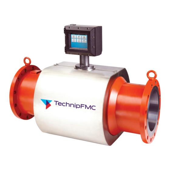
MPU Series C I/O/M Manual Product Overview 2 – Product Overview The Smith Meter MPUs are multi-path ultrasonic meters with Signal Processing Unit (SPU) for custody transfer or custody transfer accuracy measurement of petroleum products. The following ultrasonic meters are covered under this manual: •... -
Page 12: Transit Time Measurement
MPU Series C I/O/M Manual Product Overview 2.2.1. Transit Time Measurement To measure gas flow and velocity of sound (VOS), the MPU employs the fact that sound travels faster with the gas flow than against it. The figure below shows a top view of a pipe with gas flow. -
Page 13: Travel Time Corrections
θ c − cos( MPU Series C I/O/M Manual Product Overview − ⋅ From these equations one can isolate the gas flow velocity and VOS. Thus: θ cos( − ⋅ θ cos( ⋅ ⋅ 2.2.2. Travel Time Corrections The signal pulse in the transducers is converted from an electrical signal to an acous- tic signal, and back to an electrical signal on the receiver side. -
Page 14: Ultra Series Flowmeter Features
MPU Series C I/O/M Manual Product Overview 2.2.4. MPU Series Flowmeter Features • Custody Transfer Accuracy – The MPUs combine the latest in ultrasonic design, sensitivity analysis, integration methods and signal processing optimization to deliver accurate custody transfer measurement. Measurement Stability – The path configuration and integration algorithms give •... -
Page 15: Operation Of Mpu
MPU Series C I/O/M Manual Operation of MPU 3 – Operation of MPU 3.1. Major Components of the Ultrasonic Flowmeter MPU gas flowmeters consist of the following components: • Meter Body • Measurement Paths • MPU800 consists of 4 measurement paths in four chordal planes •... -
Page 16: Receipt Of Equipment
MPU Series C I/O/M Manual Operation of MPU 3.3. Receipt of Equipment When the equipment is received, the outside packing case should be checked immediately for any shipping damage. If the packing case has been damaged, the local carrier should be notified at once regarding their liability. -
Page 17: Mechanical Inspection
MPU Series C I/O/M Manual Operation of MPU 3.4.1. Mechanical Inspection Preferably, the original protection covers should still be intact. These may now be removed. Before the spool piece is mounted in the pipeline the following must be controlled: • The inside surface must be clean and dry. -
Page 18: Mechanical Installation
MPU Series C I/O/M Manual Operation of MPU 3.5. Mechanical Installation Installation of the MPU flowmeter should follow good piping practices, such as alignment of the pipe center lines before installing the meter in order to minimize compressive, tensile or torsional stresses placed on the meter. A temporary, straight pipe spool can be used to align the process piping prior to meter installation if required. -
Page 19: Mpu 1600 Recommended Installation
MPU Series C I/O/M Manual Operation of MPU 3.7.2. MPU 1600 Recommended Installation The recommended installation for the MPU 1600C is 5D upstream straight run. For opti- mum performance it is recommended to keep partial restrictions or variable flow diversions such as control valves away from the upstream area. -
Page 20: Electrical Installation
MPU Series C I/O/M Manual Operation of MPU 3.8. Electrical Installation Electrical Installation General Requirements (a) It is imperative that the electrical installation be performed by a competent individual that is familiar with associated risks involved with the installation, operation, and main- tenance, of electrical equipment in hazardous (classified) locations. -
Page 21: For Atex And Iec Ex Installations
CRITICAL: If the MPU is NOT connected to an Ethernet network then TechnipFMC strongly recommends that an Ethernet cable is connected to the UMCB - ETH1 RJ45 connector on the meter and is fed into the closest control room. -
Page 22: Installation Of Cables
MPU Series C I/O/M Manual Operation Fiber Optics Communication: This device contains a fiber optic Ethernet Transceiver module; any fiber optics device(s) connected to this device through the connecting fiber optic cable must be suitable for the location in which it is (they are) installed and any locations where the fiber optic cables are run, with respect to both electrical circuits and optical radiation, for ATEX and/or IEC Ex installations. -
Page 23: Equipment Required
MPU Series C I/O/M Manual Operation 3.9.1.1. Equipment Required • Conventional hand tools for cable installation. • If a fiber optic cable is a part of the delivery, special tools for connecting ST-connectors are required. CAUTION: To prevent ignition of hazardous atmospheres, disconnect from supply circuit before opening, keep tightly closed when circuits are in operation. -
Page 24: Transducer Wiring
MPU Series C I/O/M Manual Operation Gland Nut Cable Armoring Connected to Gland Gasket Cone Gland Part 1 Gland Part 2 Example of EEx d Cable Gland Connection (European Model) 3.10. Transducer Wiring The transducer wiring is factory mounted. UMCB-W Connector-PATHx Position Function B-Sig... -
Page 25: Explosion-Proof Housing Closure
IP 65 ingress protection rating. Grease cover flange with petroleum jelly or TechnipFMC grease (P/N 644886401) before attachment of the cover to the housing. 2. Verify the mating areas between the front cover and the main housing are not scratched, corroded or otherwise damaged such that the surface contact between them would be compromised. - Page 26 VIII. Inspect to see that the environmental O-ring is correctly installed (seated into the groove) and in good condition, no cracks etc., if defective replace to maintain environmental protection. Grease cover flange with petroleum jelly or TechnipFMC grease (P/N 644886401) before reattachment of the cover to the housing.
-
Page 27: Umcb
MPU Series C I/O/M Manual UMCB – Ultrasonic Meter Control Board 4 – UMCB (Ultrasonic Meter Control Board) NOTE: On the UMCB cover shield legends position 1 is indicated by a circle enclosed in a square. 4.1. Wiring Examples/Information 4.1.1. Power Supply The electronics are designed to be powered by 24 VDC. -
Page 28: Digital I/O
MPU Series C I/O/M Manual UMCB – Ultrasonic Meter Control Board NOTE: Reference the product specification sheets for technical specifications of the I/O. Note in diagrams below: Customer Wiring / Equipment 4.1.3. Digital I/O Connections for the digital I/O are made on the UMCB board using terminal CN2 and CN3 4.1.4. -
Page 29: Digital Inputs
MPU Series C I/O/M Manual UMCB – Ultrasonic Meter Control Board Digital Outputs - Active Output Mode Externally Powered Pull Up Addendum SW600 Unregulated +VDC +VDC (from CN1) 1 kΩ 1 watt Pulse In 1 +VDC EARTH 1 kΩ 1 watt Pulse In 2 *SW600 Positions 1 and 2 must be set to OFF **If using dual pulse output the two conductors... -
Page 30: Weights & Measures Lock
MPU Series C I/O/M Manual UMCB – Ultrasonic Meter Control Board Digital In #2 is currently dedicated to the use as an external Weights and Measures hardware lock switch. Consult the factory for the available uses for Digital In #1. Digital IN +VDC 1.67K... -
Page 31: Analog Outputs
MPU Series C I/O/M Manual UMCB – Ultrasonic Meter Control Board Input Signal Ranges 4-20mA In #1 and #2 3.8 - 22 mA 76.7278 - 168.4783Ω Black Black EARTH 4-20 mA IN2 4.1.8. Analog Outputs Connections for the Analog Output are made on the UMCB board using terminal CN5: Function Connection Port 4-20mA In #1... -
Page 32: Communications
MPU Series C I/O/M Manual UMCB – Ultrasonic Meter Control Board Output Signal Range: 3.8 - 21.0mA 4-20 Out +VDC Analog IN EARTH 4.2. Communications 4.2.1. Ethernet The 10/100 base-T Ethernet connections are made using terminal ETH1 and ETH3. Fiber optic connection is made using terminal ETH2 Comm. -
Page 33: Rs-485
Modbus-RTU communications can be found in the Communications Manual. 4.2.4. A USB female A connector is provided on the UMCB for connection to TechnipFMC approved devices only. Connection of unauthorized devices may result in unexpected meter behavior, damage to the electronics, and a voided warranty. Do not connect anything unless directed to by the factory. - Page 34 Page intentionally left blank. Page 34 • MNKS025 ║ Issue/Rev. 0.1 (11/18)
-
Page 35: Meter Start-Up
MPU Series C I/O/M Manual Meter Start-Up 5 – Meter Start-Up Before powering on the meter and beginning flow measurement, verify that the following items are completed: • Meter has been properly installed (flow direction is correct) in the piping and all connections are free from leaks. -
Page 36: Led Behavior
MPU Series C I/O/M Manual Meter Start-Up 5.1.1. LED Behavior 5.1.2. Start-Up During start-up the following LED behavior should be observed: All visible LEDs will briefly flash, then all shutoff except yellow. Yellow shuts off when the main OS starts booting. 5.1.3. - Page 37 1. Install the latest version of Bonjour: 2. The Bonjour browser will show devices on the network as indicated below. Identify the meter as the device listed as a TechnipFMC Ultrasonic Meter 3. Use the Serial number to “Ping” the meter from the command prompt as per Section B instructions above.
- Page 38 Page intentionally left blank. Page 38 • MNKS025 ║ Issue/Rev. 0.1 (11/18)
-
Page 39: Web User Interface
MPU Series C I/O/M Manual Web User Interface 6 – Web User Interface 6.1. Main Menu The MPU Series C main menu offers the ability to navigate anywhere on the user interface and offers large buttons that are easy to press along with icons that are easily recognized. -
Page 40: Path Flow
MPU Series C I/O/M Manual Web User Interface 6.3.1. Path Flow (Path: Overview > Path Flow) The Path Flow Tab shows the flow velocity, VOS (velocity of sound) and turbulence per path of the meter. 6.3.2. Path Signals (Path: Overview > Path Signals) The Path Signals Tab shows SNR (Signal Noise Ratio) Raw, SNR Used, Signal % and Gain per path per channel. -
Page 41: Accumulators
MPU Series C I/O/M Manual Web User Interface 6.3.3. Accumulators (Path: Overview > Accumulators) The Accumulators Tab shows Forward and Reverse Volume Totalizers; Forward and Reverse Error Volume Totalizers for the meter. 6.3.4. History Chart (Path: Overview > History Chart) History Chart Tab illustrates Flow Velocity and VOS (Velocity of Sound) trending. -
Page 42: Setting Menu
MPU Series C I/O/M Manual Web User Interface 6.4. Settings Menu When the Settings Button Icon is selected, a Login Screen will appear. A password is required to access the configuration settings. There are (5) different levels of security access for the meter and each have the following default passwords: •... -
Page 43: General
MPU Series C I/O/M Manual Web User Interface Page 1 Page 2 6.4.2.1. General 6.4.2.1.1. Account Administration (Path: Settings > General > Account Administration) Password modifications are accomplished here. The user level currently logged in is capable of changing its own password and any user level lower. (e.g. A user logged in at level 3 may change the password for levels 1-3). -
Page 44: Date/Time
MPU Series C I/O/M Manual Web User Interface 6.4.2.1.2. Date/Time (Path: Settings > General > Date/Time) The system date and time follow the international UTC standard. • Button – save the current selection, exit dialog • Button – discard changes, exit dialog 6.4.2.1.3. -
Page 45: Network Settings
MPU Series C I/O/M Manual Web User Interface 6.4.2.2. Network Settings (Path: Settings > Network Settings) Configure the necessary Ethernet settings for network communication. • DHCP – Meter will automatically be assigned an IP per the network's DNCP server. • Fixed –... - Page 46 MPU Series C I/O/M Manual Web User Interface 6) The last configured node in the list before an un-configured node sets the meter factor for all flow rates above that flow rate. • Lock Icon – Indicates the security level required to modify the current setting •...
-
Page 47: Communications
MPU Series C I/O/M Manual Web User Interface 6.4.2.4. Communications (Path: Settings > Communications) This menu provides configuration options for the meter's only serial port (CN4). 6.4.2.4.1. Serial Port Function (Path: Settings > Communications > Serial Port Function) This option determines the primary functionality for the serial port (CN4). Options: •... -
Page 48: Baud Rate Selection
MPU Series C I/O/M Manual Web User Interface 6.4.2.4.2. Baud Rate Selection (Path: Settings > Communications > Baud Rate Selection) This option sets the serial port's rate of communication. Options: • 1200 Baud • 19200 Baud • 2400 Baud • 38400 Baud •... -
Page 49: Word Length Selection
MPU Series C I/O/M Manual Web User Interface 6.4.2.4.4. Word Length Selection (Path: Settings > Communications > Word Length Selection) This option determines the word length for the serial port. Options: • 7 bits • 8 bits 6.4.2.4.5. Stop Bit Selection (Path: Settings >... -
Page 50: Modbus Unit Id
MPU Series C I/O/M Manual Web User Interface 6.4.2.4.6. Modbus Unit ID (Path: Settings > Communications > Modbus Unit ID) This parameter sets a unique address for the Modbus functionality to utilize during communications. • Input Field – desired address (must match Modbus Master Device) 6.4.2.4.7. -
Page 51: Meter Tag
MPU Series C I/O/M Manual Web User Interface 6.4.2.4.8. Meter Tag (Path: Settings > Communications > Meter Tag) This parameter provides the meter with a unique identifier for ease of distinguishing between it and other potential meters on the network. This tag is visible in the top-right corner of the Main Menu and Overview screens. -
Page 52: Modbus Nan Subtitution Value
Options: • • Avg Period, with Avg • Avg Period without Avg It is recommended to keep the factory default setting for this parameter unless otherwise instructed by an authorized TechnipFMC Engineer. Page 52 • MNKS025 ║ Issue/Rev. 0.1 (11/18) -
Page 53: Signal Logging Interval
• 10 Minutes • 1 Hour • 8 Hours • 1 Day It is recommended to keep the factory default setting for this parameter unless otherwise instructed by an authorized TechnipFMC Engineer. Issue/Rev. 0.1 (11/18) ║ MNKS025 • Page 53... -
Page 54: Factory Settings
MPU Series C I/O/M Manual Web User Inteface 6.4.2.6. Factory Settings (Path: Settings > Factory Settings) The data that is in this section is installed at the Factory. Do not attempt to change any values without pre-authorization. 6.4.2.7. Meter Body (Path: Settings >... -
Page 55: Max Vos Deviation
MPU Series C I/O/M Manual Web User Inteface 6.4.2.9.3. Max VOS Deviation Maximum deviation between the measured velocity of sound on any two paths. The value is set by the factory and not typically adjusted unless otherwise instructed. 6.4.2.9.4. Min Signal to Noise Ratio Signal to Noise Ratio measures the amount of signal noise being measured with the ultrasonic sound signals. -
Page 56: Enable Confidence Alarms
MPU Series C I/O/M Manual Web User Interface 6.4.2.9.12. Enable Confidence Alarms The confidence alarms provide an indication of the measurement quality for a number of meter outputs. These alarms output through Modbus measurement health status word only. The input to enable the alarm is in the format of an eight bit integer that can be used to mask specific bits from activating if desired. -
Page 57: Line Temperature Input Mode
MPU Series C I/O/M Manual Web User Interface This is not typically changed from this menu: this mode is automatically enabled if a particular diagnostic feature is triggered; e.g. Simulate Flow. 6.4.2.10.3. Line Temperature Input Mode (Path: Settings > Modes > Line Temperature Input Mode) This option determines the source of the temperature compensation value. -
Page 58: Line Pressure Input Mode
MPU Seriec C I/O/M Manual Web User Interface 6.4.2.10.4. Line Pressure Input Mode (Path: Settings > Modes > Line Pressure Input Mode) This option determines the source of the pressure compensation value. Options: • Fallback – (programmed value) • 4-20 mA Input #1 – (live input value) •... -
Page 59: Line Pressure Fallback Value
MPU Series C I/O/M Manual Web User Interface 6.4.2.10.6. Line Pressure Fallback Value (Path: Settings > Modes > Line Pressure Fallback Value) This value is used in temperature compensation calculations; the Line Pressure Input Mode setting must be configured for Fallback in order to utilize this value. •... -
Page 60: Diagnostic Mode
MPU Series C I/O/M Manual Web User Interface 6.4.2.10.9. Diagnostic Mode (Path: Settings > Modes > Diagnostic Mode) Diagnostic mode allows the meter to be set into a bench test simulation mode. This setting eliminates actual flow measurement and replaces it with the selected simulated flow outputs. -
Page 61: Loopback Flow Velocity
MPU Series C I/O/M Manual Web User Interface 6.4.2.10.10. Loopback Flow Velocity (Path: Settings > Modes > Loopback Flow Velocity) Sets the simulated velocity to be used in the loopback mode simulation 6.4.2.10.11. Loopback Velocity of Sound (Path: Settings > Modes > Loopback Velocity of Sound) Sets the simulated velocity of sound to be used in the loopback mode simulation Issue/Rev. -
Page 62: Loopback Flow Profile
MPU Series C I/O/M Manual Web User Interface 6.4.2. 1 0. 1 2. Loopback Flow Profile (Path: Settings > Modes > Loopback Flow Profile) Sets the simulated flow profile to be used in the loopback mode simulation 6.4.2.11. Signal (Path: Settings > Signal) The data that is in this section is installed at the Factory. -
Page 63: Alarms Menu
MPU Series C I/O/M Manual Web User Interface 6.5. Alarms Menu The Alarms Button leads from the main menu to the Alarms Screen. This screen displays the 10 most recent active alarms. These alarms are dynamically updated and cleared as the conditions are corrected. 6.6. -
Page 64: Path Data
MPU Series C I/O/M Manual Web User Interface 6.6.1.1. Path Data (Path: Run Data > Path Data) This section shows the data for each individual path. Some of this information is also located on the Overview Path Flow screen. Page 64 • MNKS025 ║ Issue/Rev. 0.1 (11/18) -
Page 65: System Data
MPU Series C I/O/M Manual Web User Interface 6.6.1.2. System Data (Path: Run Data > System Data) This section illustrates general system-level data. Some of this information is also located on the Overview screen. 6.6.1.3. Computation Data (Path: Run Data > Computation Data) This section exhibitions physical property data calculated within the meter. -
Page 66: Monitoring
MPU Series C I/O/M Manual Web User Interface Top-Level Diagnostics Screen This screen contains several meter diagnostic features partitioned into groups. Some of these menu options are user-interface-dependent and will be hidden if not supported. On a local touchscreen display, the Upload Program Parameters, Download Program Parameters, and the Update Software options are hidden. -
Page 67: Logs
MPU Series C I/O/M Manual Web User Interface 6.7.1.2. Logs (Path: Diagnostics > Monitoring > Logs) This menu provides access to the following: • Weights and Measures Log --> stored data entries • Alarm Log --> stored data entries • Event Log --> stored data entries •... -
Page 68: Alarm Log
MPU Series C I/O/M Manual Web User Interface 6.7.1.2.2. Alarm Log (Path: Diagnostics > Monitoring > Logs > Alarm Log) This screen displays all alarm related entries. The entry layout is as follows: Log Entry # Date/Time Entry Description Details 6.7.1.2.3. -
Page 69: Download Logs
MPU Series C I/O/M Manual Web User Interface 6.7.1.2.4. Download Logs (Path: Diagnostics > Monitoring > Logs > Download Logs) This screen provides a method for downloading any of the log files from the meter. To download a log: (1) Select the desired log to download •... -
Page 70: Commissioning
MPU Series C I/O/M Manual Web User Interface (1) Select the desired log to download • The process will initiate automatically • The check box associated with the file will be checked; although [checked the file may be downloaded as many times as desired] •... -
Page 71: Analog Calibration
MPU Series C I/O/M Manual Web User Interface 6.7.2.1. Analog Calibration (Path: Diagnostics > Commissioning > Analog Calibration) Calibration uses a wizard type program to adjust the analog and RTD inputs for zero and span for optimum accuracy. 6.7.2.1.1. Example Non-RTD Calibration Apply test inputs to meter The calibration can now be tested. -
Page 72: Example Rtd Calibration
MPU Series C I/O/M Manual Web User Interface 6.7.2.1.2. Example RTD Calibration Apply test inputs to meter The calibration can now be tested. Apply an actual signal to the meter press “Test” to check if the meter reads the correct value. Enter “Submit” to enter new factors if the calibration was successful. -
Page 73: Simulate Analog Output
MPU Series C I/O/M Manual Web User Interface 6.7.2.3. Simulate Analog Output (Path: Diagnostics > Commissioning > Simulate Analog Output) This option places the meter into a simulated ("forced") state and sets the output current (CN5) to the value set here. •... -
Page 74: Force Values
MPU Series C I/O/M Manual Web User Interface 6.7.2.5. Force Values (Path: Diagnostics > Commissioning > Force Values) This option used to indicate when the meter is in a simulation ("forced") state. While in this state, the information outputted by the meter may not be the real measured data. This state is meant for simulating flow and forcing desired analog and pulse output values. - Page 75 MPU Series C I/O/M Manual Web User Interface The following data is included in the Parameter Listing document: Meter Information: Meter type Meter tag Electronics Serial # Software revision # Checksums: Parameter, Ultrasonic, DSP and Modbus Network settings: IP Address, Netmask, Network, Gateway Communications Serial port function Baud Rate selection...
-
Page 76: Download Program Parameters
MPU Series C I/O/M Manual Web User Interface Modes: Manually disabled paths Manually forced outputs Line temperature correction settings Line pressure correction settings Electronic sealing mode Electronic seal state Diagnostic mode Signal: Signal type, frequency and filter settings Transducer: Port Numbers and Transducer Delays Type, Nodes and Correction Modes Node temperatures and pressures 6.7.5. -
Page 77: Update Software
MPU Series C I/O/M Manual Web User Interface 6.7.7. Update Software (Path: Diagnostics > Update Software) This feature is used to update the software within a meter. This process will reboot the meter upon completion. During the reboot period, the meter will be without measurement functionality. -
Page 78: Reset Passwords
MPU Series C I/O/M Manual Web User Interface 6.7.8. Reset Passwords (Path: Diagnostics > Reset Passwords) This selection resets all passwords to the factory default values in case the user defined passwords have been lost. In order to reset passwords, the meter must be opened in order to set the rotary dip switch. -
Page 79: Software Sealing
MPU Series C I/O/M Manual Web User Interface Inside the enclosure digital input #2, which is located on terminal strip CN2 terminals 3 and 4, provides the hardware seal. The meter is shipped from the factory with a jumper (J_WM) across the terminals. When removed, no legally relevant parameters may be changed. -
Page 80: Meter Information
MPU Series C I/O/M Manual Web User Interface 6.9. Meter Information This screen provides pertinent meter information in regards to electronics software and hardware properties. • Type – style of meter; e.g. Ultra 8c, Ultra 6c, etc. • Tag ID – the unique identifier given to this particular meter •... -
Page 81: Integrated Touch Screen Display
MPU Series C I/O/M Manual Integrated Touch Screen Display 7 – Integrated Touch Screen Display The MPU Series flowmeter integrated display is a touch screen device that functions as a complete HMI equivalent to a remote connection by PC. It allows complete access to interfaces to the web based user interface functions from Chapter 5. -
Page 82: Connection To Ultrasonic Meter Control Board
If a host serial number is configured, the display will search the network for a TechnipFMC device with the specified serial number, obtain an IP address, and attempt to connect with that host. If it fails with the device serial number it will attempt to connect to the secondary URL. -
Page 83: Display Configuration
MPU Series C I/O/M Manual Integrated Touch Screen Display 7.3.1.1. Display Configuration The configuration tab is used to set up the display to communicate with the desired device and to set the password to control access of the display settings. A password is required to access the configuration settings. -
Page 84: Display Configuration - General
MPU Series C I/O/M Manual Integrated Touch Screen Display 7.3.1.2. Display Configuration - General Date/Time – Adjust the date and time of the display unit. Once the display has been sealed the date and time adjustment will be locked out. Set Passwords –... -
Page 85: Display Connections
MPU Series C I/O/M Manual Integrated Touch Screen Display 7.3.1.4. Display Connections The connections setting is used to connect to the desired ultrasonic flowmeter. Primary URL – This fixes a target IP/URL address that the Display will first attempt to connect to upon startup of the unit. -
Page 86: Display Modes
MPU Series C I/O/M Manual Integrated Touch Screen Display 7.3.1.5. Display Modes The Modes setting is used configure the set the electronic seal and to configure the backlighting sleep mode for the display. Electronic Seal State This is used to set the electronic seal onto the display unit. Sealing locks out the adjustment of parameters that would be required to be fixed by a weights and measures official. -
Page 87: Display Maintenance Settings
Weights and Measures control, it will need inspected and sealed again. Order a USB adapter cable from TechnipFMC; this cable connects to CN3 and presents a standard type A USB connector. -
Page 88: Display Reconnect
MPU Series C I/O/M Manual Integrated Touch Screen Display The entry layout is as follows: Log Entry # Timestamp Entry Type Description of Change 7.3.4. Display Reconnect The Reconnect button initiates an attempt to connect to configured devices using the same sequence used during power up. - Page 89 MPU Series C I/O/M Manual Integrated Touch Screen Display 2. Configure the display. • Select Configuration • Select Security Level 5 • Enter 4-digit pin [default is 5555] Issue/Rev. 0.1 (11/18) ║ MNKS025 • Page 89...
- Page 90 Ultra Series C I/O/M Manual Integrated Touch Screen Display • Select the blue find button • The display will find the UMCB unique identifier serial number. • Press the return key (upper left hand corner) • The serial number is shown in the display dialog box. Write this number down for future reference.
- Page 91 MPU Series C I/O/M Manual Integrated Touch Screen Display 3. Change the display passwords. • Select General • Select Set Passwords • Select Security Level 5 • Put in new security code • Select Save • SUCCESS message is displayed. Touch the display anywhere to acknowledge the success message.
- Page 92 MPU Series C I/O/M Manual Integrated Touch Screen Display • Select Configuration • Select Security Level 5 and sign in • Select Modes • Select Electronic Seal State • Select the drop down • Select Sealed • Press green accept button Page 92 •...
- Page 93 MPU Series C I/O/M Manual Integrated Touch Screen Display 5. Verify software seal. • Select Information • Verify that the Parameter Seal shows a closed lock • Select the back button in the upper left hand corner of the display •...
- Page 94 MPU Series C I/O/M Manual Integrated Touch Screen Display 7. Verify the connection parameters only allow the display to connect with devices that are part of the Legally Relevant system. • Select Reconnect • Verify that the serial number written down earlier is shown in the upper left hand corner of the meter display overview screen.
- Page 95 MPU Series C I/O/M Manual Integrated Touch Screen Display • Enter 4-digit pin [default is 5555] • Press Login • Press Connections • Select Primary URL • Select the dialog box • Enter the Primary URL (address of the meter assigned during meter setup) using the on-screen alphanumeric keyboard EX: http://192.168.181.7 •...
- Page 96 MPU Series C I/O/M Manual Integrated Touch Screen Display • Select Secondary URL • Ensure no data is entered in the dialog box • Press green accept button • Press down arrow in upper right hand corner • Select Secondary Timeout •...
-
Page 97: Display Network Configuration
MPU Series C I/O/M Manual Integrated Touch Screen Display 6. For a remote display, inspect the connections to the display; verify there are NO connections to the display except for power (CN4) and Ethernet (ETH1). Any other connections to the display are not allowed as they compromise security. Bolt the enclosure closed and apply a seal wire such that it must be destroyed to open the enclosure again. - Page 98 Page intentionally left blank. Page 98 • MNKS025 ║ Issue/Rev. 0.1 (11/18)
-
Page 99: Fluid Correction Configuration
MPU Series C I/O/M Manual Fluid Correction Configuration 8 – Fluid Correction Configuration This section addresses configuring the meter for fluid correction calculations; this consists of selecting an algorithm and assigning inputs from various sources. The correction results may be seen in the fluid correction run screen and accumulators screen. -
Page 100: Gost (Gas Meter Only)
MPU Series C I/O/M Manual Fluid Correction Configuration 8.1. GOST (Gas Meter Only) Content outline Calculation description a. GOST standard: GOST 30319.2-2015 b. Heat energy equations used Superior: Н = 92,819 ( 0,51447ρc + 0,05603 - 0,65689хa - хy ) Inferior: Н... - Page 101 MPU Series C I/O/M Manual Fluid Correction Configuration b. Pressure (default units: bar) c. Reference density (default units: kg/m3) d. Gas content mole fractions (units: %) Issue/Rev. 0.1 (11/18) ║ MNKS025 • Page 101...
- Page 102 MPU Series C I/O/M Manual Fluid Correction Configuration Nitrogen Carbon Dioxide Enabling GOST calculations a. Selecting the GOST algorithm Page 102 • MNKS025 ║ Issue/Rev. 0.1 (11/18)
- Page 103 MPU Series C I/O/M Manual Fluid Correction Configuration GOST calculation outputs Select Run Data from Main Menu Select GOST Calculations Output to view Run Time Data to verify input and output values. a. User Screens Run Data / GOST Calculation Output c.
- Page 104 MPU Series C I/O/M Manual Fluid Correction Configuration a. Selectable on analog output b. Selectable on pulse output Under Settings in the Main Menu, go to Inputs and Outputs. Select Analog Output Function for standard flowrate. The Standard Volume Flow Rate selection is a new feature for software versions 1.9 and above.
-
Page 105: Language Selection
MPU Series C I/O/M Manual Web User Interface 9 – Language Selection GOST (Gas Meter Only) English or Russian is selectable through the overview screen. Reference Section 6.4 to access the Settings Menu. Issue/Rev. 0.1 (11/18) ║ MNKS025 • Page 105... - Page 106 Page intentionally left blank. Page 106 • MNKS025 ║ Issue/Rev. 0.1 (11/18)
-
Page 107: Maintenance
MPU Series C I/O/M Manual Maintenance 10 – Maintenance The purpose of this section is to give the user applicable information regarding maintenance of the MPU, to maintain the warranty requirements arranged. In addition, to make sure that the user can perform replacement and repair safe and quickly on his own, is all replacement/repair procedures that is relevant for the equipment presented in this section. -
Page 108: Replacement Of Transducers
MPU Series C I/O/M Manual Maintenance Troubleshooting and Replacement of Parts CAUTION: Trouble shooting and replacement outside of what is described in this manual, require special skills. Any replacement of parts must only be performed by personnel with the required knowledge. -
Page 109: Recommended Clock Battery Replacement Interval - 5 Years When Meter Is In Service
5. Remove the four mounting screws from the UMCB. 6. Remove the old battery and replace battery with ENERGIZER P/N CR2032 (substitutes not allowed), TechnipFMC P/N 644581418. 7. Place the UMCB assembly back into enclosure and secure with the four mounting screws. -
Page 110: Storage And Preservation Of The Mpu And Spare Parts
MPU Series C I/O/M Manual Maintenance Batter Type CR 2032 3V WARNING: Breaking the physical seals and changing the hardware lock from closed to open should only be done when approved by the authorities having jurisdiction. 10.5. Storage and Preservation of the MPU and Spare Parts SHORT Term Storage –... - Page 111 MPU Series C I/O/M Manual Maintenance Preservation For preservation of the meter, the following is required: • Cortech or a similar corrosion inhibitor to prevent degradation of the spool. • Covers for the flanges, to protect against mechanical damage. • Necessary supports and extra covers to secure against damage caused by handling of other equipment.
- Page 112 Page intentionally left blank. Page 112 • MNKS025 ║ Issue/Rev. 0.1 (11/18)
-
Page 113: Address And Contact Information
+49 (0)4101 304 - 0 (Switchboard) Fax: +49 (0)4101 304 - 152 (Service) Fax: +49 (0)4101 304 - 133 (Sales) Fax: +49 (0)4101 304 - 255 (Order processing) E-Mail: info.ellerbek@technipfmc.com Web: www.technipfmc.com Issue/Rev. 0.1 (11/18) ║ MNKS025 • Page 113... -
Page 114: Appendix - Description Of Legally Relevant Parameters
MPU Series C I/O/M Manual Appendix A – Description of Legally Relevant Parameters 12 – Appendix – Description of Legally Relevant Parameters MPU Series Meter Database Parameters The following is a list of all parameters. All parameters at security levels 3, 4 and 5 (Commissioning, Owner and Weights and Measures) are Legally Relevant;... - Page 115 MPU Series C I/O/M Manual Appendix A – Description of Legally Relevant Parameters Parameter Menu Range Nominal Description Name Diameter Meter Body -None None Specifies spool compensation Compensation -Pipe Model algorithm to use for p/t correction Mode of spool dimensions. Meter Type Meter Body -Ultra4...
- Page 116 MPU Series C I/O/M Manual Appendix A – Description of Legally Relevant Parameters Parameter Menu Range Nominal Description Name An In Low Limit Inputs and 3.8 mA 3.8 mA Electrical input below this limit will Outputs 12 mA not be allowed. RTD In Inputs and -10 C...
- Page 117 MPU Series C I/O/M Manual Appendix A – Description of Legally Relevant Parameters Parameter Menu Range Nominal Description Name Meter Tag Communications Up to 16 (factory set to electronics Unique tag name designated for this characters serial number) meter; used for identification. Max Velocity of Limits 300 m/s...
- Page 118 MPU Series C I/O/M Manual Appendix A – Description of Legally Relevant Parameters Parameter Menu Range Nominal Description Name Word Length Communications -7 bits -8 bits Select the serial port word length. Selection -8 bits Stop Bit Communications Select the serial port stop bits. Selection Ethernet Network...
- Page 119 Page intentionally left blank. Issue/Rev. 0.1 (11/18) ║ MNKS025 • Page 119...
-
Page 120: Related Publications
Otherwise, the manufacturer assumes no responsibility for the use of specifications which may have been changed and are no longer in effect. Contact information is subject to change. For the most current contact information, visit our website at TechnipFMC.com and click on the “Contact Us” link.
Need help?
Do you have a question about the Smith Meter MPU C Series and is the answer not in the manual?
Questions and answers