Advertisement
MANUAL
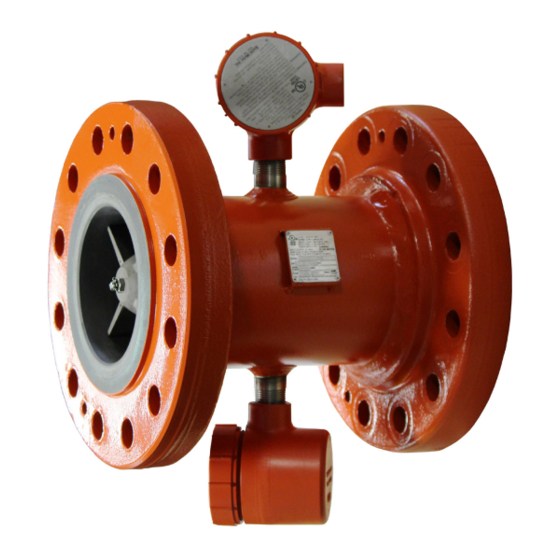
Smith Meter
Turbine Meters
®
Models 4" through 24" Sentry Turbine Meters
Service Manual
Bulletin MN02004 Issue/Rev 0.3 (8/02)
Contents
Section 1 - General Information ................................................................................................................. Page 2
Return Procedures ......................................................................................................................................... Page 2
Section 2 - Service ....................................................................................................................................... Page 3
Section 3 - Troubleshooting Guide ............................................................................................................ Page 9
Section 4 - Maintenance and Calibration Record ................................................................................... Page 10
Section 5 - Related Publications ...............................................................................................................Page 11
Advertisement

Related Manuals for TechnipFMC Smith Meter


Summary of Contents for TechnipFMC Smith Meter
-
Page 1: Table Of Contents
MANUAL Smith Meter Turbine Meters ® Models 4" through 24" Sentry Turbine Meters Service Manual Bulletin MN02004 Issue/Rev 0.3 (8/02) Contents Section 1 – General Information ......................... Page 2 Return Procedures ............................Page 2 Section 2 – Service ............................Page 3 Section 3 –... -
Page 2: Section 1 - General Information
Refer to the nameplate on the side All items to be returned must be freight prepaid to the of the meter. TechnipFMC 1602 Wagner Avenue, Erie, Pennsylvania 16514 and shipped in accordance with all rules and 2. Check pick-up coil and preamplifier for proper regulations of the Department of Transportation and operation. -
Page 3: Section 2 - Service
Section 2 – Service Removal and Replacement of Pick-Up Caution: Tighten pick-up coil finger tight. Over tightening will result in damage to coil. Coil With Meter in Product Line 1. Make certain power has been disconnected to Removal and Replacement of Preamplifier meter. - Page 4 Section 2 – Service (continued) 3. Disconnect output wiring and remove preamp from junction box, Figure 6. 4. For reassembly, reverse procedures. Figure 8 8. Remove downstream stator, Figure 9. In a unidirectional turbine meter, the stator is located by a Woodruff key. Care should be taken that the Woodruff key is not lost.
- Page 5 Section 2 – Service (continued) If thrust washer shows signs of wear but is not 11. Should rotor bearing require replacing, it is cracked, turn washer over. suggested that rotor assembly be returned to Measurement Solutions for rework. See “Return •...
- Page 6 Section 2 – Service (continued) Note: It will be necessary to remove one deflector ring Table 1 – Shaft Nut Torque Values when servicing a bidirectional turbine meter. Meter Sizes Thread Size Torque Required (Lubricated) ±5% 4" #10-32 UNF-2 22 in-lb 6", 8"...
- Page 7 Section 2 – Service (continued) 10. Place turbine meter in horizontal position, Figure 18. Hold either up or downstream stator and move internal laterally. Assembly should move approximately 0.010" to 0.032". If assembly has lateral movement or end play, this indicates platform bearing is securely locked in place.
- Page 8 Section 2 – Service (continued) Test After meter has been inserted into the product line, meter must be proved in order to obtain new meter factor. This is usually accomplished by the use of a displacement-type prover. During testing, should repeatability not be obtainable, check to make certain that pick-up coil is tight.
-
Page 9: Section 3 - Troubleshooting Guide
Section 3 – Troubleshooting Guide For maximum accuracy, the meter must be recalibrated after each repair. Problem Probable Cause Corrective Action Overdelivery Dirty bearings. Clean. (or under registration) Worn bearings. Replace. Corrosion, erosion. • Minor: Reprove meter. • Extreme: Replace damaged parts. Bent blades. -
Page 10: Section 4 - Maintenance And Calibration Record
Section 4 – Maintenance and Calibration Record Maintenance and Calibration Record Meter No. Meter No. Serial No. Serial No. Product Product Flow Rate Flow Rate "K" Factor "K" Factor Date Proved Date Proved Remarks Remarks Meter No. Meter No. Serial No. Serial No. -
Page 11: Section 5 - Related Publications
Section 5 – Related Publications The following literature can be obtained from Measurement and Product Solutions Literature Fulfillment at measure- ment.fulfillment@technipfmc.com or online at http://info.smithmeter.com/literature/online_index.html. When requesting literature from Literature Fulfillment, please reference the appropriate bulletin number and title. Turbine Meters Manual 4"... - Page 12 Erie, Pennsylvania 16510 USA P:+1 814.898.5000 TechnipFMC Germany Operation Smith Meter GmbH 13460 Lockwood Rd. Regentstrasse 1 Building S01 TechnipFMC.com 25474 Ellerbek, Germany Houston, Texas 77044 USA P:+49 4101 304.0 P:+1 281.591.4000 © 2020 TechnipFMC plc. All rights reserved. MN02004 Issue/Rev. 0.3 (8/02)
Need help?
Do you have a question about the Smith Meter and is the answer not in the manual?
Questions and answers