
Related Manuals for TechnipFMC Smith Meter JB10 S1


Summary of Contents for TechnipFMC Smith Meter JB10 S1
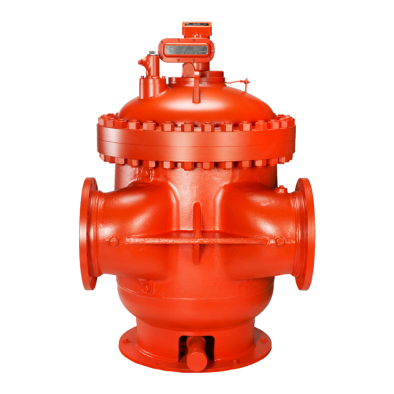
- Page 1 MANUAL Smith Meter Rotary Vane PD Meters ® Smith Meter 3-Bladed Double Case ® PD Meters Service Manual Bulletin MN01006 Issue/Rev 0.4 (12/18) Models JB10 - S1, S3, S5, S6, S7, and S8 K12 - S3, S5, S6, and S7 M16 - S3, S5, and S6...
- Page 2 All information and technical specifications in this documentation have been carefully checked and compiled by the author. However, we cannot completely exclude the possibility of errors and are always grateful to be informed of these errors. Smith Meter is a registered trademark of TechnipFMC. ® Customer Support Contact Information:...
-
Page 3: Table Of Contents
3-Bladed Double Case PD Meters Service Manual Table of Contents Table of Contents 1 – Overview/Introduction..........5 1.1. – Description..............5 2 – Meter Disassembly ............7 2.1. – General ..............7 2.2. – High Pressure Packing Gland Maintenance ....7 2.3. - Page 4 3-Bladed Double Case PD Meters Service Manual Table of Contents This page left intentionally blank. Page 4 • MN01006 ║ Issue/Rev. 0.4 (12/18)
-
Page 5: Overview/Introduction
3-Bladed Double Case PD Meters Service Manual Introduction 1 – Overview This manual provides detailed inspection and service information for the models of Smith Meter ® Double Case, 3-bladed Rotary Meters listed. See related publication for Specifications, Part Lists, and Installation/Operation information pertaining to your specific model of meter. Double case meter construction features ease of maintenance and service. - Page 6 This page left intentionally blank. Page 6 • MN01006 ║ Issue/Rev. 0.4 (12/18)
-
Page 7: Meter Disassembly
3-Bladed Double Case PD Meters Service Manual Meter Disassembly 2 – Meter Disassembly General To assure adequate inspection and maintenance, the step-by-step procedures in this manual should be carefully followed. To gain a better understanding of high capacity rotary meter design and construction, it is suggested that the serviceman review this manual before starting disassem- bly. -
Page 8: Removing Inner Unit From Housing
3-Bladed Double Case PD Meters Service Manual Meter Disassembly 2.4. Removing Inner Unit from Housing With all accessory equipment and the adapter removed from the top cover of the housing, lift the packing gland assembly from its location, Figure 4A. •... -
Page 9: Removing Inner Unit Cover
3-Bladed Double Case PD Meters Service Manual Meter Disassembly Remove the locking bolts from the outer housing. Lift inner unit from housing, Figure 8, and set on level floor. • The M16 has two (2) locking bolts located at the top and bottom of the outlet nozzle. •... - Page 10 3-Bladed Double Case PD Meters Service Manual Meter Disassembly Remove screws and lift adjusting screw cap from cover, Figure 12. • It may be necessary to loosen the cap with a “soft” hammer. Figure 12 Figure 13 Loosen and remove upper shaft nut from shaft, Figure 13. The shaft cone is removed by driving a screwdriver into the slot as shown in Figure 14.
-
Page 11: Rotor Assembly Removal
3-Bladed Double Case PD Meters Service Manual Meter Disassembly Remove jackshaft gear assembly. Use “back up” when removing pin to prevent damage to shaft, Figure 17. • Use “back up” when reassembling also. • Inspect fit of jackshaft in bushings of jackshaft sleeve assembly for excessive wear. •... - Page 12 3-Bladed Double Case PD Meters Service Manual Meter Disassembly With the rotor bottomed, forcibly turn rotor until a blade is in the measuring chamber between the indentations in the meter case, Figure 21. • If spider is used, do not bottom rotor. •...
-
Page 13: Rotor Disassembly
3-Bladed Double Case PD Meters Service Manual Meter Disassembly 11. Insert an eyebolt into tapped hole in bottom end of rotor shaft (shaft nut with loop for the JB10). Raise rotor assembly and set on a suitable wooden block or metal plate, Figure 25 (see Page 7). - Page 14 3-Bladed Double Case PD Meters Service Manual Meter Disassembly The blades are matched to their own rotor slots. Therefore, before removing the blades from the rotor, the blades and rotor slots must be match-marked. • Figure 30 shows one method of marking rotor and blade. Using a 3-corner file, notch first blade (on the back end) and area on rotor next to blade, with one notch, Figure 31.
- Page 15 3-Bladed Double Case PD Meters Service Manual Meter Disassembly Remove adjusting collar, Figure 35. • When removing last screw from collar, support the collar so that it will not drop. With adjusting collar completely removed, lower the assembly back into the rotor and remove clamp.
-
Page 16: Disassembly Of Cam Shaft
3-Bladed Double Case PD Meters Service Manual Meter Disassembly 2.8. Disassembly of Cam Shaft The lock roll pin is removed from the adjusting bar by driving it out of the adjusting block with a drift pin punch, Figure 40. The adjusting screw is removed from the shaft. •... -
Page 17: Disassembly Of Blade Rollers
3-Bladed Double Case PD Meters Service Manual Meter Disassembly 2.9. Disassembly of Blade Rollers With cotter pin removed from blade, Figure 44, insert an Allen wrench and unscrew the socket head screw. Figure 44 Figure 45 Figure 46 Using a machine screw of appropriate size and length and a washer, jack end plug from assembly, Figure 45. -
Page 18: Disassembly Of Rotor Gear Plate Assembly
3-Bladed Double Case PD Meters Service Manual Meter Disassembly 2.10. Disassembly of Rotor Gear Plate Assembly Should inspection or repairs of the rotor gear plate assembly be required, the assembly can be removed without disassembling the rotor from the housing. With the rotor upright, cut the seal wire and remove wire and screws from the assembly, Figure 48. -
Page 19: Removal Of Rotor Bearings In Cover Assembly
3-Bladed Double Case PD Meters Service Manual Meter Disassembly • Reinstall the bearing clip which was set aside (Figure 50), using a sufficient amount of heavy grease to hold it in position in the slots of the inner races. Reinstall assembly onto the rotor shaft. •... - Page 20 This page left intentionally blank. Page 20 • MN01006 ║ Issue/Rev. 0.4 (12/18)
-
Page 21: Reassembly And Clearance Checks
3-Bladed Double Case PD Meters Service Manual Reassembly and Clearance Checks 3 – Reassembly and Clearance Checks 3.1. Reassembly Reassembly is essentially the reverse of the disassembly procedure. Be sure to observe the reassembly precautions noted during tear down of the unit. Should it become necessary to install a new rotor assembly into a meter, check rotor to block clearances, refer to Clearance Guide Table, Page 27. - Page 22 3-Bladed Double Case PD Meters Service Manual Reassembly and Clearance Checks • After all the blade ends have been dressed down, reinstall rotor assembly back into the inner housing. Recheck clearances. • If not enough metal is removed the first time, the process must be repeated until the desired clearances are obtained.
- Page 23 3-Bladed Double Case PD Meters Service Manual Reassembly and Clearance Checks Assemble inner unit into outer housing. • Clean the machined surfaces of the outlet port of the inner unit and outer housing with alcohol or solvent. Do not use a scraper or screwdriver on these surfaces (see Figure 61).
- Page 24 3-Bladed Double Case PD Meters Service Manual Reassembly and Clearance Checks JA/JB10 Figure 63 – Cinch bolt assembly PD Meter Pressure Rating Stud Size (Inch) Tightening Torque - Dry or Wet FT*LB) JB10 S1 to S7 110-125 S1 to S6 255-270 S1 to S6 450-465...
- Page 25 3-Bladed Double Case PD Meters Service Manual Reassembly and Clearance Checks PD Meter Pressure Stud Size Tightening Torque - Stud Size Tightening Torque - Rating (Inch) Dry (FT*LB) (Inch) Dry (FT*LB) Implementation Pre 1993 1993-present 1-1/4 960-1,070 S3 & S5 1-1/2 1,545-1,710 1-1/2...
- Page 26 3-Bladed Double Case PD Meters Service Manual Reassembly and Clearance Checks Packing Gland Type Bolt Size Tightening Torque - Dry Typical CT Meter / Pressure Rating PG-30 JB10-S1 to S5 HP-4 5/16 12-16 K12-S1 to S5 HP-12 M16-S1 PG-144 JB10-S6 to S7 PG-222 7/16 35-47...
-
Page 27: Clearance Guide
3-Bladed Double Case PD Meters Service Manual Reassembly and Clearance Checks 3.2. Clearance Guide This clearance guide lists the recommended minimum and maximum fitting clearances for repaired meters. Meters often exhibit acceptable accuracy if the clearances exceed the ranges shown. (All units of measurement are inches.) Meter Rotor To... -
Page 28: Meter Clearance Record
3-Bladed Double Case PD Meters Service Manual Reassembly and Clearance Checks 3.3. Meter Clearance Record Page 28 • MN01006 ║ Issue/Rev. 0.4 (12/18) -
Page 29: Related Publications
3-Bladed Double Case PD Meters Service Manual Related Publications The following literature can be obtained from TechnipFMC Measurement Fulfillment at measurement.fulfillment@TechnipFMC.com or online at http://info.smithmeter.com/literature/online_index.html. When requesting literature from Literature Fulfillment, please reference the appropriate bulletin number and title. Model... - Page 30 FMC Technologies, Inc. Germany Operation 13460 Lockwood Road Smith Meter GmbH Building S01 Regentstrasse 1 TechnipFMC.com Houston, Texas 77044 USA 25474 Ellerbek, Germany P:+1 281.591.4000 P:+49 4101 304.0 MN01006 Issue/Rev. 0.4 (12/18) Copyright © 2018 TechnipFMC plc. All rights reserved.
Need help?
Do you have a question about the Smith Meter JB10 S1 and is the answer not in the manual?
Questions and answers