
Related Manuals for SKF LINCOLN EDL1


Summary of Contents for SKF LINCOLN EDL1
-
Page 1: Electrically Driven Lubricator Edl1
Installation instructions Electrically driven lubricator EDL1 following machinery directive 2006/42/EC 951-171-010-EN 2017/01/26 Version 06... -
Page 2: Ec Declaration Of Conformity Following Machinery Directive 2006/42/Ec
EC Declaration of incorporation EC Declaration of incorporation following machinery directive 2006/42/EC, annex II, part 1 B The manufacturer, SKF Lubrication Systems Germany GmbH, Walldorf Facilities, Heinrich-Hertz-Str. 2-8, DE - 69190 Walldorf, hereby declares that the partly completed machinery Designation:... -
Page 3: Legal Disclosure
All rights reserved. Berlin Facilities ○ intent or negligence Motzener Straße 35/37 Warranty ○ the use of non-original SKF spare parts 12277 Berlin The instructions do not contain any infor- Germany Liability for loss or damage resulting from mation on the warranty. This can be found in... -
Page 4: Table Of Contents
Table of contents Table of contents Electrically driven lubricator EDL1 ..............1 EC Declaration of incorporation fllwng machinery directive 2006/42/EC ..2 EC declaration of conformity following machinery directive 2006/42/EC ...2 Legal disclosure ...................3 Explanation of symbols, signs and abbreviations ........7 1.18 Transport, installation, maintenance, malfunctions, repair, shutdown, disposal. - Page 5 Table of contents 4.11 Operating modes of the EDL1 .............30 6.12 Adjusting the output volume ...............40 4.12 ON/OFF mode ..................30 6.13 To set the pause time ................40 4.13 Machine contact mode .................31 6.14 Pulse mode ....................41 4.14 Pulse mode ....................32 6.15 To set the pulse mode................41 4.15...
- Page 6 Table of contents Interior cleaning ..................45 13.3 Disposal ....................54 Maintenance ................46 Spare parts and accessories ............55 14.1 Housing cover assy................55 Troubleshooting ................47 14.2 Control pcb.....................55 11.1 Display of the operating states and fault conditions ......47 14.3 Hydraulic fitting ..................56 14.4 Check valve ....................56...
-
Page 7: Explanation Of Symbols, Signs And Abbreviations
Explanation of symbols, signs and abbreviations Explanation of symbols, signs and abbreviations The following abbreviations may be used within these instructions. Symbols within safety notes mark the kind and source of the hazard. General warning Dangerous electrical voltage Risk of falling Hot surfaces Unintentional intake Crushing hazard... - Page 8 Explanation of symbols, signs and abbreviations Abbreviations and conversion factors regarding °C degrees Celsius °F degrees Fahrenheit approx. approximately Kelvin Ounce i.e. that is Newton fl. oz. fluid ounce etc. et cetera hour inch poss. possibly second pounds per square inch if appl.
-
Page 9: Safety Instructions
1. Safety instructions 1. Safety instructions 1.2 General behaviour when handling the 1.1 General safety instructions ○ Responsibilities for different activities product ○ The owner must ensure that safety in- must be clearly defined and observed. ○ The product may only be used in aware- Uncertainty seriously endangers safety. -
Page 10: Intended Use
1. Safety instructions 1.3 Intended use 1.5 Painting of plastic parts ○ to supply, transport, or store hazardous substances and mixtures in accordance Supply of lubricants within a centralized lu- Painting of any plastic parts or seals of the with annex I part 2-5 of the CLP regula- brication system following the specifications, described products is expressly prohibited. -
Page 11: Modifications Of The Product
1. Safety instructions 1.6 Modifications of the product 1.9 Other applicable documents 1.8 Inspections prior to delivery Unauthorized conversions or modifica- In addition to these instructions, the fol- The following inspections were carried out tions may result in unforeseeable impacts prior to delivery: lowing documents must be observed by the on safety. -
Page 12: Markings On The Product
I (1.5.1) of Machinery Directive Year of construction (WW/YY) 2006/42/EC. ________________________ Reference on Pressure Equipment Directive 2014/68/EU SKF Lubrication Systems Germany GmbH Model: EDL1 Because of its performance data the product P. No.: EDL1-xxx-xx-xx+xxx does not achieve the limit values defined in S. -
Page 13: Persons Authorized To Operate The Pump
1. Safety instructions 1.13 Persons authorized to operate the Prior to commencing the activities, external pump technicians must be informed by the opera- tor of the company safety provisions, the applicable accident prevention regulations 1.13.1 Operator to be maintained, and the functions of the A person who is qualified by training, know- superordinate machine and its protective ledge and experience to carry out the func-... -
Page 14: Operation
1. Safety instructions ○ Actuating the emergency stop switch of 1.16 Operation the superior machine. The following must be observed during ized and secured against unauthorized activation. commissioning and operation. 1.18 Transport, installation, maintenance, ○ Any information within this manual and malfunctions, repair, shutdown, ○... -
Page 15: Initial Commissioning / Daily Start-Up
1. Safety instructions ○ Carry out electrical connections only ac- ○ Lubricant lines should be primed with ○ All safety devices are completely available cording to the information in the valid lubricant prior to installation. This makes and functional wiring diagram and taking the relevant the subsequent ventilation of the system ○... -
Page 16: Cleaning
1. Safety instructions 1.20 Cleaning ○ Risk of fire and explosion when using inflammable cleaning agents. Only use non-flammable cleaning agents suitable for the purpose. ○ Do not use aggressive cleaning agents. ○ Do not use steam jet or high pressure cleaners. -
Page 17: Residual Risks
1. Safety instructions 1.21 Residual risks Residual risk Possible in life cycle Prevention/ remedy Personal injury/ material damage due to Keep unauthorized persons away. No people may remain under suspended loads. Lift A B C G H K falling of raised parts parts with adequate lifting devices. -
Page 18: Lubricants
2.2 Selection of lubricants Lubricants are used specifically for certain Lubricants must generally be compatible SKF considers lubricants to be an element application purposes. In order to fulfil their of system design. A suitable lubricant is se- with the following materials: tasks, lubricants must fulfil various require- ○... -
Page 19: Ageing Of Lubricants
(e.g. "bleeding"). on the packaging have to be Please contact SKF. if you have further observed. questions regarding lubricants. You may request an overview of the lubri- cants tested by SKF. -
Page 20: Overview, Functional Description
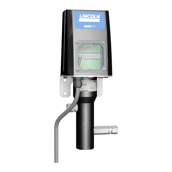
3. Overview, functional description 3. Overview, functional description Overview Fig. 1 1 Housing Includes the motor, the control pcb and the electrical connections of the EDL1. 2 Cover plate (pcb access) The transparent cover plate allows to imme- diately detect operating and fault status mes- sages by the LED on the control pcb. - Page 21 3. Overview, functional description Overview inlet and outlet fittings Fig. 2 4 Inlet fitting The pressurized lubricant (e.g. from a bar- rel pump) is fed to the EDL1 through an inlet fitting. 5 Outlet fitting The metered lubricant volume is fed to the lube point or to a metering device through the outlet fitting.
- Page 22 3. Overview, functional description Overview Fig. 3 6 Control pcb The control pcb serves to: ○ display operating states and fault messages ○ set parameters, e.g. pause time and out- put volume ○ trigger an additional lubrication by press- ing the key for additional lubrication (6.4) <...
- Page 23 3. Overview, functional description Overview Fig. 4 6.4 "Additional lubrication/ Reset" key Additional lubrication An additional lubrication cycle is triggered by pressing the key < 5 seconds. Reset An reset is triggered by pressing the key > 5 seconds. 6.5 Red LED (Fault signal terminal 8/9) Is lit when: ○...
-
Page 24: Technical Data
4. Technical data 4. Technical data 4.1 General technical data Admissible operating temperature -25 °C to 70 °C Operating pressure 280 bar max.* min. 2 bar Inlet pressure of lubrication greases max. 270 bar Inlet/ outlet fitting G 1/4“ Operating frequency maximum 1 cycle per minute Installation position any, but not rotating... -
Page 25: Electrics And Control Unit
4. Technical data 4.2 Electrics and control unit Operating voltage 24 V DC ± 10 % (reverse-polarity protected up to 32 V DC) Current input (standby) typ. 40 mA Current input (maximum) ≤ 4 A Power input (standby) typ. 1 W Power input (maximum) 96 W typ. -
Page 26: Functions Of The Dip Switches
4. Technical data 4.3 Functions of the DIP switches Setting of pause time DIP 1-4 Fig. 5 Setting of pause time DIP 7-8 Fig. 8 DIP switches 1-4 Serve to set the definite value for the pause. (Details see chapters 4.4, 4.5, 4.6) DIP switch 5 Serves to set the pause time to seconds or hours... -
Page 27: Setting Range For Pauses In Seconds
4. Technical data 4.4 Setting range for pauses in seconds 4.5 Setting range for pauses in hours 4.6 Setting range for pauses in pulses Setting of definite value in seconds Setting of definite value in hours Setting of definite value in pulses DIP switch DIP switch DIP switch... -
Page 28: Nominal Output Volume Per 24 Hours
4. Technical data 4.7 Nominal output volume per 24 hours DIP switch 6 DIP switch 6 Pause Pause in position in position time time seconds hours 1440 1234 1080 1000 1250 1600 951-171-010 - 28 - Version 06... -
Page 29: Assignment Of Connecting Terminals
4. Technical data Assignment of connecting terminals 4.10 Tightening torques Terminal Adhere to the following tightening torques when installing or repairing the pump. Power supply (+ 24 V DC) EDL1 to base plate, machine or control 10 Nm ± 1.0 Ready Mass (-) PE (protective earth) -
Page 30: Operating Modes Of The Edl1
4. Technical data 4.11 Operating modes of the EDL1 The EDL1 has 3 operating modes. These facilitate an adaptation to the different operating modes and controls. Application example: 4.12 ON/OFF mode Each time the power supply of the EDL1 is switched on, a lubrication cyle shall be performed. -
Page 31: Machine Contact Mode
4. Technical data Application example: 4.13 Machine contact mode The EDL1 shall carry out a lubrication cycle according to the pause time value (example If terminals 4 and 6 are bridged, = 4 hours) set via DIP switches 1-5. the EDL1 can be operated also Setting the machine contact mode, see autonomously without machine chapter 6.10. -
Page 32: Pulse Mode
4. Technical data 4.14 Pulse mode Application example: A sensor detects the number of arriving parts, chain links or train axles. After reaching the number of pulses (exam- ple = 4 pulses) preset via DIP switches 1-4, the EDL1 carries out a lubrication cycle. Setting the pulse mode, see chapter 6.14. -
Page 33: Type Identification Code
4. Technical data 4.15 Type identification code The type identification code facilitates identification of important equipment features of the product. New products can be configured and ordered by means of the type identification code. EDL1 - 100 - 01 - 01 + 924 Product designation EDL1 Corrosion protection / Position of line connections... -
Page 34: Delivery, Returns, And Storage
This particularly applies for parts made out of plastic and rubber (embrittlement) as well 5.3 Storage as for components primed with SKF products are subject to the following lubricant (ageing). storage conditions: ○ dry, dust- and vibration-free in closed premises ○... -
Page 35: Assembly
6. Assembly 6. Assembly 6.2 Place of installation 6.1 General information ○ Possibly existing visual monitoring de- Protect the product against humidity, dust Only qualified technical personnel may and vibrations and install it in an easily vices, e.g. pressure gauges, MIN/MAX install the products described in these accessible position to ensure all other in- markings, oil-level sight glasses or piston... -
Page 36: Minimum Assembly Dimensions
6. Assembly 6.3 Minimum assembly dimensions Minimum assembly dimensions Fig. 13 Ensure sufficient space for maintenance work or for a possible disassembly of the product by leaving a free space of at least 50 mm into each direction in addition to the stated dimensions. -
Page 37: Mechanical Connection
6. Assembly 6.4 Mechanical connection Connecting dimensions Fig. 14 The pump is fastened on the 4 mounting bores. Fastening is done by means of the screws 4 x M6 x 20C (hexagonal socket) in- cluded in the scope of delivery. Tightening torque = 10 Nm ±... -
Page 38: Electrical Connection
6. Assembly 6.5 Electrical connection Cover plate Fig. 15 Electrical connection of the EDL1 Fig. 16 Electrical connections must be done in such way that no forces are transferred to the connecting cables (tension-free connection). For electrical connection proceed as follows: •... -
Page 39: Configuration Of The Edl1
6. Assembly 6.6 Confi guration of the EDL1 The EDL1 has 3 operating modes. These facilitate an adaptation to the different operating conditions. 6.7 ON/OFF mode 6.9 Adjusting the output volume To set the ON/OFF mode proceed as follows: • Bring DIP switch 6 into position 1 or 0, Cover plate Fig. -
Page 40: To Set The Machine Contact Mode
6. Assembly Setting of definite value • Unscrew the screws (2.1) and keep them for future use. • Bring DIP switches 1-4 into the desired positions. • Remove the cover plate (2). • Reinstall the cover plate (2). ATTENTION Damage to the pcb is possible by slipping off with an inappropriate adjusting tool. -
Page 41: Pulse Mode
6. Assembly 6.14 Pulse mode • Bring DIP switch 6 into the desired • Bring DIP switches 1-4 into the desired position. positions. To set the mode proceed as follows: • Unscrew the screws (2.1) and keep them • Position 1 = approx. 1.0 ccm/ stroke •... -
Page 42: Initial Start-Up
7. Initial start-up 7. Initial start-up 7.1 General information 7.2 Triggering an additional lubrication Start-up is effected: Cover plate Fig. 23 cycle ○ by external signals like the machine con- tact or a controller provided by the owner To trigger an additional lubrication cycle proceed as follows: ○... -
Page 43: Inspections Prior To Initial Start-Up
7. Initial start-up In order to warrant safety and function, a person assigned by the operator must carry out the following inspections. Remedy detected de- fects before the initial start-up. Deficiencies may be remedied by an authorized and qualified specialist only. Start-up check list 7.3 Inspections prior to initial start-up Electrical connection carried out correctly. -
Page 44: Operation
8. Operation 8. Operation 8.1 Operation After its correct electrical and mechanical connection the EDL1 is ready for operation. Operation of the EDL1 follows the preset operating mode. 951-171-010 - 44 - Version 06... -
Page 45: Cleaning
Thoroughly remove residues of • Mark and secure wet areas. To do so, contact the SKF Customer Service. cleaning agents from the product • Keep unauthorized persons away. and rinse off with clear water. • Thorough cleaning of all outer surfaces with a damp cloth. -
Page 46: Maintenance
10. Maintenance Maintenance Regular and appropriate maintenance is a prerequisite to detect and clear faults in time. As it is not possible for us to exactly define the operating conditions, we cannot indicate any definite deadlines. The specific timelines have to be determined, verified at regular intervals and adapted, if necessary, by the operator based on the local operating conditions. -
Page 47: Troubleshooting
11. Faults Troubleshooting 11.1 Display of the operating states and fault conditions The operating states and fault conditions are displayed by different display patterns of the green, red and yellow LEDs on the control pcb. The following displays are possible. YELLOW GREEN Meaning/ possible cause... - Page 48 11. Faults Fault table Fault Possible cause Remedy If necessary, vent the lubrication system. To do so, observe Loosen inlet fitting. Visual check for bubbles in the lubricant the instructions of the upstream pump. Air pockets in the lubricant or Loosen outlet fitting.
-
Page 49: Repairs
12. Repairs Repairs WARNING Risk of injury Before carrying out any repair work, take at least the following safety measures: ○ Keep unauthorized persons away. ○ Mark and secure work area. ○ Depressurize the product. ○ Disconnect the product from the power supply and secure it against being switched on. -
Page 50: Replacement Of The Housing Cover
12. Repairs 12.1 Replacement of the housing cover • Reinstall the housing cover (1) by To replace the housing cover proceed as Spare parts of housing cover Fig. 26 screwing in the two screws (1.1). follows: • Implement the safety measures as speci- Tightening torque = 2 Nm ±... -
Page 51: Replacement Of The Control Pcb
12. Repairs 12.2 Replacement of the control pcb • Carefully loosen the white plug (6.7) of To replace the control pcb proceed as Fixations of the control pcb Fig. 29 the control pcb. follows: CLOSE • Implement the safety measures as speci- OPEN •... -
Page 52: Electrical Safety Test
12. Repairs • Testing the protective conductor system Risk of damage to the superior with regard to conductivity. machine. Fixations of the control pcb Fig. 32 Before installing the new control After the electrical safety test a pcb, check and, if necessary, correct functional test should be carried CLOSE OPEN... -
Page 53: Tests After Replacement Of The Power Supply Board
13. Shutdown and disposal 12.4.3 Electrical functionality test 12.4 Tests after replacement of the power 12.4.2 Electrical safety test supply board The electrical function test must be carried Use measuring equipment following out immediately after the repair following EN 61557 for the mentioned electrical tests. After replacement of the power supply the protection class of the electrical appara- ○... -
Page 54: Shutdown And Disposal
13. Shutdown and disposal Shutdown and disposal 13.1 Temporary shutdown 13.3 Disposal Dispose of or recycle electrical Temporarily shut the system down by: Disposal should be avoided or minimized ○ switching off the superior machine. wherever possible. Disposal of products con- components following WEEE taminated with lubricant must be effected vi directive 2012/19/EU. -
Page 55: Spare Parts And Accessories
14. Spare parts and accessories Spare parts and acces- sories The spare parts assemblies may be used exclusively for replacement of identical defective parts. Modifications with spare parts on existing products are not allowed. 14.1 Housing cover assy. Fig. 34 Designation Qty. -
Page 56: Hydraulic Fitting
14. Spare parts and accessories Fig. 36 14.3 Hydraulic fi tting Designation Qty. Part number Fitting GE 6-L G 1/4A CF (inlet/ outlet) 223-12477-8 Fitting GE 8-L G 1/4A CF (inlet/ outlet) 223-12477-6 Fitting GE 10-L G 1/4A CF (inlet/ outlet) 223-12272-9 14.4 Check valve Fig. -
Page 57: Pressure Switch
14. Spare parts and accessories 14.6 Pressure switch Fig. 39 Designation Qty. Part number Pressure switch 300 bar DSB1-S30000X-1A-01 Pressure switch 100 bar DSB1-S10000X-1A-01 Fig. 40 14.7 Connection cable for pressure switch Designation Qty. Part number Connection cable for pressure switch 664-85046-3 500 mm 14.8 Collecting sleeve assy. -
Page 58: Connection Diagrams
15. Connection diagrams Connection diagrams 15.1 Legend Cable colours following IEC60757 Abbreviation Colour Abbreviation Colour Abbreviation Colour Abbreviation Colour black green white pink brown yellow orange turquoise blue violet 951-171-010 - 58 - Version 06... -
Page 59: Connection Diagram For The On/Off Mode
15. Connection diagrams 15.2 Connection diagram for the ON/OFF mode Connection diagram Fig. 41 -EDL1 [ U ]: 24 VDC [ P ]: 30 W Ext. Sicherung Meldungen (über potentialfreie Kontakte = Relais): Ext.. Fuse 08/09 Störmeldung 1=Störung 0= keine Störung 24VDC L+ 10/11 Rückmeldung 1=Schmierzyklus ist erfolgreich beendet... -
Page 60: Connection Diagram For Machine Contact Mode
15. Connection diagrams 15.3 Connection diagram for machine contact mode Connection diagram Fig. 42 -EDL1 [ U ]: 24 VDC [ P ]: 30 W Ext. Sicherung Meldungen (über potentialfreie Kontakte = Relais): Ext.. Fuse 08/09 Störmeldung Sensor 1=Störung 0= keine Störung Schaltausgang 24VDC L+ 10/11 Rückmeldung... -
Page 61: Connection Diagram For Pulse Mode
15. Connection diagrams 15.4 Connection diagram for pulse mode Connection diagram Fig. 43 -EDL1 [ U ]: 24 VDC [ P ]: 30 W Ext. Sicherung Meldungen (über potentialfreie Kontakte = Relais): Ext.. Fuse 08/09 Störmeldung Sensor 1=Störung 0= keine Störung Impulsausgang 24VDC L+ 10/11 Rückmeldung... - Page 62 951-171-010-EN Not all lubricants are suitable for use in centralized lubrication systems. SKF does offer an inspec- tion service to test customer supplied lubricant to determine if it can be used in a centralized lubrica- 2017/01/26 tion system.
Need help?
Do you have a question about the LINCOLN EDL1 and is the answer not in the manual?
Questions and answers