Table of Contents
Advertisement
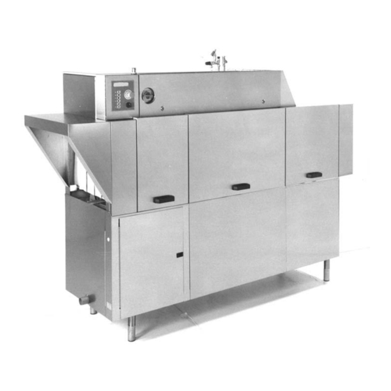
RACK CONVEYOR DISHWASHER
ELECTRICALLY HEATED
STEAM HEATED
TYPE: WD-211E ICS+, WD-241E ICS+ (400V)
Installation and operationmanual
S/N:
Valid from: 20030919
Rev.: 1.0
Advertisement
Table of Contents

Related Manuals for Metos WD-211E ICS+


Summary of Contents for Metos WD-211E ICS+
- Page 1 RACK CONVEYOR DISHWASHER ELECTRICALLY HEATED STEAM HEATED TYPE: WD-211E ICS+, WD-241E ICS+ (400V) Installation and operationmanual S/N: Valid from: 20030919 Rev.: 1.0...
- Page 3 Dear Customer, Congratulations on deciding to choose a Metos appliance for your kitchen activities. You made an excellent choice. We will do our best to make you a satisfied Metos customer like thousands of customers we have around the world.
- Page 5 19.9.2003 Rev. 1. General ......................1 1.1 Symbols used in the manual ..................1 1.2 Symbols used on the appliance ..................1 1.2.1 Machine marking ....................2 1.3 Checking the relationship of the appliance and the manual .......... 2 2. Safety ......................3 2.1 General ..........................
- Page 6 19.9.2003 Rev. 4. Installation ....................12 4.1 General ........................12 4.2 Demands on installation site ..................12 4.2.1 Lighting ........................ 12 4.2.2 Ventilation ......................12 4.2.3 Drain ........................12 4.2.4 Service space ......................12 4.3 Transport and storage ....................13 4.4 Unpacking ........................
- Page 7 19.9.2003 Rev. 1.0 General 1. General Carefully read the instructions in this manual as they contain important information re- garding proper, efficient and safe installation, use and maintenance of the appliance. Keep this manual in a safe place for eventual use by other operators of the appliance. 1.1 Symbols used in the manual This symbol informs about a situation where a safety risk might be at hand.
- Page 8 19.9.2003 Rev. 1.0 General 1.2.1 Machine marking The machine has two rating plates, of which one is placed at the bottom of one side. The other is placed in the switch cabinet. The technical information on the plates is also in- cluded in the wiring diagram.
- Page 9 19.9.2003 Rev. 1.0 Safety 2. Safety 2.1 General The machine is CE marked, which implies that the machine complies with the require- ments in the EU's machinery directive concerning product safety. Product safety implies that the machine is designed to prevent personal injury or damage to materials. Modification to the equipment without the approval of the manufacturer invalidates the manufacturer's product liability.
- Page 10 19.9.2003 Rev. 1.0 Safety 2.4 Detergent and rinse aid Only detergent and rinse aid which are ment for dishwashing machines are allowed. The wash goods must not be soaked or pre-washed with hand detergent. Contact your dish- washing detergent supplier for the choise of a suitable detergent and rinse aid. Protective gloves and goggles should be used when handling machine dishwashing deter- gent.
- Page 11 19.9.2003 Rev. 1.0 Safety 2.7.2 Cleaning floors When rinsing floors, water can splash up under the machine and damage the electrical components. These have not been designed to withstand rinsing with water. Do not spray the floor closer than 1 meter from the dishwasher. Special protecting covers are available for high pressure washers to prevent splash.
- Page 12 19.9.2003 Rev. 1.0 Directions for use 3. Directions for use 3.1 Preparations 3.1.1 Machine construction uppbyggnad Display Pushbutton for washtime / contact time Pushbutton for washtime / contact time Pushbutton for feeding Pushbutton for diagnostic- and functiontable Pushbutton for changing between texts Diode lamp Pushbutton to reset the alarm On / Off...
- Page 13 19.9.2003 Rev. 1.0 Directions for use 3.1.2 The application of the machine The machine is intended to be used for the washing of such items used for the preparation and serving of food, including various types of items for the storage of food. Washing shall therefore be carried out with machine dishwashing detergent intended for this pur- pose.
- Page 14 19.9.2003 Rev. 1.0 Directions for use 3.2 Use 3.2.1 Washing textpanel Selection of washtime / contact time START FEEDER will appear on the display. Select washtime 1 or 2 on the panel. Longer washtime for heavily soiled wash items. Shorter washtime for lightly and normally soiled wash items. Start the feeding by pressing the button (4).
- Page 15 19.9.2003 Rev. 1.0 Directions for use 3.2.3 Changing water For a good result it is important to change water often, allways if problem with foam in tanks. 3.3 After use - Cleaning HACCP is a preventive inspection system to ensure hygiene requirements during the washing process and cleaning of the machine.
- Page 16 19.9.2003 Rev. 1.0 Directions for use 3.3.2 Weekly cleaning (or as necessary) • Wash arms (12): Brush the interior. Also clean the wash arm nozzles. • Rinse nozzles (13) cleaning • Filter (17): The filter should be cleaned at least 2-3 times a week, or more frequent- ly, depending on the extent to which the machine is used.
- Page 17 19.9.2003 Rev. 1.0 Directions for use PROBLEM CAUSE ACTION Filling does not stop in tanks. Level pipe not in place. Fit level pipe. Level pipe rubber sleeve not sealing Check that level pipe is closed. to bottom plate. Change damaged rubber sleeve. Machine will not start washing.
- Page 18 19.9.2003 Rev. 1.0 Installation 4. Installation 4.1 General The machine must be installed by authorised personnel only. Read these instructions thoroughly as they contain important information that ensure cor- rect installation. The instructions should be used together with the machine's wiring diagram and flow di- agrams for water and steam.
- Page 19 19.9.2003 Rev. 1.0 Installation 4.3 Transport and storage Always transport the machine upright. Take care during transport, there is a risk of tipping. NB! The machine must not be transported without a pallet or other support. There must be some form of support beams used along the sides of the machine during all transport. The machine may otherwise be damaged.
- Page 20 19.9.2003 Rev. 1.0 Installation 4.6 Installation panel istall Machine installation (picture shows WD-241E) A = Drain connection. B = Perforat in end plate for drain connection. Display Pushbutton for washtime / contact time Pushbutton for washtime / contact time Pushbutton for feeding Pushbutton for diagnostic- and functiontable Pushbutton for changing between texts Diode lamp...
- Page 21 19.9.2003 Rev. 1.0 Installation 4.6.1 Location of machine Remove the protective plastic on the sides to be placed against the wall. Stand the dishwasher horizontally and adjust by means of its legs. Adjust the height of the machine with the legs. When the machine has been filled, make a new horizontelly test.
- Page 22 19.9.2003 Rev. 1.0 Installation 4.6.6 Ventilation The machine has a condenser connected to an exhaust fan to reduce the emission of steam. Exhaust air outlets for extracting steam can be placed above the antrance and exit open- ings as well as above the machine where steam is exhausted from condenser fan. 4.6.7 Installing extra equipment Limit switch Installation of limit switch will be done at the lower terminal block, which is placed in...
- Page 23 19.9.2003 Rev. 1.0 Installation 4.6.8 Setting the flows Cooling Condensing battery Reducing valve Y05 adjusts so the flow to cooling the condensing battery is 3,7 +0-0,2 l/ min. Final rinse Adjust the final rinse flow with the reducing valve Y02 which is placed in the solenoid- valve box (16).
- Page 24 19.9.2003 Rev. 1.0 Installation 4.7 Installing detergent and drying agent equipment diskmedel Hot water outlet. Alternative location of detergent equipment. Hole ø 25 mm for hose intended for solid detergent. Hole ø 19 mm for drying agent hose. Plugged connection ø 18 mm for connecting hose for solid detergent. Drying agent dosage outlet.
- Page 25 19.9.2003 Rev. 1.0 Installation 4.7.1 Electrical connection of equipment The machine is ready for fitting detergent and drying agent equipment but this is not in- cluded in the delivery. To avoid making unnecessary holes in the machine, the equipment can be placed on the wall behind the exit side of the machine.
- Page 26 19.9.2003 Rev. 1.0 Installation 4.7.2 Detergent dosage The water outlet (1) to detergent dosage is placed on incoming warm waterline. Hot water outlet Plugged holes for hoses...
- Page 27 19.9.2003 Rev. 1.0 Installation DETERGENT klister Adhesive label indicating alternative opening for detergent Measuring cell for detergent concentration...
- Page 28 19.9.2003 Rev. 1.0 Installation 4.7.3 Drying agent dosage The outlet for drying agent (6) is placed near the booster heaters. Outlet for drying agent dosage 4.8 Trial run Starting the machine and selecting programmes is described in the DIRECTIONS FOR USE.
- Page 29 19.9.2003 Rev. 1.0 Installation 4.8.2 Adjusting set values All the set values have been ready made on delivery. Changes can always be made to the machine's set values BUT ONLY BY SERVICE PERSONNEL. Instructions and tables for set values can be found in ADJUSTMENT INSTRUCTIONS. 4.8.3 Finishing the trial run •...
- Page 30 19.9.2003 Rev. 1.0 Installation...
- Page 31 19.9.2003 Rev. 1.0 Spare parts 5. Spare parts...
- Page 32 19.9.2003 Rev. 1.0 Spare parts...
- Page 33 19.9.2003 Rev. 1.0 Spare parts 5.1 Voltage codes Voltage code Voltage 3/N/PE∼400/230V 50Hz ∼250V 16A 50Hz 3/N/PE∼380/220V 50Hz 3/PE∼200V 50-60Hz 2/PE 220−240V 50Hz 3/N/PE∼415/240V 50Hz 3/PE∼230V 50Hz 3/PE∼220V 60Hz 3/PE∼380 50Hz 3/PE∼400V 50Hz 3/PE∼415V 50Hz 3/PE∼440V 60Hz 3/PE∼460V 60Hz 3/PE∼480V 60Hz 1/N/PE~220-240V 50Hz 2/PE~220-230V 60Hz 3/N/PE∼400/230V 50Hz...
- Page 34 19.9.2003 Rev. 1.0 Spare parts RL00ie...
- Page 35 Model sign Metos WD-241E Elektronic w43486,33 w43487,33 241I Model sign Rhima WD-241E Elektronic w43487,33 w44352,33 241I Model sign Shark WD-241E Elektronic w44352,33 w23959,31 Panel sign WD-151/331E ICS w23959,31 w38833,31 Panel sign Metos WD-151/331E ICS w38833,31 w45053,31 metos " Sign ""Metos ICS inside"" " w45053,31...
- Page 36 19.9.2003 Rev. 1.0 Spare parts 38792e...
- Page 37 19.9.2003 Rev. 1.0 Spare parts M-code Model Description W-code Water connections mm w37306,01 Valve hood w37306,01 5320206 Inlet device cw , Cpl w705,1004 5320205 Hot water connection , Cpl w705,1003 w705,1005 Output drying agent , Cpl w705,1005 5320200 Clamping sleeve w705,0405 5320198 Nut LK 63-15...
- Page 38 19.9.2003 Rev. 1.0 Spare parts 38796e...
- Page 39 19.9.2003 Rev. 1.0 Spare parts M-code Description W-code Electric cubicle 5315511 Pilot lamp socket w.bulb green , Cpl w618,0112 5315512 Lamp lens green 2066756 w618,1112 5320250 Lock with wheel , Cpl w792,0202 5320253 Locking knob w792,0205 w719,1031 O-ring 31.2x3.0 w719,1031 w43743,31 Attachement w43743,31...
- Page 40 19.9.2003 Rev. 1.0 Spare parts 38795e...
- Page 41 19.9.2003 Rev. 1.0 Spare parts M-code Description W-code Condensing battery, condensing fan 5320350 Condensing battery w810,0903 5315935 Fan VR92/2 220/380V 50Hz w738,2020 w36322,75 Lifting device , Cpl w36322,75 w36322,01 Cond.bat lifting WD-151-331E , Cpl w36322,01 5320175 Distance sleeve w43386,31 w700,1404 Locking nut LM DIN 985 M6 A2 w700,1404 w700,0123...
- Page 42 19.9.2003 Rev. 1.0 Spare parts 38801e...
- Page 43 19.9.2003 Rev. 1.0 Spare parts POS M-code Description W-code Doors, curtains w36457,75 Door locking , Cpl w36457,75 w36457,31 Door lock w36457,31 5320189 Stop lug w43517,31 5320184 Plate spring w43448,31 5320720 Screw RXS 4.2x13 A2 w700,0715 w700,0144 Screw M6S M8x70 A2 w700,0144 w700,1405 Locking nut LM M8 DIN 985 A2 w700,1405...
- Page 44 19.9.2003 Rev. 1.0 Spare parts 38847e...
- Page 45 19.9.2003 Rev. 1.0 Spare parts M-code Type Description W-code Feeding cradle 5320159 Ratchet , Cpl w43292,75 5320158 Ratchet w43292,31 w700,1822 Screw FRH M6x10 A2 w700,1822 5320706 Washer BRB 6.4x12.5 A2 w700,1204 5320152 Bushing w43285,31 5320095 211I Feeding cradle WD-211/211E , Cpl w23320,76 5320096 241I...
- Page 46 19.9.2003 Rev. 1.0 Spare parts 38835e...
- Page 47 19.9.2003 Rev. 1.0 Spare parts M-code Description W-code Feeding motor 5320132 Attachment overload w36112,01 breaker 5320051 Limit switch w60312803 5315207 Feed crank w31791,01 5315167 Protection washer w04877,31 5315121 Rubber packing w04297,31 5315111 Feed roller w04174,31 w806,1910 Feeding motor w806,1910 5320116 Attachment w36028,31 5315571...
- Page 48 19.9.2003 Rev. 1.0 Spare parts 38849e...
- Page 49 19.9.2003 Rev. 1.0 Spare parts M-code Type Description W-code Pre-wash 5315363 Photocell, receiver SPT1 w603,0001 5315365 Photocell, transmitter IED 12 w603,0012 5320337 Washer w41761,31 5320016 Hose clamp 50-70/12 w714,0111 5315654 Hose clamp 60-80/12 W3 w714,0112 5320233 Hose clamp w714,0122 5320235 Radiator hose ø50-1000mm w717,0150 5315686...
- Page 50 19.9.2003 Rev. 1.0 Spare parts 38854e...
- Page 51 19.9.2003 Rev. 1.0 Spare parts M-code Description W-code Chemical wash 5320344 Rinse arm, eccentric lock w23435,02 w792,0206 Eccentric lock w792,0206 w23847,75 Main pipe w23847,75 w36527,75 Lower rinsing ramp w36527,75 5320174 Adjustment plate w43361,01 5315199 Element 9kW 230/400V 17,6 ohm WD331E w30835,01 5320294 Pump 230/400V 50Hz , Cpl...
- Page 52 19.9.2003 Rev. 1.0 Spare parts 38858e...
- Page 53 19.9.2003 Rev. 1.0 Spare parts M-code Type Description W-code Final rinse, emptying device 5320192 Washer BRB 17x30 A2 w700,1211 5315208 Strainer, rec. final rinse w32440,01 5315204 Outlet sealing , Cpl w36019,75 5315699 Level pipe sealing w719,4036 w700,0905 Nut M6M M8 A2 w700,0905 w36039,01 Final rinse breaker...
- Page 54 19.9.2003 Rev. 1.0 Spare parts 38848e...
- Page 55 19.9.2003 Rev. 1.0 Spare parts M-code Description W-code Booster heater 1163,14 Booster heater 9kW 230/400V (E) , Cpl Electric w01163,14 w01163,16 Booster heater 12kW 230/400V , Cpl Electric w01163,16 5320267 Container booster heater (E) , Cpl Electric w01162,04 w44203,31 Attachment temp.sensor Electric w44203,31 w700,1603 Locking nut LM DIN985 M4 A2...
- Page 56 19.9.2003 Rev. 1.0 Spare parts 38853e...
- Page 57 19.9.2003 Rev. 1.0 Spare parts M-code Description W-code Couplings, pipe details 5320204 Coupling straigth 15x15 MF , Cpl w705,0914 5315581 Coupling straight 15x15 MF cr , Cpl Electric w705,0912 w705,1008 Coupl.straight 15xR15 int. tread cr , Cpl w705,1008 5315583 " Coupling angeled "" x 15 MF cr , Cpl " w705,1607 w705,1903 Coupling ang.15xR15 int.thread cr , Cpl...
- Page 58 19.9.2003 Rev. 1.0 Spare parts 38871e...
- Page 59 19.9.2003 Rev. 1.0 Spare parts POS M-code Description W-code Pre-rinse zone FS-40, Optional equipment w43541,31 Pipe tank-washpipe upper FS-40 w43541,31 w792,0206 Eccentric lock w792,0206 5320221 Bracket for washarm FS-40 w43917,01 w43511,76 Pipe joint wash arm FS-40 w43511,76 w36279,02 Connection pipe wash arm FS-40 w36279,02 w43511,75 Pipe joint wash arm FS-40...
- Page 60 19.9.2003 Rev. 1.0 Spare parts 38870e...
- Page 61 19.9.2003 Rev. 1.0 Spare parts M-code Description W-code Drying zone Upper part, Optional equipment w32655,01 Seperation plate w32655,01 5320250 Lock with wheel , Cpl w792,0202 5320253 Locking knob w792,0205 w738,2022 Fan VR 184/2 w738,2022 w38302,75 Motor hood w38302,75 w36211,31 Door electric cubicle w36211,31 w23447,31 Electric cubicle T-60,90...
- Page 62 19.9.2003 Rev. 1.0 Spare parts 38872e...
- Page 63 19.9.2003 Rev. 1.0 Spare parts M-code Model Description W-code Drying zone Lower part, Optional equipment 5320092 T-60 Door 600mm , Cpl Drying zone T-60 w23314,75 5320093 T-90 Door 900mm , Cpl Drying zone T-90 w23315,75 5320237 Handle PECO P225/132 M8 w718,0842 w43534,31 Attachment magnet...
- Page 64 19.9.2003 Rev. 1.0 Spare parts...
- Page 65 19.9.2003 Rev. 1.0 Technical specifications 6. Technical specifications Flow chart [211]........Flow chart FS-40 [211,241,331]... Flow chart Demiwater [211]....Flow chart [241]........Flow chart Demiwater [241]....Flow chart Steam [151,211,241,331] ... E53856 R11 ........... E53857 R11 ........... E53858 R11 ........... E53859 R11 ...........
- Page 66 19.9.2003 Rev. 1.0 Technical specifications E53866 R11 ........... E53905 R16 ........... E53906 R17 ........... E54655 R2 ..........E54656 R2 ..........E54862 R1 ..........E54863 R1 ..........E54864 R1 ..........E54865 R1 ..........E54866 R1 ..........E54867 R1 ..........E54868 R1 ..........E54869 R1 ..........
- Page 67 Flow chart [211]...
- Page 68 Flow chart FS-40 [211,241,331]...
- Page 69 Flow chart Demiwater [211]...
- Page 70 Flow chart [241]...
- Page 71 Flow chart Demiwater [241]...
- Page 72 Flow chart Steam [151,211,241,331]...
- Page 73 E53856 R11...
- Page 74 E53857 R11...
- Page 75 E53858 R11...
- Page 76 E53859 R11...
- Page 77 E53860 R11...
- Page 78 E53861 R11...
- Page 79 E53862 R11...
- Page 80 E53863 R11...
- Page 81 E53864 R11...
- Page 82 E53865 R11...
- Page 83 19.9.2003 Rev. 1.0 Technical specifications E53866 R11 W-KOD M-KOD DESCRIPTION w61001765 5315258 Computerboard WD-T 150/330 w61007950 E-prom WD151E/331E symbol w61007960 E-prom WD151E/331E text w61007970 E-prom M151E/331E symbol w61008000 E-prom M151E/331E text w61008030 E-prom M151E/331E ICS+ symbol w61008010 5320340 E-prom M151E/331E ICS+ text w61008020 E-prom M151E/331E ICS+ text french A2:1...
- Page 84 19.9.2003 Rev. 1.0 Technical specifications W-KOD M-KOD DESCRIPTION w61026893 5320062 Connection sleeve UMNL TE AMP w61001355 5320055 Connection 8-pole male w61026893 5320062 Connection sleeve UMNL TE AMP w61001355 5320055 Connection 8-pole male w61026893 5320062 Connection sleeve UMNL TE AMP w61001355 5320055 Connection 8-pole male w63722113...
- Page 85 19.9.2003 Rev. 1.0 Technical specifications W-KOD M-KOD DESCRIPTION QM15 w63113023 5320069 Prot.motor SW CTI25 0.40-0.63A w63713042 5320073 Auxiliary contact block QM16 w63113024 5320070 Prot.motor sw cti25 0.63-1.00A w63713042 5320073 Auxiliary contact block QM162 w63113025 Prot.motor cti25. 1.00-1.60A w63713042 5320073 Auxiliary contact block w63113027 5320072 Prot.motor sw CTI25 2 50-4 00A...
- Page 86 19.9.2003 Rev. 1.0 Technical specifications W-KOD M-KOD DESCRIPTION w709,1903 5315612 Water meter EVW-20 pulse sensor w30835,02 5315201 Element 12kW 230/400V E31:1 w604,2000 5315389 Airelement 2kW 230V E31:2 w604,2000 5315389 Airelement 2kW 230V E31:3 w604,2000 5315389 Airelement 2kW 230V w30835,02 5315201 Element 12kW 230/400V w30835,02 5315201...
- Page 88 E53905 R16...
- Page 89 19.9.2003 Rev. 1.0 Technical specifications E53906 R17 W-KOD M-KOD DESCRIPTION w63722113 5320074 Contactor CI9 24V/50-60Hz w637,3111 5320287 Auxiliary contact block 3-4 K17-1 w63722113 5320074 Contactor CI9 24V/50-60Hz K172 w63722113 5320074 Contactor CI9 24V/50-60Hz K173 w63722113 5320074 Contactor CI9 24V/50-60Hz w63722113 5320074 Contactor CI9 24V/50-60Hz w63722113...
- Page 90 E54655 R2...
- Page 91 19.9.2003 Rev. 1.0 Technical specifications E54656 R2 W-KOD M-KOD DESCRIPTION K102 w63722113 5320074 Contactor CI9 24V/50-60Hz w61426155 Relay socket w61426135 5315499 Time relay w61426155 Relay socket QM102 w63113027 5320072 Prot.motor sw CTI25 2 50-4 00A w63713042 5320073 Auxiliary contact block w62210302 Connector w637,3111...
- Page 92 E54862 R1...
- Page 93 E54863 R1...
- Page 94 E54864 R1...
- Page 95 E54865 R1...
- Page 96 E54866 R1...
- Page 97 E54867 R1...
- Page 98 E54868 R1...
- Page 99 E54869 R1...
- Page 100 E54870 R1...
- Page 101 E54871 R1...
- Page 102 19.9.2003 Rev. 1.0 Technical specifications E54872 R1 W-KOD M-KOD DESCRIPTION w61001765 5315258 Computerboard WD-T 150/330 w61007950 E-prom WD151E/331E symbol w61007960 E-prom WD151E/331E text w61007970 E-prom M151E/331E symbol w61008000 E-prom M151E/331E text w61008030 E-prom M151E/331E ICS+ symbol w61008010 5320340 E-prom M151E/331E ICS+ text w61008020 E-prom M151E/331E ICS+ text french A2:1...
- Page 103 19.9.2003 Rev. 1.0 Technical specifications W-KOD M-KOD DESCRIPTION w61026893 5320062 Connection sleeve UMNL TE AMP w61001355 5320055 Connection 8-pole male w63722113 5320074 Contactor CI9 24V/50-60Hz w63722113 5320074 Contactor CI9 24V/50-60Hz w63722113 5320074 Contactor CI9 24V/50-60Hz w63722113 5320074 Contactor CI9 24V/50-60Hz w63722113 5320074 Contactor CI9 24V/50-60Hz...
- Page 104 19.9.2003 Rev. 1.0 Technical specifications W-KOD M-KOD DESCRIPTION w60102201 5315246 Switch man w601,0200 5315331 Change over switch w60681063 5320086 Trafo 210-420/25.5/18/10.5V wACS121805 Rectifier w61075646 Ferrit core Toroid w52920873 5320044 Clamp earth w62279681 Conn block w62270531 Conn.bloc SP02 w733,0103 5315791 Pressure switch 111008 210/142 w733,0103 5315791 Pressure switch 111008 210/142...
- Page 105 19.9.2003 Rev. 1.0 Technical specifications W-KOD M-KOD DESCRIPTION w805,2570 5320294 Pump 230/400V 50Hz w716,0602 5320041 Measuring device of detergent w60383733 5315377 Limit switch 83.733AE w60312803 5320051 Limit switch w729,2401 5320248 Solenoid valve housing ev220a w729,2403 5320249 Solenoid ev220a 24v/50-60hz w729,2401 5320248 Solenoid valve housing ev220a w729,2403...
- Page 106 19.9.2003 Rev. 1.0 Technical specifications Item Type Specification General data Max.surface temp. at room temp. +20°C 35 ºC Sound level (1m from machine) 68 dB Condensing batterys cooling surface, m² 25 m²/h Condensation fan. Capacity m³/h 200 m³/h Ventilation requirements m³/h 1200 m³/h Capacity, baskets/hour (adjustable) 211I...
- Page 107 D-080 9810 EC conformancy certificate Manufacturer Hereby certifies that: Dishwasher WD-XXXE ICS+ Type: 0000 Serial Number:...
Need help?
Do you have a question about the WD-211E ICS+ and is the answer not in the manual?
Questions and answers