
Related Manuals for Metos WD-B 500-900


Summary of Contents for Metos WD-B 500-900
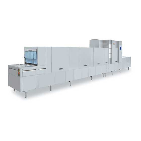
- Page 1 FLIGHT-TYPE DISHWASHER WD-B 500-900 Installation and user manual S/N: Valid from: 01. 01. 2011 Rev.: 3.0...
- Page 2 When you need service or technical help, please let us know the serial number shown on the rating plate. This will make it easier to provide you with correct serv- ice. For your convenience, space is provided below for you to record your local Metos service contact information. METOS TEAM Metos service phone number:................
-
Page 3: Table Of Contents
WD-B 500 - WD-B 900 Rev. 1. General information ................. 1 1.1 Symbols used in this manual ................1 1.2 Symbols on the dishwasher ................1 1.2.1 Machine marking ..................2 1.3 RoHS compatible ..................... 2 1.4 Checking that the machine and the manual correspond ........2 2. - Page 4 WD-B 500 - WD-B 900 Rev. 3.7 Connections ....................16 3.7.1 Water connection ..................17 3.7.2 Steam connection (extra equipment) ............17 3.7.3 Condensation water connection (extra equipment) ........ 17 3.7.4 Drain connection ..................18 3.7.5 Detergent and drying agent ..............18 3.7.6 Ventilation ....................
-
Page 5: General Information
WD-B 500 - WD-B 900 Rev. 3.0 General information 1. General information Read the instructions in this manual carefully as they contain important informa- tion regarding the correct, effective and safe installation, use and servicing of the dishwasher. Keep this manual in a safe place so that it can be used by other operators of the dishwasher. -
Page 6: Machine Marking
WD-B 500 - WD-B 900 Rev. 3.0 General information 1.2.1 Machine marking The rating plates are located at the bottom of the outfeed side and in the electrical cabinet. The technical information on the plates is also included on the machine's wiring diagram. -
Page 7: Safety Instructions
WD-B 500 - WD-B 900 Rev. 3.0 Safety instructions 2. Safety instructions 2.1 General information The machine is CE marked, which means that it complies with the requirements of the EU machinery directive with regard to product safety. Product safety means that the design of the machine will prevent personal injury or damage to property. -
Page 8: Detergent And Drying Agent
WD-B 500 - WD-B 900 Rev. 3.0 Safety instructions 2.4 Detergent and drying agent Only detergent and drying agent intended for industrial dishwashing machines must be used. Ordinary washing-up liquid must not be used in the machine or for soaking. Contact your detergent supplier regarding the choice of a suitable deter- gent. -
Page 9: Cleaning
WD-B 500 - WD-B 900 Rev. 3.0 Safety instructions 2.7 Cleaning The water in the chemical wash tank is at a temperature of approx. 60°C and con- tains detergent. Be careful when emptying and cleaning the tanks. Use protective gloves. 2.7.1 Pressure washing The machine must not be cleaned with a pressure washer, either inside or out. -
Page 10: Installation
WD-B 500 - WD-B 900 Rev. 3.0 Installation 3. Installation 3.1 General information The machine must be installed by authorised personnel only. Read these instructions carefully, as they contain important information regarding the correct installation method. The instructions should be used together with the machine drawing, wiring dia- gram and flow diagram. -
Page 11: Space For Servicing
WD-B 500 - WD-B 900 Rev. 3.0 Installation 3.2.4 Space for servicing The area above the machine must not contain any equipment which could pre- vent the fitting, servicing and replacement of parts. A free height of at least 2.8 metres is required in order to remove the inspection doors. -
Page 12: Marking Of Sections
WD-B 500 - WD-B 900 Rev. 3.0 Installation 3.4 Marking of sections The machine is normally divided into two sections. In some cases the machine can be delivered in more than two sections. The installation instructions describe the assembly of a machine that has been split into two sections. Regardless of the number of sections, the assembly of all sections is undertaken in the same way. -
Page 13: Unpacking
WD-B 500 - WD-B 900 Rev. 3.0 Installation 3.5 Unpacking • Check against the delivery note that all the units have been delivered. • Remove the packaging, but leave the pallet and any transport supports in place. • Inspect the machine for any transport damage. •... -
Page 14: Installation
WD-B 500 - WD-B 900 Rev. 3.0 Installation 3.6 Installation 3.6.1 General information Parts which must be assembled are prepacked inside each machine section to- gether with the necessary bolts, nuts, etc. Remove all lower cover plates (5). The final position of the machine is either free-standing in the room or placed with the back against a wall. -
Page 15: Assembly Of Sections
WD-B 500 - WD-B 900 Rev. 3.0 Installation 3.6.2 Assembly of sections • Remove any transport supports. • Place section 2 in the appropriate place at the right height. Check that the section is horizontal using a spirit level. Adjust the machine using the legs. •... - Page 16 WD-B 500 - WD-B 900 Rev. 3.0 Installation Silikon Application of silicon. A=Bolt hole B=Silicon Skarv Locking the stand. A=Leg B=Joint on the stand C=Stand D=M6x10 Bolts E=Joining tube...
-
Page 17: Pipes
WD-B 500 - WD-B 900 Rev. 3.0 Installation Assembly of clamp strips and upper cover plates • When the sections have been fitted together, the clamp strips (A) should be fitted inside the joint. Fit the upper clamp strip first. Apply a small amount of silicon to the strips before fitting them into place. -
Page 18: Assembling The Track And Conveyor Belt
WD-B 500 - WD-B 900 Rev. 3.0 Installation 3.6.4 Assembling the track and conveyor belt Screw the upper and lower tracks (3, 7) of the conveyor belt together at the join between the sections using the support plates and nuts supplied. Bana Locking the upper and lower tracks. -
Page 19: Other Assembly
WD-B 500 - WD-B 900 Rev. 3.0 Installation 3.6.5 Other assembly • Fit the chain (4) to the drive motor. • Pull out and connect the electric cables for the pumps and other compo- nents. The cables are located at the section joint. •... -
Page 20: Connections
WD-B 500 - WD-B 900 Rev. 3.0 Installation 3.7 Connections The picture below shows a machine with the feed direction from right to left. The length of the infeed and outfeed and the number of washing and drying zones vary depending on the size of the machine. The machine can also operate in the opposite direction. -
Page 21: Water Connection
WD-B 500 - WD-B 900 Rev. 3.0 Installation 3.7.1 Water connection The machine is supplied as standard without stopcocks for the water supply. Stopcocks must be installed on incoming pipes. It is important that the water supply has sufficient pressure to ensure the correct flow of water to the machine. -
Page 22: Drain Connection
WD-B 500 - WD-B 900 Rev. 3.0 Installation 3.7.4 Drain connection The drain is connected using a 50mm metal tube which tolerates mechanical im- pacts. The drain must run to a floor drain, where its opening must be above the water level. -
Page 23: Electrical Connection
WD-B 500 - WD-B 900 Rev. 3.0 Installation 3.7.7 Electrical connection This symbol on a machine component warns of the presence of electrical equip- ment. The component may only be removed by a qualified electrician. The ma- chine is sensitive to electrostatic discharge (ESD), and a static electricity bracelet must therefore be used when handling the electronics. - Page 24 WD-B 500 - WD-B 900 Rev. 3.0 Installation An earth cable for potential equalisation is connected to the earth bolt (B) on the stand. The connection is located on the beam in front of the heat exchanger (A). Jordbult Position of the earth bolt. A=Heat exchanger B=Earth bolt After completing the electrical installation, switch on the main switch and all circuit...
-
Page 25: Checking And Setting The Final Rinse Flow
WD-B 500 - WD-B 900 Rev. 3.0 Installation 3.8 Checking and setting the final rinse flow WDB_09 Control panel functions for checking the final rinse flow Button for the feed Button for the diagnostics function Button for switching between diagnostic messages Display for showing texts The final rinse flow is set in the factory, but should be checked after the machine has been installed. -
Page 26: Filling Booster Heater 3 With R/O Water (Additional Equipment)
WD-B 500 - WD-B 900 Rev. 3.0 Installation 3.9 Filling booster heater 3 with R/O water (additional equipment) WDB_15 Functions on the control panel and circuit board for activating and using the diag- nostics function Button for activating the diagnostics function. Button for switching between diagnostic messages. -
Page 27: Adjusting The Air Flow In The Drying Zone
WD-B 500 - WD-B 900 Rev. 3.0 Installation 3.10 Adjusting the air flow in the drying zone The positioning of the spread plates, guide plates etc. which control the air flow will depend on a variety of factors, such as the size of the machine, whether it is electrically or steam heated, the temperature and ventilation in the dishwashing room etc. -
Page 28: Wd-B 500, Electrically Heated, One Drying Zone (Drying Zone Only In Green Variant)
WD-B 500 - WD-B 900 Rev. 3.0 Installation 3.10.1 WD-B 500, electrically heated, one drying zone (drying zone only in GREEN variant) • Damper (I) half open. • Damper plate (B) fully open towards final rinse zone. • Spreader plate (E) pushed towards infeed. 2 mm gap between (E) and (D). •... -
Page 29: Trial Run
WD-B 500 - WD-B 900 Rev. 3.0 Installation 3.11 Trial run If a start-up report has been supplied with the machine, this should be used for the trial run and testing. 3.11.1 Checks during trial run If there is a start-up report, follow the instructions in the report and carry out the checks described. -
Page 30: Concluding The Trial Run
WD-B 500 - WD-B 900 Rev. 3.0 Installation 3.11.2 Concluding the trial run • Empty the machine if it is not being used after the trial run has been con- cluded. Clean the inside of the machine if dirty dishware has been used for the trial run. -
Page 31: Cleaning The Exterior
WD-B 500 - WD-B 900 Rev. 3.0 Installation 3.12 Cleaning the exterior Remove the protective plastic from the machine and polish it with a suitable clean- ing material for stainless steel plate. Use a suitable solvent to remove any residual adhesive from the plastic. Rub with a forwards and backwards movement in the polishing direction of the plate. -
Page 32: Instructions For Use
WD-B 500 - WD-B 900 Rev. 3.0 Instructions for use 4. Instructions for use All staff using the machine must be given training in how the machine works by the person responsible for staff safety. The dishwasher should not be used by anyone suffering from a physical or mental illness. - Page 33 WD-B 500 - WD-B 900 Rev. 3.0 Instructions for use 15 16 WDB_11 The picture shows a machine with pre-wash, intermediate rinse (extra equipment) and two chemical wash tanks. The machines can be supplied with more or fewer washing zones and the reverse feed direction. Display Symbol for contact time (washing time) Symbol for washing...
-
Page 34: Preparations Before Filling
WD-B 500 - WD-B 900 Rev. 3.0 Instructions for use 4.1.2 Preparations before filling Check: • that the machine has been cleaned and that the stopcocks for the water are open. • the amount of detergent and drying agent. NOTE: Ordinary washing-up liquid must not be used in the machine or for soak- ing. -
Page 35: Using The Machine
WD-B 500 - WD-B 900 Rev. 3.0 Instructions for use 4.2 Using the machine 4.2.1 Washing Setting for normal or heavily soiled loads (Extra equipment) As additional equipment, the machine can be fitted with a function for washing normal or heavily soiled loads. If there is an option to change the rinse pressure, the machine is fitted with a lever (22) next to the infeed. -
Page 36: Emergency Stop
WD-B 500 - WD-B 900 Rev. 3.0 Instructions for use Selecting the contact time/wash time When the machine's feed has started, a text message appears on the display in- dicating that the machine is ready to wash and giving a contact time in seconds. The contact time is the same as the wash time. -
Page 37: Lights Which Indicate Alarms (Extra Equipment)
WD-B 500 - WD-B 900 Rev. 3.0 Instructions for use 4.2.3 Lights which indicate alarms (extra equipment) The light bar (17) has flashing or non-flashing lights to indicate the following states: • Green non-flashing light = Machine in operation • Yellow flashing light = Alarm. -
Page 38: After Use
WD-B 500 - WD-B 900 Rev. 3.0 Instructions for use 4.3 After use 4.3.1 End of wash, cleaning HACCP is a preventive inspection system which ensures that hygiene require- ments are met during the washing process and the cleaning of the machine. As a result of its design, the machine meets strict hygiene requirements. - Page 39 WD-B 500 - WD-B 900 Rev. 3.0 Instructions for use Cleaning the exterior Wipe the outside of the machine with a soft, damp cloth. If detergent is used, it must not contain abrasives. Detergents containing abra- sives will damage the stainless steel panels. The outside of the machine must not be hosed down.
-
Page 40: Cleaning And Checking Each Week Or As Required
WD-B 500 - WD-B 900 Rev. 3.0 Instructions for use 4.3.3 Cleaning and checking each week or as required Weekly cleaning should be more thorough than daily cleaning. In addition to the daily cleaning measures, follow these instructions: • Clean the washer arms (19). Remove the lower washer arms by pushing the lock on the front of the washer arm down and pulling the washer arm out. - Page 41 WD-B 500 - WD-B 900 Rev. 3.0 Instructions for use Alarm texts Alarm text Cause Action (14) WEAK SIGNAL FROM There is dirt on one of the two Clean the photocells. The PHOTOCELL START WASH photocells (30) inside the infeed alarm in the display will disap- - CLEAN PHOTOCELL hood.
- Page 42 WD-B 500 - WD-B 900 Rev. 3.0 Instructions for use Alarm texts Alarm text Cause Action (44) LOW LEVEL IN TANK 4 The outlet seal is not closed. The Close the outlet seal. Check (CHEM WASH TANK 3) outlet seal's rubber sleeve is not the rubber sleeve.
-
Page 43: Troubleshooting
WD-B 500 - WD-B 900 Rev. 3.0 Instructions for use Troubleshooting In addition to the faults shown on the control panel, other faults can occur. The table below shows some faults which can be rectified by the operator. If the prob- lem persists, contact authorised service personnel. - Page 44 WD-B 500 - WD-B 900 Rev. 3.0 Instructions for use Troubleshooting Problem Cause Action The dishware tips over. The dishware is too light. Put the dishware in baskets. Use a grid to hold the items in place. Rinsing pressure is too Check that the lever (22) is high.
-
Page 45: Technical Information
WD-B 500 - WD-B 900 Rev. 3.0 Technical information 5. Technical information The flight-type dishwasher WD-B comes in several standard sizes with different infeed and outfeed lengths. The machine also comes in special versions in which the length, width, height, connection positions and other features differ from the standard models.
Need help?
Do you have a question about the WD-B 500-900 and is the answer not in the manual?
Questions and answers