
Related Manuals for Metos WD-11


Summary of Contents for Metos WD-11
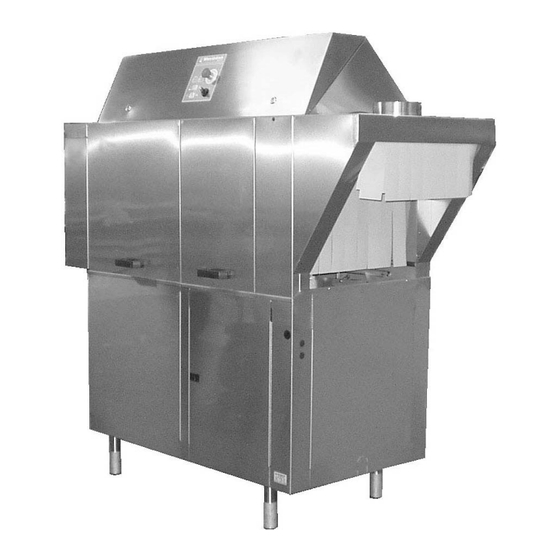
- Page 1 RACK CONVEYOR DISHWASHER Electrically heated machine Steam heated machine TYPE: WD-11 Installation and operationmanual S/N: Valid from: 04. 07. 2005 Rev.: 1.3...
- Page 3 Dear Customer, Congratulations on deciding to choose a Metos appliance for your kitchen activities. You made an excellent choice. We will do our best to make you a satisfied Metos customer like thousands of customers we have around the world.
-
Page 5: Table Of Contents
4.7.2005 Rev. 1. General ......................1 1.1 Symbols used in the manual ..................1 1.2 Symbols used on the appliance ..................1 1.2.1 Machine marking ....................1 1.3 Checking the relationship of the appliance and the manual .......... 2 2. Safety ......................3 2.1 General .......................... - Page 6 4.7.2005 Rev. 3.8 Trial run (f.o.m 20050223) ..................14 3.8.1 Start-up schedule ....................15 3.9 Technical documentation ..................... 16 4. Directions for use ..................17 4.1 Preparations ......................... 17 4.1.1 Machine construction ................... 17 4.1.2 The application of the machine ................18 4.1.3 Preparations before filling ...................
-
Page 7: General
4.7.2005 Rev. 1.3 General 1. General Carefully read the instructions in this manual as they contain important information re- garding proper, efficient and safe installation, use and maintenance of the appliance. Keep this manual in a safe place for eventual use by other operators of the appliance. 1.1 Symbols used in the manual This symbol informs about a situation where a safety risk might be at hand. -
Page 8: Checking The Relationship Of The Appliance And The Manual
4.7.2005 Rev. 1.3 General Machine type Machine number Year of manufacture Enclosure class Volatge Number of phases with or without zero Frequency Main fuse Motor output Electrical heating output Max. power 1.3 Checking the relationship of the appliance and the manual The rating plate of the appliance indicates the serial number of the appliance. -
Page 9: Safety
4.7.2005 Rev. 1.3 Safety 2. Safety 2.1 General The machine is CE marked, which implies that the machine complies with the require- ments in the EU's machinery directive concerning product safety. Product safety implies that the machine is designed to prevent personal injury or damage to materials. Modification to the equipment without the approval of the manufacturer invalidates the manufacturer's product liability. -
Page 10: Operation
4.7.2005 Rev. 1.3 Safety Only detergent and rinse aid which are ment for dishwashing machines are allowed. The wash goods must not be soaked or pre-washed with hand detergent. Contact your dish- washing detergent supplier for the choise of a suitable detergent and rinse aid. Protective gloves and goggles should be used when handling machine dishwashing deter- gent. -
Page 11: Disposal Of The Appliance
4.7.2005 Rev. 1.3 Safety for high pressure washers to prevent splash. NOTE! Splashing from underneath can also arise when using ordinary water hoses. 2.8 Disposal of the appliance The disposal of the appliance when its economical lifetime has been reached must be car- ried out in accordance with local rules and regulations. -
Page 12: Installation
4.7.2005 Rev. 1.3 Installation 3. Installation 3.1 General The machine must be installed by authorised personnel only. Read these instructions thoroughly as they contain important information that ensure cor- rect installation. The instructions should be used together with the machine's wiring diagram and flow di- agrams for water and steam. -
Page 13: Transport And Storage
4.7.2005 Rev. 1.3 Installation 3.3 Transport and storage Always transport the machine upright. Take care during transport as there is a risk of tipping. NB! The machine must not be transported without a pallet or other support. There must be some form of support beams used along the sides of the machine during all transport. The machine may otherwise be damaged. - Page 14 4.7.2005 Rev. 1.3 Installation WD11 01 A = Alternative electrical connection from floor (behind front cover plate). B = Perforat in end plate for drain connection. Ventilation connection outfeed ø160 mm, 1200m³/h. Hot-water connection 55-70°C R½" (backside) Electrical box Electrical connection (backside) Photocell Steam connection R¾"...
-
Page 15: Location Of Machine
4.7.2005 Rev. 1.3 Installation 3.6.1 Location of machine Remove the protective plastic on the sides to be placed against the wall. Put in place the machine and check with a spirit level that it is horizontal. Place the spirit level on the join between the machine tank and the upper part. Adjust the height of the machine with the legs. -
Page 16: Limit Switch
4.7.2005 Rev. 1.3 Installation Limit switch Installation of limit switch will be done at block X10 in the electrical cabinet. Take away the existing clamp. See machines electrical connection. The limit switch is signified S11. NOTE! The machine has a power on 24V. Conveyors Installation of in- and out equipments (conveyors, curves) will be done after the electric connection diagram. -
Page 17: Electrical Connection Of Equipment
4.7.2005 Rev. 1.3 Installation WD121Ediskmedel Hot water outlet. Alternative location of detergent equipment. Hole ø 25 mm for hose intended for solid detergent. Hole ø 19 mm for drying agent hose. Plugged connection ø 18 mm for connecting hose for solid detergent. Drying agent dosage outlet. -
Page 18: Detergent Dosage
4.7.2005 Rev. 1.3 Installation To avoid making unnecessary holes in the machine, the equipment can be placed on the wall behind the exit side of the machine. Terminal blocks for detergent and drying agent. 3.7.2 Detergent dosage The water outlet (1) to detergent dosage is placed on incoming warm waterline. Hot water outlet... - Page 19 4.7.2005 Rev. 1.3 Installation Plugged holes for hoses DETERGENT klister Adhesive label indicating alternative opening for detergent...
-
Page 20: Drying Agent Dosage
4.7.2005 Rev. 1.3 Installation Measuring cell for detergent concentration 3.7.3 Drying agent dosage The outlet for drying agent (6) is placed near the booster heaters. Outlet for drying agent dosage 3.8 Trial run (f.o.m 20050223) Read the INSTRUCTIONS FOR USE before preparing the machine for the trial run. They contain a description of the actions to be taken to prepare the machine for operation. -
Page 21: Start-Up Schedule
4.7.2005 Rev. 1.3 Installation 3.8.1 Start-up schedule Machine type: Machine number: Installation date: Customer: Dealer: Postal address: Contact person: Telephone: Telephone: Contact person: Installatio company: Service company: Contact person: Telephone: Telephone: Detergent supplier: Signature of customer: Read the contents of the Installation and user manuals carefully. Then check off as fol- lows: 1. -
Page 22: Technical Documentation
4.7.2005 Rev. 1.3 Installation • There are no water leaks • The doors breaker functions • The limit switch functions • Release of steam from the machine • The water temperatures are maintained • The washed items are clean • The washed items dry off Note: The equipment for detergent and drying agent is roughly set at the factory;... -
Page 23: Directions For Use
4.7.2005 Rev. 1.3 Directions for use 4. Directions for use 4.1 Preparations 4.1.1 Machine construction 16 14 15 panel 5 6 7 WD11uppbyggnad WD121Esk1 Temperature display chemical wash Pushbutton for automatic operation Door symbol Diode lamp Feed overload symbol or emergency stop depressed Pushbutton for manual operation Feed overload symbol, feed motor, in and out feed conveyors and activated limit switch... -
Page 24: The Application Of The Machine
4.7.2005 Rev. 1.3 Directions for use Symbol for final rinse. The symbol flashes if the final rinse strainer is blocked Emergency stop Temperature display, final rinse Curtains Door Rinse nozzles Catch Wash arms Strainer plate Strainers Level pipe Level pipe seal Outlet sealing Strainer for the final rinse 4.1.2 The application of the machine... -
Page 25: Utensil Positions In Basket
4.7.2005 Rev. 1.3 Directions for use • Press the AUT button. The machine starts and operates a few seconds to mix the detergent. The time for filling and heating up varies between 5 and 30 minutes, and is dependent on the temperature of the incoming water. -
Page 26: Stop By The Machine During Wash
4.7.2005 Rev. 1.3 Directions for use processed in the wash zone for a duration that can be decided by the operator. The basket will be pushed out from the dishwasher when a new basket is fed in. Feed in the baskets with 35 cm intervals. Increase this distance if the wash items are heav- ily soiled. -
Page 27: Weekly Cleaning (Or As Necessary)
4.7.2005 Rev. 1.3 Directions for use stalh Steel wool and high-pressure jets must not be used for cleaning. There is a risk of splashing even if the floor is only hosed down. If detergent is used, it must not contain abrasives. Detergents containing abrasives will damage the stainless-steel panels. -
Page 28: Troubleshooting
4.7.2005 Rev. 1.3 Directions for use The displays (1) and (12) show different fault messages, such as Er01 and Er02 etc. ALARM CAUSE ACTION Er01 Time for filling of tanks has overrun. Check that the outlet sealing is in place. Reset the alarm by switching off the control voltage. - Page 29 4.7.2005 Rev. 1.3 Directions for use • what happened / was done immediately before the fault occured...
Need help?
Do you have a question about the WD-11 and is the answer not in the manual?
Questions and answers