Table of Contents
Advertisement
Quick Links
www.ti.com
User's Guide
PGA2505EVMV2 Evaluation Module
This user's guide describes the characteristics, operation, and use of the PGA2505EVMV2, a refreshed
evaluation module (EVM) compatible with the
the schematic, printed circuit board (PCB) layout, and bill of materials (BOM). Throughout this document, the
terms evaluation board, evaluation module, and EVM are synonymous with the universal PGA2505EVMV2.
1 Product Overview...................................................................................................................................................................
2
Features...................................................................................................................................................................................6
Started........................................................................................................................................................................7
3.1 Electrostatic Discharge Caution.........................................................................................................................................
3.2 Unpacking the EVM...........................................................................................................................................................
Guide.............................................................................................................................................................................9
4.1 Analog and Digital Power Supplies....................................................................................................................................
SBOU259 - OCTOBER 2021
Submit Document Feedback
ABSTRACT
PGA2505
on a modern operating system. This document includes
Table of Contents
Conditions..........................................................................................................................8
Copyright © 2021 Texas Instruments Incorporated
Table of Contents
PGA2505EVMV2 Evaluation Module
3
7
7
9
1
Advertisement
Table of Contents

Related Manuals for Texas Instruments PGA2505EVMV2


Summary of Contents for Texas Instruments PGA2505EVMV2
-
Page 1: Table Of Contents
Table of Contents User’s Guide PGA2505EVMV2 Evaluation Module ABSTRACT This user’s guide describes the characteristics, operation, and use of the PGA2505EVMV2, a refreshed evaluation module (EVM) compatible with the PGA2505 on a modern operating system. This document includes the schematic, printed circuit board (PCB) layout, and bill of materials (BOM). Throughout this document, the terms evaluation board, evaluation module, and EVM are synonymous with the universal PGA2505EVMV2. - Page 2 Figure 1-1. PGA2505 Functional Block Diagram.........................3 Figure 1-2. PGA2505EVMV2 GUI............................... Figure 1-3. PGA2505 16-Bit Control............................4 Figure 3-1. PGA2505EVMV2 With MSP430™ Microcontroller Connected................. Figure 4-1. Power Terminal Block J2 Schematic......................... Figure 4-2. Microphone Input Connector Configuration......................10 Figure 5-1. PGA2505EVMV2 GUI With Programmable Functions....................12...
-
Page 3: Product Overview
(GUI), which can be accessed here. The microcontroller and GUI are used to program the PGA2505 gain and support functions, as shown in Figure 1-2. SBOU259 – OCTOBER 2021 PGA2505EVMV2 Evaluation Module Submit Document Feedback Copyright © 2021 Texas Instruments Incorporated... -
Page 4: Figure 1-2. Pga2505Evmv2 Gui
The error signal is then used to correct the offset. PGA2505EVMV2 Evaluation Module SBOU259 – OCTOBER 2021 Submit Document Feedback Copyright © 2021 Texas Instruments Incorporated... - Page 5 These pins may be used to control relay drivers or switches used for external preamplifier functions, including input pads, filtering, polarity reversal, or phantom power. SBOU259 – OCTOBER 2021 PGA2505EVMV2 Evaluation Module Submit Document Feedback Copyright © 2021 Texas Instruments Incorporated...
-
Page 6: Features
Features www.ti.com 2 Features The PGA2505EVMV2 provides a convenient platform for evaluating the performance and features of the PGA2505 product. Key EVM features include the following: • Accepts either XLR or TRS balanced input connections • Configurable front-end circuit options for prototyping pads and filters •... -
Page 7: Getting Started
Getting Started 3 Getting Started This section provides information regarding PGA2505EVMV2 handling and unpacking, as well as the absolute operating conditions. 3.1 Electrostatic Discharge Caution CAUTION Many of the components on the PGA2505EVMV2 are susceptible to damage by electrostatic discharge (ESD). -
Page 8: Absolute Maximum Operating Conditions
Be aware of the absolute maximum operating conditions for the evaluation module. Table 3-1 summarizes the critical data points. CAUTION Exceeding absolute maximum operating conditions may cause damage to the device. Table 3-1. PGA2505EVMV2 Absolute Maximum Ratings Description Rating +5.5 VDC maximum VA– –5.5 VDC maximum... -
Page 9: Setup Guide
The GND terminal of connector J2 serves as the common ground connection for both the analog and digital sections of the PGA2505EVMV2. Connect the EGND (earth ground) terminal to the earth or chassis ground of the power supply. The common ground (GND) and earth ground (EGND) are connected to one another using a 0.1-µF capacitor (C10). -
Page 10: Microphone Input
Figure 4-2. Microphone Input Connector Configuration 4.3 Phantom Power Connections The PGA2505EVMV2 supports connection of a phantom power source across the inputs of the preamplifier using terminal block J1. The voltage source is connected to the hot (+) and cold (−) sides of the preamplifier input through 6.81-kΩ... -
Page 11: Configurable Input Circuitry
Resistors R17, R20, and R21, as well as capacitors C13 through C15, are not installed. The differential preamplifier output is provided at J4, a 3-pin male XLR connector, or at J6, a 1/4-inch TRS connector. SBOU259 – OCTOBER 2021 PGA2505EVMV2 Evaluation Module Submit Document Feedback Copyright © 2021 Texas Instruments Incorporated... -
Page 12: Software Operation
PGA2505 gain and support functions. 5.1 Applications Software Overview The applications software supplied with the PGA2505EVMV2 allows the user to control the board using an online GUI, found here. All programmable functions are supported. 5.2 Using the GUI The following steps describe how to connect the EVM boards to a computer: 1. -
Page 13: Schematic, Pcb Layout, And Bill Of Materials
Schematic, PCB Layout, and Bill of Materials 6 Schematic, PCB Layout, and Bill of Materials This section provides the electrical schematic and physical PCB layout information for the PGA2505EVMV2. The bill of materials is included for component reference. 6.1 Schematic... -
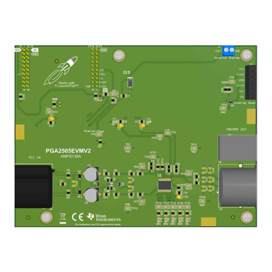
Page 14: Pcb Layout
Schematic, PCB Layout, and Bill of Materials www.ti.com 6.2 PCB Layout The PGA2505EVMV2 is a four-layer printed circuit board using both through-hole and surface-mount components. Figure 6-2. PGA2505EVMV2 Top Overlay PGA2505EVMV2 Evaluation Module SBOU259 – OCTOBER 2021 Submit Document Feedback... -
Page 15: Figure 6-3. Pga2505Evmv2 Top Layer
Schematic, PCB Layout, and Bill of Materials Figure 6-3. PGA2505EVMV2 Top Layer Figure 6-4. PGA2505EVMV2 Bottom Layer SBOU259 – OCTOBER 2021 PGA2505EVMV2 Evaluation Module Submit Document Feedback Copyright © 2021 Texas Instruments Incorporated... -
Page 16: Bill Of Materials
Schematic, PCB Layout, and Bill of Materials www.ti.com 6.3 Bill of Materials Table 6-1 lists the complete bill of materials for the PGA2505EVMV2. Data for each component is available from the corresponding manufacturer’s web site. Table 6-1. PGA2505EVMV2 BOM Designator... - Page 17 Schematic, PCB Layout, and Bill of Materials Table 6-1. PGA2505EVMV2 BOM (continued) Designator Quantity Value Description Package Reference Part Number Manufacturer Receptacle, Male, 3 Position, R/A, TH Receptacle, Male, 3 Position, PQG3MRA112 Switchcraft R/A, TH J5, J7 Receptacle, 2.54mm, 10x2, Tin, TH...
- Page 18 STANDARD TERMS FOR EVALUATION MODULES Delivery: TI delivers TI evaluation boards, kits, or modules, including any accompanying demonstration software, components, and/or documentation which may be provided together or separately (collectively, an “EVM” or “EVMs”) to the User (“User”) in accordance with the terms set forth herein.
- Page 19 www.ti.com Regulatory Notices: 3.1 United States 3.1.1 Notice applicable to EVMs not FCC-Approved: FCC NOTICE: This kit is designed to allow product developers to evaluate electronic components, circuitry, or software associated with the kit to determine whether to incorporate such items in a finished product and software developers to write software applications for use with the end product.
- Page 20 www.ti.com Concernant les EVMs avec antennes détachables Conformément à la réglementation d'Industrie Canada, le présent émetteur radio peut fonctionner avec une antenne d'un type et d'un gain maximal (ou inférieur) approuvé pour l'émetteur par Industrie Canada. Dans le but de réduire les risques de brouillage radioélectrique à...
- Page 21 www.ti.com EVM Use Restrictions and Warnings: 4.1 EVMS ARE NOT FOR USE IN FUNCTIONAL SAFETY AND/OR SAFETY CRITICAL EVALUATIONS, INCLUDING BUT NOT LIMITED TO EVALUATIONS OF LIFE SUPPORT APPLICATIONS. 4.2 User must read and apply the user guide and other available documentation provided by TI regarding the EVM prior to handling or using the EVM, including without limitation any warning or restriction notices.
- Page 22 Notwithstanding the foregoing, any judgment may be enforced in any United States or foreign court, and TI may seek injunctive relief in any United States or foreign court. Mailing Address: Texas Instruments, Post Office Box 655303, Dallas, Texas 75265 Copyright © 2019, Texas Instruments Incorporated...
- Page 23 TI products. TI’s provision of these resources does not expand or otherwise alter TI’s applicable warranties or warranty disclaimers for TI products. TI objects to and rejects any additional or different terms you may have proposed. IMPORTANT NOTICE Mailing Address: Texas Instruments, Post Office Box 655303, Dallas, Texas 75265 Copyright © 2021, Texas Instruments Incorporated...
Need help?
Do you have a question about the PGA2505EVMV2 and is the answer not in the manual?
Questions and answers