Advertisement
Quick Links
This user's guide describes the function and use of the PCM1808EVM. This document includes the
hardware configuration instructions, a quick-start guide, jumper and connector descriptions, schematics,
and printed-circuit board (PCB) layout that demonstrate TI's recommended practices for these devices.
...................................................................................................................
1
2
3
4
5
6
Schematic and Bill of Materials
7
Related Documentation
1
2
3
PCM1808EVM Power Plane 2
4
PCM1808EVM Bottom Layer
5
PCM1808EVM Schematic
1
PCM1808EVM Headers and Jumpers
2
PCM1808 Mode Settings
3
PCM1808 Format Settings
4
Trademarks
All trademarks are the property of their respective owners.
SBAU349 - June 2020
Submit Documentation Feedback
.................................................................................................................
.....................................................................................................
...................................................................................................
.................................................................................................................
............................................................................................
.....................................................................................................
..................................................................................................
.............................................................................................
.............................................................................................
..............................................................................................
..................................................................................................
....................................................................................
...................................................................................................
.................................................................................................
...............................................................................................................
Copyright © 2020, Texas Instruments Incorporated
PCM1808 Evaluation Module
Contents
List of Figures
List of Tables
User's Guide
SBAU349 - June 2020
PCM1808 Evaluation Module
2
2
2
3
4
7
8
4
5
5
6
7
2
2
3
8
1
Advertisement

Subscribe to Our Youtube Channel
Related Manuals for Texas Instruments PCM1808EVM


Summary of Contents for Texas Instruments PCM1808EVM
-
Page 1: Table Of Contents
SBAU349 – June 2020 PCM1808 Evaluation Module This user's guide describes the function and use of the PCM1808EVM. This document includes the hardware configuration instructions, a quick-start guide, jumper and connector descriptions, schematics, and printed-circuit board (PCB) layout that demonstrate TI's recommended practices for these devices. -
Page 2: Introduction
5-V supply. Access to the converter output is provided on the audio serial interface in I2S and LJ formats. Power Supply The PCM1808EVM is powered with a single 5-V power supply connected to J11. An onboard low-dropout regulator converts the 5-V supply to the 3.3-V rail used by the ADC. The analog supply, VCC, is fixed at 5- V and the digital supply, VDD, at 3.3 V. -
Page 3: Interfacing With The Evm
Interfacing With the EVM PCM1808EVM Inputs The right and left audio inputs to the PCM1808EVM can be applied through the RCA connectors (J9 and J10, respectively) or directly to the test points (TP4 and TP5, respectively). The single-ended audio inputs pass through an optional anti-aliasing filter made by R9 and C8 for the right input and R10 and C10 for the left input. -
Page 4: Board Layout
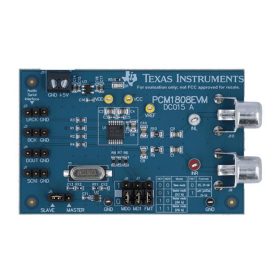
Board Layout www.ti.com Board Layout Figure 1 Figure 4 illustrate the EVM board layout. Figure 1. PCM1808EVM Top Layer PCM1808 Evaluation Module SBAU349 – June 2020 Submit Documentation Feedback Copyright © 2020, Texas Instruments Incorporated... -
Page 5: Pcm1808Evm Power Plane
Board Layout www.ti.com Figure 2. PCM1808EVM Power Plane 1 Figure 3. PCM1808EVM Power Plane 2 SBAU349 – June 2020 PCM1808 Evaluation Module Submit Documentation Feedback Copyright © 2020, Texas Instruments Incorporated... - Page 6 Board Layout www.ti.com Figure 4. PCM1808EVM Bottom Layer PCM1808 Evaluation Module SBAU349 – June 2020 Submit Documentation Feedback Copyright © 2020, Texas Instruments Incorporated...
- Page 7 Schematic and Bill of Materials This section contains the EVM schematic and bill of materials. Schematic Figure 5 illustrates the EVM schematic. Figure 5. PCM1808EVM Schematic SBAU349 – June 2020 PCM1808 Evaluation Module Submit Documentation Feedback Copyright © 2020, Texas Instruments Incorporated...
-
Page 8: Bill Of Materials
SOT-23 (DBV), -40 to 85 degC, Green (RoHS & no Sb/Br) Crystal, 12.288 MHz, 20 pF, SMD ECS-122.8-20-5PX-TR ECS Inc. Related Documentation 1. Texas Instruments, PCM1808 Single-Ended, Analog-Input 24-Bit, 96-kHz Stereo ADC Data Sheet PCM1808 Evaluation Module SBAU349 – June 2020 Submit Documentation Feedback Copyright © 2020, Texas Instruments Incorporated... - Page 9 STANDARD TERMS FOR EVALUATION MODULES Delivery: TI delivers TI evaluation boards, kits, or modules, including any accompanying demonstration software, components, and/or documentation which may be provided together or separately (collectively, an “EVM” or “EVMs”) to the User (“User”) in accordance with the terms set forth herein.
- Page 10 www.ti.com Regulatory Notices: 3.1 United States 3.1.1 Notice applicable to EVMs not FCC-Approved: FCC NOTICE: This kit is designed to allow product developers to evaluate electronic components, circuitry, or software associated with the kit to determine whether to incorporate such items in a finished product and software developers to write software applications for use with the end product.
- Page 11 www.ti.com Concernant les EVMs avec antennes détachables Conformément à la réglementation d'Industrie Canada, le présent émetteur radio peut fonctionner avec une antenne d'un type et d'un gain maximal (ou inférieur) approuvé pour l'émetteur par Industrie Canada. Dans le but de réduire les risques de brouillage radioélectrique à...
- Page 12 www.ti.com EVM Use Restrictions and Warnings: 4.1 EVMS ARE NOT FOR USE IN FUNCTIONAL SAFETY AND/OR SAFETY CRITICAL EVALUATIONS, INCLUDING BUT NOT LIMITED TO EVALUATIONS OF LIFE SUPPORT APPLICATIONS. 4.2 User must read and apply the user guide and other available documentation provided by TI regarding the EVM prior to handling or using the EVM, including without limitation any warning or restriction notices.
- Page 13 Notwithstanding the foregoing, any judgment may be enforced in any United States or foreign court, and TI may seek injunctive relief in any United States or foreign court. Mailing Address: Texas Instruments, Post Office Box 655303, Dallas, Texas 75265 Copyright © 2019, Texas Instruments Incorporated...
- Page 14 TI products. TI’s provision of these resources does not expand or otherwise alter TI’s applicable warranties or warranty disclaimers for TI products. Mailing Address: Texas Instruments, Post Office Box 655303, Dallas, Texas 75265 Copyright © 2020, Texas Instruments Incorporated...
Need help?
Do you have a question about the PCM1808EVM and is the answer not in the manual?
Questions and answers