Advertisement
Quick Links
www.ti.com
EVM User's Guide: DRV8421AEVM, DRV8421BEVM
DRV8421x Evaluation Module
Description
The DRV8421xEVM allows for easy evaluating of the
DRV8421 dual H-bridge motor driver. The evaluation
module (EVM) can support the DGQ and DFU
packages of the DRV8421A and DRV8421B device
variants. However, only one variant and package can
be populated at a time since the input control signals
(MCU Ctrl 1 and MCU Ctrl 2) are shared among the
devices.
The DRV8421xEVM can drive one or two brushed-DC
motors, or a single bipolar stepper motor. The two
onboard potentiometers provide a convenient way to
manually adjust speed and direction on the fly, an
excellent choice for prototyping and evaluating new
designs.
Get Started
1. Order the EVM:
DRV8421BEVM
2. Download the data sheet:
SLOU571 – JUNE 2024
Submit Document Feedback
SLVSHA4
DRV8421xEVM
Copyright © 2024 Texas Instruments Incorporated
Features
•
DRV8421 is a dual H-bridge motor driver
•
Two device versions:
– DRV8421A (4-wire input): independent half-
bridge control
– DRV8421B (2-Wire Input): sleep mode, fault
detection
•
PWM control interface
•
Onboard 3.3V LDO for digital voltage supply
•
Main signal header with removable shunts to
disconnect main signals going to the motor driver
IC from the MCU
Applications
•
Household appliances
–
Printers and Scanners
–
Refrigerators
–
Vacuum cleaners
–
Clothes dryer
•
General brushed and stepper motors
Description
DRV8421x Evaluation Module
1
Advertisement

Related Manuals for Texas Instruments DRV8421 Series


Summary of Contents for Texas Instruments DRV8421 Series
- Page 1 – Vacuum cleaners 1. Order the EVM: DRV8421BEVM – Clothes dryer 2. Download the data sheet: SLVSHA4 • General brushed and stepper motors DRV8421xEVM SLOU571 – JUNE 2024 DRV8421x Evaluation Module Submit Document Feedback Copyright © 2024 Texas Instruments Incorporated...
- Page 2 The documents in Table 1-2 provide information regarding Texas Instruments integrated circuits used in the assembly of the EVM. This user's guide is available from the TI web site under literature number SLOU571. Any letter appended to the literature number corresponds to the document revision that is current at the time of the writing of this document.
- Page 3 Select Full-Step or Half-Step when in Stepper Mode Remove shunt 3 from J7 to use to populate J11 (See Section Parallel mode jumper Parallel mode jumper 2.1.7 for more details) SLOU571 – JUNE 2024 DRV8421x Evaluation Module Submit Document Feedback Copyright © 2024 Texas Instruments Incorporated...
- Page 4 J2: Populated for brushed-DC motor mode • J7: All populated for MCU communication with DRV8421 Figure 2-2. Jumper Configuration for Brushed-DC Control with DRV8421A DRV8421x Evaluation Module SLOU571 – JUNE 2024 Submit Document Feedback Copyright © 2024 Texas Instruments Incorporated...
- Page 5 J10: Select Full-Step or Half-Step sequence (Blue: Full-Step, Red: Half-Step) • J7: All populated for MCU communication with DRV8421 Figure 2-3. Jumper Configuration for Stepper Motor Control with DRV8421A SLOU571 – JUNE 2024 DRV8421x Evaluation Module Submit Document Feedback Copyright © 2024 Texas Instruments Incorporated...
- Page 6 J1: Select enable or sleep configuration (blue: enables device, red: low-power sleep mode) • J7: All populated for MCU communication with DRV8421 Figure 2-4. Jumper Configuration for Brushed-DC Motor Control with DRV8421B DRV8421x Evaluation Module SLOU571 – JUNE 2024 Submit Document Feedback Copyright © 2024 Texas Instruments Incorporated...
- Page 7 MCU Ctrl 1 and MCU Ctrl 2 potentiometers. To achieve a 1 or 0 for the outputs, the input potentiometers must be turned completely clockwise or counterclockwise. The table below shows how to configure the potentiometers for different modes of operation. SLOU571 – JUNE 2024 DRV8421x Evaluation Module Submit Document Feedback Copyright © 2024 Texas Instruments Incorporated...
- Page 8 Separate firmware must be configured on an external MCU with inputs connected to J7 to utilize all four outputs with independent half-bridge control. Figure 2-6. EVM Controls for Brushed-DC Motor Operation with DRV8421A DRV8421x Evaluation Module SLOU571 – JUNE 2024 Submit Document Feedback Copyright © 2024 Texas Instruments Incorporated...
- Page 9 When operating in Stepper Mode (J2) and Step Select (J10), the speed of the stepper motor is controlled by MCU Ctrl 1 potentiometer. Figure 2-8. EVM Controls for Stepper Motor Operation with DRV8421A SLOU571 – JUNE 2024 DRV8421x Evaluation Module Submit Document Feedback Copyright © 2024 Texas Instruments Incorporated...
- Page 10 The following figure shows an example of input and output waveforms while in half-step mode. This step sequence is only available through the Step Select jumper (J10) for the DRV8421A only. Figure 2-10. Half-Step Sequence Waveforms DRV8421x Evaluation Module SLOU571 – JUNE 2024 Submit Document Feedback Copyright © 2024 Texas Instruments Incorporated...
- Page 11 Forward counter- clockwise High – turn MCU CTRL 1 Channel 2 Reverse completely clockwise Figure 2-11. EVM Controls for Brushed-DC Motor Operation with DRV8421B SLOU571 – JUNE 2024 DRV8421x Evaluation Module Submit Document Feedback Copyright © 2024 Texas Instruments Incorporated...
- Page 12 MCU Ctrl 1 potentiometer. The DRV8421B is configured in a full-step sequence by default and the Step Select (J10) jumper must not be populated. Figure 2-13. EVM Controls for Stepper Motor Operation with DRV8421B DRV8421x Evaluation Module SLOU571 – JUNE 2024 Submit Document Feedback Copyright © 2024 Texas Instruments Incorporated...
- Page 13 Use external wire connections While in parallel mode, the speed adjust comes from the MCU Ctrl 1 input potentiometer. Figure 2-14. Parallel Mode Operation with DRV8421B SLOU571 – JUNE 2024 DRV8421x Evaluation Module Submit Document Feedback Copyright © 2024 Texas Instruments Incorporated...
- Page 14 Solder the device to footprint U1. Make sure pin 1 of device aligns with the dot on the PCB. DRV8421BDFU • If not already de-populated, de-populate R5. • If not already populated, populate R2 (0603, 10kΩ). DRV8421x Evaluation Module SLOU571 – JUNE 2024 Submit Document Feedback Copyright © 2024 Texas Instruments Incorporated...
- Page 15 Hardware Figure 2-15. Device ID Resistors SLOU571 – JUNE 2024 DRV8421x Evaluation Module Submit Document Feedback Copyright © 2024 Texas Instruments Incorporated...
- Page 16 Unknown revision Assembly Variant: Sheet: warrant that this design will meet the specifications, will be suitable for your application or fit for any particular purpose, or will operate in an implementation. Texas Instruments and/or its Drawn By: David Medis File: MD077A.SchDoc...
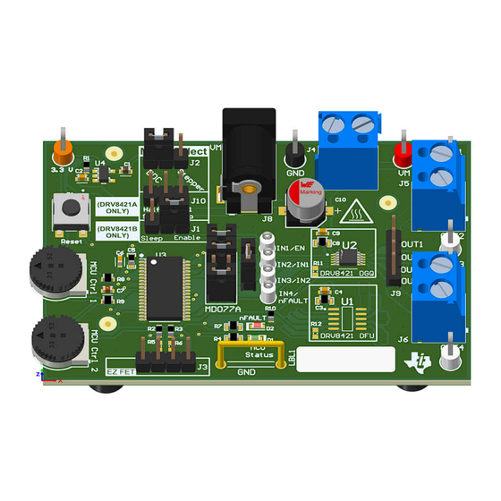
- Page 17 Hardware Design Files 3.2 PCB (Top-Assembly View) Figure 3-2. PCB (Top 3-D View) Figure 3-3. PCB (Top-Assembly View) SLOU571 – JUNE 2024 DRV8421x Evaluation Module Submit Document Feedback Copyright © 2024 Texas Instruments Incorporated...
- Page 18 Hardware Design Files www.ti.com Figure 3-4. PCB (Bottom-Assembly View) DRV8421x Evaluation Module SLOU571 – JUNE 2024 Submit Document Feedback Copyright © 2024 Texas Instruments Incorporated...
- Page 19 RES, 330, 5%, 0.1 W, 0603 0603 RC0603JR-07330RL RES, 47 k, 5%, 0.1 W, AEC-Q200 Grade 0, 0603 0603 CRCW060347K0JNEA RP1, RP2 Trimming Potentiometer, 50K, 0.5W, TH 9.53x8.89mm 3352T-1-503LF SLOU571 – JUNE 2024 DRV8421x Evaluation Module Submit Document Feedback Copyright © 2024 Texas Instruments Incorporated...
- Page 20 40V Ultralow-Iq Low-Dropout Regulator, DBV0005A DBV0005A TPS7B6933DBVR (SOT-23-5) R5, R6, R11, R12 RES, 10 k, 5%, 0.1 W, 0603 0603 RC0603JR-0710KL Dual H-Bridge Stepper Driver, SSOP10 SSOP10 DRV8421ADFUR DRV8421x Evaluation Module SLOU571 – JUNE 2024 Submit Document Feedback Copyright © 2024 Texas Instruments Incorporated...
- Page 21 Additional Information 4 Additional Information 4.1 Trademarks All trademarks are the property of their respective owners. SLOU571 – JUNE 2024 DRV8421x Evaluation Module Submit Document Feedback Copyright © 2024 Texas Instruments Incorporated...
- Page 22 STANDARD TERMS FOR EVALUATION MODULES Delivery: TI delivers TI evaluation boards, kits, or modules, including any accompanying demonstration software, components, and/or documentation which may be provided together or separately (collectively, an “EVM” or “EVMs”) to the User (“User”) in accordance with the terms set forth herein.
- Page 23 www.ti.com Regulatory Notices: 3.1 United States 3.1.1 Notice applicable to EVMs not FCC-Approved: FCC NOTICE: This kit is designed to allow product developers to evaluate electronic components, circuitry, or software associated with the kit to determine whether to incorporate such items in a finished product and software developers to write software applications for use with the end product.
- Page 24 www.ti.com Concernant les EVMs avec antennes détachables Conformément à la réglementation d'Industrie Canada, le présent émetteur radio peut fonctionner avec une antenne d'un type et d'un gain maximal (ou inférieur) approuvé pour l'émetteur par Industrie Canada. Dans le but de réduire les risques de brouillage radioélectrique à...
- Page 25 www.ti.com EVM Use Restrictions and Warnings: 4.1 EVMS ARE NOT FOR USE IN FUNCTIONAL SAFETY AND/OR SAFETY CRITICAL EVALUATIONS, INCLUDING BUT NOT LIMITED TO EVALUATIONS OF LIFE SUPPORT APPLICATIONS. 4.2 User must read and apply the user guide and other available documentation provided by TI regarding the EVM prior to handling or using the EVM, including without limitation any warning or restriction notices.
- Page 26 Notwithstanding the foregoing, any judgment may be enforced in any United States or foreign court, and TI may seek injunctive relief in any United States or foreign court. Mailing Address: Texas Instruments, Post Office Box 655303, Dallas, Texas 75265 Copyright © 2023, Texas Instruments Incorporated...
- Page 27 TI products. TI’s provision of these resources does not expand or otherwise alter TI’s applicable warranties or warranty disclaimers for TI products. TI objects to and rejects any additional or different terms you may have proposed. IMPORTANT NOTICE Mailing Address: Texas Instruments, Post Office Box 655303, Dallas, Texas 75265 Copyright © 2024, Texas Instruments Incorporated...
Need help?
Do you have a question about the DRV8421 Series and is the answer not in the manual?
Questions and answers