Table of Contents
Advertisement
Quick Links
User's Guide for bq25505 Battery Charger Evaluation
This user's guide describes the bq25505 evaluation module (EVM), how to perform a stand-alone
evaluation and how to allow the EVM to interface with the system and host. The boost charger output is
configured to deliver up to 4.2-V maximum voltage to its output, VSTOR, using external resistors. This
voltage is applied to the storage element as long as the storage element voltage at VBAT_SEC is above
the internally programmed undervoltage of 2 V. The VBAT_OK indicator toggles high when VSTOR ramps
up to 3 V and toggles low when VSTOR ramps down to 2.8 V.
...................................................................................................................
1
1.1
1.2
1.3
1.4
1.5
2
3
3.1
4
4.1
4.2
5
1
bq25505EVM Schematic
2
3
4
5
6
...................................................................................................................
7
8
9
10
11
12
13
14
1
I/O Connections and Configuration for Evaluation of bq25505 EVM
2
Bill of Materials
SLUUAA8 - September 2013
Submit Documentation Feedback
.......................................................................................................
................................................................................................
...........................................................................................
..............................................................................................
...............................................................................
.........................................................................................
...........................................................................................
.......................................................................................
....................................................................................................
................................................................................................
.....................................................................................................
....................................................................................................
..................................................................................
..................................................................................
.................................................................................
.........................................................................................................
..................................................................................................
......................................................................................................
...................................................................................................
.............................................................................................................
User's Guide for bq25505 Battery Charger Evaluation Module for Energy
Copyright © 2013, Texas Instruments Incorporated
Module for Energy Harvesting
Contents
..........................................................................
List of Figures
....................................................................
..........................................................................
...........................................................
..........................................................................
..........................................................
List of Tables
.................................................
User's Guide
SLUUAA8 - September 2013
2
2
2
3
4
5
7
7
8
14
14
15
19
4
8
9
9
10
10
11
12
12
13
15
16
17
18
5
14
1
Harvesting
Advertisement
Table of Contents

Related Manuals for Texas Instruments bq25505


Summary of Contents for Texas Instruments bq25505
-
Page 1: Table Of Contents
User's Guide for bq25505 Battery Charger Evaluation Module for Energy Harvesting This user’s guide describes the bq25505 evaluation module (EVM), how to perform a stand-alone evaluation and how to allow the EVM to interface with the system and host. The boost charger output is configured to deliver up to 4.2-V maximum voltage to its output, VSTOR, using external resistors. -
Page 2: Sluuaa8 – September
(MPPT) sampling network to optimize the transfer of power into the device. The bq25505 periodically samples the open circuit input voltage every 16 seconds by disabling the boost converter for 256 ms and stores the programmed MPP ratio of the OC voltage on the external reference capacitor (C2) at VREF_SAMP. -
Page 3: Design And Evaluation Considerations
(VBAT_UV) and user programmed overvoltage (VBAT_OV) levels. To further assist users in the strict management of their energy budgets, the bq25505 toggles a user programmable battery good flag (VBAT_OK), checked every 64 ms, to signal the microprocessor when the voltage on an energy storage element or capacitor has risen above (OK_HYST threshold) or dropped below (OK_PROG threshold) a pre-set critical level. -
Page 4: Bq25505Evm Schematic
Q2-A Q2-B 0.01uF 5.76M 5.36M BAT_SEC VB_PRI_ON BAT_SEC Not Installed Figure 1. bq25505EVM Schematic white white User's Guide for bq25505 Battery Charger Evaluation Module for Energy SLUUAA8 – September 2013 Harvesting Submit Documentation Feedback Copyright © 2013, Texas Instruments Incorporated... -
Page 5: Evm I/O Connections
Introduction www.ti.com EVM I/O Connections Table 1. I/O Connections and Configuration for Evaluation of bq25505 EVM REFERENCE DESCRIPTION COMMENTS / DEFAULT SETTINGS DESIGNATOR HEADERS AND TERMINALS J1 – VIN Input source (+) If VIN_DC is higher than VSTOR and VSTOR is equal to VBAT_OV, the input VIN_DC is pulled to ground through a small resistance to stop further charging of the attached battery or capacitor. - Page 6 Introduction www.ti.com Table 1. I/O Connections and Configuration for Evaluation of bq25505 EVM (continued) REFERENCE DESCRIPTION COMMENTS / DEFAULT SETTINGS DESIGNATOR JUMPERS JP1 – VOC_SAMP VOC_SAMP = external resistors sized to configure the IC Uninstalled (NOTE: Do not install if JP4 shunt is installed)
-
Page 7: Evm Performance Specification Summary
BAT pin via a diode. The lab supply biases up the battery voltage to the desired level. It may be necessary to add more capacitance across R1. SLUUAA8 – September 2013 User's Guide for bq25505 Battery Charger Evaluation Module for Energy Harvesting Submit Documentation Feedback... -
Page 8: Test Setups And Results
(that is, MPPT% × VOC) Figure 2. Test Setup for Measuring Boost Charger Efficiency User's Guide for bq25505 Battery Charger Evaluation Module for Energy SLUUAA8 – September 2013 Harvesting Submit Documentation Feedback Copyright © 2013, Texas Instruments Incorporated... -
Page 9: Charger Efficiency Versus Input Voltage
2. The boost charger inductor current (IL) was measured by using an oscilloscope current probe across a current loop that was inserted in series with inductor L1. SLUUAA8 – September 2013 User's Guide for bq25505 Battery Charger Evaluation Module for Energy Harvesting Submit Documentation Feedback... -
Page 10: Test Setup For Measuring Charger Operation
75 : 75 : Figure 5. Test Setup for Measuring Charger Operation Figure 6. Charger Operational Waveforms During Battery Charging User's Guide for bq25505 Battery Charger Evaluation Module for Energy SLUUAA8 – September 2013 Harvesting Submit Documentation Feedback Copyright © 2013, Texas Instruments Incorporated... -
Page 11: Test Setup
3. VBAT_SEC, VBAT_PRI, VBAT_OK and VOR were measured with oscilloscope voltage probes at TP5, TP6, J13 and J14, respectively. Function Generator Power Amplifier 1 k: Figure 7. Test Setup SLUUAA8 – September 2013 User's Guide for bq25505 Battery Charger Evaluation Module for Energy Harvesting Submit Documentation Feedback Copyright © 2013, Texas Instruments Incorporated... -
Page 12: Switching From Primary To Secondary Battery
120mF IOUT =1.0 mA COMP=1.2 V Figure 9. Test Setup for Charging a Super Capacitor on VBAT_SEC User's Guide for bq25505 Battery Charger Evaluation Module for Energy SLUUAA8 – September 2013 Harvesting Submit Documentation Feedback Copyright © 2013, Texas Instruments Incorporated... -
Page 13: Charging A Super Cap On Vbat_Sec
No other connections should be made to the EVM and the measurement should be taken after steady state conditions are reached (may take a few minutes). The reading should be much less than 100 SLUUAA8 – September 2013 User's Guide for bq25505 Battery Charger Evaluation Module for Energy Harvesting Submit Documentation Feedback... -
Page 14: Bill Of Materials And Board Layout
IC, Ultra-Low Power Harvester Charger VQFN BQ25505RGR Shunt, 100-mil, Black 929950-00 PCB, 2.5212 in x 2.6039 in PWR218 User's Guide for bq25505 Battery Charger Evaluation Module for Energy SLUUAA8 – September 2013 Harvesting Submit Documentation Feedback Copyright © 2013, Texas Instruments Incorporated... -
Page 15: Evm Board Layout
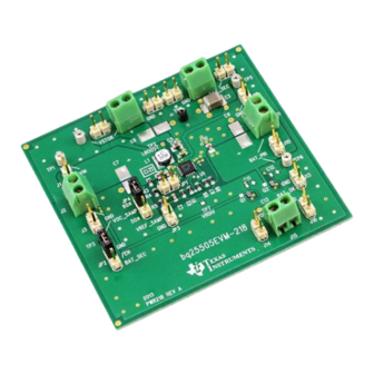
BAT_PRI VREF_SAMP VRDIV BAT_SEC BAT_OK bq25505EVM-218 2013 PWR218 REV A Figure 11. EVM PCB Top Silk SLUUAA8 – September 2013 User's Guide for bq25505 Battery Charger Evaluation Module for Energy Harvesting Submit Documentation Feedback Copyright © 2013, Texas Instruments Incorporated... -
Page 16: Evm Pcb Top Assembly
Bill of Materials and Board Layout www.ti.com Figure 12. EVM PCB Top Assembly User's Guide for bq25505 Battery Charger Evaluation Module for Energy SLUUAA8 – September 2013 Harvesting Submit Documentation Feedback Copyright © 2013, Texas Instruments Incorporated... -
Page 17: Evm Pcb Top Layer
Bill of Materials and Board Layout www.ti.com Figure 13. EVM PCB Top Layer SLUUAA8 – September 2013 User's Guide for bq25505 Battery Charger Evaluation Module for Energy Harvesting Submit Documentation Feedback Copyright © 2013, Texas Instruments Incorporated... -
Page 18: Evm Pcb Bottom Layer
Bill of Materials and Board Layout www.ti.com Figure 14. EVM PCB Bottom Layer User's Guide for bq25505 Battery Charger Evaluation Module for Energy SLUUAA8 – September 2013 Harvesting Submit Documentation Feedback Copyright © 2013, Texas Instruments Incorporated... -
Page 19: Pcb Layout Guideline
5X below the measured ionic contamination. SLUUAA8 – September 2013 User's Guide for bq25505 Battery Charger Evaluation Module for Energy Harvesting Submit Documentation Feedback... - Page 20 ADDITIONAL TERMS AND CONDITIONS, WARNINGS, RESTRICTIONS, AND DISCLAIMERS FOR EVALUATION MODULES Texas Instruments Incorporated (TI) markets, sells, and loans all evaluation boards, kits, and/or modules (EVMs) pursuant to, and user expressly acknowledges, represents, and agrees, and takes sole responsibility and risk with respect to, the following: 1.
- Page 21 RADIO FREQUENCY REGULATORY COMPLIANCE INFORMATION FOR EVALUATION MODULES Texas Instruments Incorporated (TI) evaluation boards, kits, and/or modules (EVMs) and/or accompanying hardware that is marketed, sold, or loaned to users may or may not be subject to radio frequency regulations in specific countries.
- Page 22 Les types d'antenne non inclus dans cette liste, ou dont le gain est supérieur au gain maximal indiqué, sont strictement interdits pour l'exploitation de l'émetteur. Mailing Address: Texas Instruments, Post Office Box 655303, Dallas, Texas 75265 Copyright © 2014, Texas Instruments Incorporated spacer Important Notice for Users of EVMs Considered “Radio Frequency Products”...
- Page 23 IMPORTANT NOTICE Texas Instruments Incorporated and its subsidiaries (TI) reserve the right to make corrections, enhancements, improvements and other changes to its semiconductor products and services per JESD46, latest issue, and to discontinue any product or service per JESD48, latest issue.
Need help?
Do you have a question about the bq25505 and is the answer not in the manual?
Questions and answers