Table of Contents
Advertisement
Quick Links
www.ti.com
EVM User's Guide: AMC7908EVM
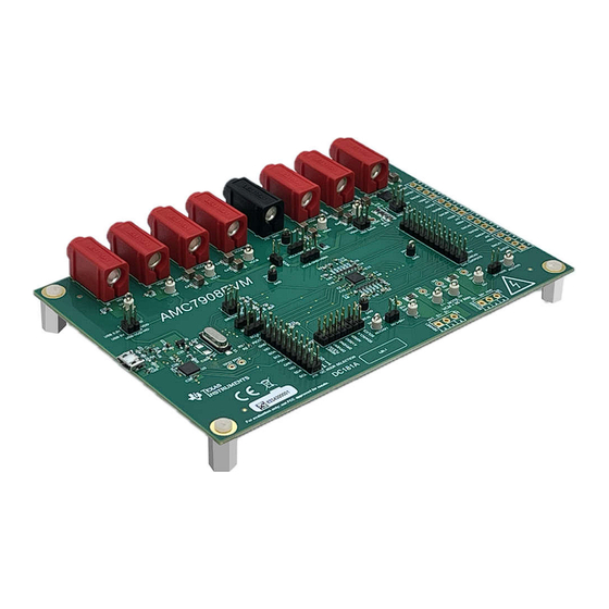
AMC7908 Evaluation Module
Description
The AMC7908EVM is an easy-to-use platform to
evaluate the functionality and performance of the
AMC7908 device. The AMC7908EVM has optional
circuits and jumpers to configure the device for
different applications.
The AMC7908 is a highly integrated power-amplifier
monitor and control device with eight 13-bit digital-
to-analog converters (DAC) and a 12-bit analog-to-
digital converter (ADC). The DACs can be switched
on and off through dedicated clamping software and
hardware triggers.
Get Started
1. Order the EVM.
2. Configure EVM jumpers.
3. Install the AMC7908EVM GUI from ti.com.
4. Download the latest libraries.
SLAU883A – MARCH 2024 – REVISED JUNE 2024
Submit Document Feedback
5. Connect USB and external power supplies.
6. Launch the AMC7908EVM GUI.
Features
•
Configurable circuit to evaluate the AMC7908
•
Onboard VDD (5V) and VIO (3.3V) support via
USB
•
Onboard VSSA and VSSB (−10.5V or −7V)
support
•
FT4222 easily writes to the AMC using the
AMC7908EVM GUI
•
External SPI and I
Applications
•
Macro remote radio unit (RRU)
•
Active antenna system mMIMO (AAS)
•
Outdoor backhaul unit
•
Radar
Copyright © 2024 Texas Instruments Incorporated
Description
2
C connections available
AMC7908 Evaluation Module
1
Advertisement
Table of Contents

Related Manuals for Texas Instruments AMC7908EVM


Summary of Contents for Texas Instruments AMC7908EVM
- Page 1 EVM User's Guide: AMC7908EVM AMC7908 Evaluation Module 5. Connect USB and external power supplies. Description 6. Launch the AMC7908EVM GUI. The AMC7908EVM is an easy-to-use platform to Features evaluate the functionality and performance of the AMC7908 device. The AMC7908EVM has optional •...
-
Page 2: Kit Contents
Texas Instruments integrated circuits used in the assembly of the AMC7908EVM. This user's guide is available from the TI web site under literature number SLAU883. Any letter appended to the literature number corresponds to the document revision that is current at the time of the writing of this document. -
Page 3: Hardware Theory Of Operation
VCCA and VCCB supplies. 2.1.1 Hardware Theory of Operation The AMC7908EVM is connected to the computer through the on-board FTDI digital controller using the USB cable that is supplied with the EVM. The evaluation board features connectors and test points for all communication lines, DAC outputs, supplies, and the ADC inputs. -
Page 4: Jumper Definitions
J14, J15, J20, J21, J26, and J27 are optional terminal blocks. See Table 2-4 for more information. 2.1.2 Jumper Definitions Table 2-1 provides the details of the configurable jumper settings of the AMC7908EVM. Figure 2-2 shows the default jumper connections on the board. Table 2-1. Jumper Definitions... - Page 5 Hardware Figure 2-2. AMC7908EVM Default Jumpers SLAU883A – MARCH 2024 – REVISED JUNE 2024 AMC7908 Evaluation Module Submit Document Feedback Copyright © 2024 Texas Instruments Incorporated...
-
Page 6: Connector Definitions
Apply a positive voltage to VCCB and ground VSSB for the group B DACs, and apply a negative voltage to VSSA and ground VCCA for the group A DACs. Table 2-3 shows the DAC output header J16 definitions for the AMC7908EVM. Table 2-3. DAC Output Header J16 Definitions Definition... -
Page 7: Test Points
Hardware Table 2-4 shows other connector definitions for the AMC7908EVM. All of these terminal blocks are unpopulated by default. Table 2-4. Terminal Block Connector Definitions Designator Definition Connector for DACA3, OUTA2, DACA2, and VSSA Connector for DACA1, OUTA1, DACA0, and... -
Page 8: Hardware Overview
2.2.1 Electrostatic Discharge Caution CAUTION Many of the components on the AMC7908EVM are susceptible to damage by electrostatic discharge (ESD). Customers are advised to observe proper ESD handling precautions when unpacking and handling the EVM, including the use of a grounded wrist strap at an approved ESD workstation. - Page 9 Hardware 2.2.4 I C Configuration Figure 2-4 shows the AMC7908EVM configured for I C communication. Figure 2-4. AMC7908EVM Configuration I The jumper connections on J19 determine the device address of the AMC7908. Table 2-7 shows the required configuration of the A1 and A0 jumpers for specific device addresses.
-
Page 10: Software Installation
AMC7908EVM GUI software on your PC. The software installation automatically copies the required LabVIEW ™ software files and drivers to the PC. When the AMC7908EVM GUI is launched, an installation dialog window opens and prompts the user to select an installation directory. If left unchanged, Figure 3-1 shows that the software location defaults to C:\Program Files (x86)\Texas Instruments\AMC7908EVM. - Page 11 Figure 3-2 shows the FTDI USB drivers installation window that is automatically launched after the AMC7908EVM software installation is complete. Restart the PC to finish installation. Figure 3-2. FTDI USB Drivers SLAU883A – MARCH 2024 – REVISED JUNE 2024...
-
Page 12: Software Overview
Software www.ti.com 3.2 Software Overview This section discusses how to use the AMC7908EVM software. 3.2.1 Launching the Software If installed in the default directory, launch the AMC7908EVM software by searching for "AMC7908EVM" in the Windows ® Start menu. Figure 3-3 shows the initial configuration menu that is present when the GUI is launched. - Page 13 Figure 3-5 illustrates the bottom-left corner of the GUI that shows the hardware connection status: DEMO MODE or CONNECTED. After the FTDI controller is properly connected to the PC, restart the AMC7908EVM software to detect the device. Figure 3-5. FTDI Digital Controller Connection Status SLAU883A –...
-
Page 14: Software Features
3.2.2.1 Low Level Configuration Page Figure 3-6 shows the AMC7908EVM Low Level Configuration page of the AMC7908EVM GUI. This page allows direct access to all registers on the AMC7908. The GUI handles page address management, allowing seamless access to registers. - Page 15 3.2.2.2 High Level Configuration Page The High Level Configuration page is used to set the configuration of the AMC7908EVM GUI. The page is comprised of two tabs: DAC Control and ADC Control. These two tabs act as shortcuts to configure the AMC7908 for basic functionality and testing.
- Page 16 ADC Control tab from the High Level Configuration page. This tab configures and reads data from the ADC in the AMC7908. Figure 3-8. ADC Control Tab of the High Level Configuration Page AMC7908 Evaluation Module SLAU883A – MARCH 2024 – REVISED JUNE 2024 Submit Document Feedback Copyright © 2024 Texas Instruments Incorporated...
- Page 17 Hardware Design Files 4 Hardware Design Files 4.1 Schematics The AMC7908EVM schematics are shown in Figure 4-1 through Figure 4-3. VCCA-GND-VSSA VCCA VSSA VLDO VNEG VLDO VCCA VSSA VNEG 487k 1.50M 10uF 10uF 10uF -7Vsel -10.5Vsel 97.6k 187k VCCB-GND-VSSA...
- Page 18 STEST_RST USB_3.3V DEBUGGER DGND DGND USB_VBUS VBUS_DET BCD_DET UGND UGND FTDI_XSCI XSCI FTDI_XSCO XSCO FT4222HQ-D-R 1.00M 18pF 18pF Figure 4-2. AMC7908EVM FTDI Schematic VCCA VCCA ADCHV0 ADCHV0 SENSE0+ SENSE0+ 1µF SENSE0- SENSE0- DRVEN1 DRVEN1 DACA0 DACA0 1µF OUTA0 OUTA0 DACA1...
- Page 19 Figure 4-7 show the board layout for the AMC7908EVM. Figure 4-4. AMC7908EVM PCB Top Layer Layout Figure 4-5. AMC7908EVM PCB Mid Layer 1 Layout (Ground Plane) SLAU883A – MARCH 2024 – REVISED JUNE 2024 AMC7908 Evaluation Module Submit Document Feedback...
- Page 20 Hardware Design Files www.ti.com Figure 4-6. AMC7908EVM PCB Mid Layer 2 Layout (Ground Plane) Figure 4-7. AMC7908EVM PCB Bottom Layer Layout AMC7908 Evaluation Module SLAU883A – MARCH 2024 – REVISED JUNE 2024 Submit Document Feedback Copyright © 2024 Texas Instruments Incorporated...
- Page 21 Hardware Design Files 4.3 Bill of Materials Table 4-1 lists the AMC7908EVM bill of materials (BOM). Table 4-1. Bill of Materials for the AMC7908EVM Designator Value Description Package Reference Part Number Manufacturer CAP, CERM, 0.1µF, 25V, +/- 20%, X7R, C1, C2 0.1µF...
- Page 22 Hardware Design Files www.ti.com Table 4-1. Bill of Materials for the AMC7908EVM (continued) Designator Value Description Package Reference Part Number Manufacturer J13, J23, J28, J29 Header, 100mil, 2x2, Gold, TH 2x2 Header TSW-102-07-G-D Samtec Header, 100mil, 12x2, Gold, TH 12x2 Header...
- Page 23 Hardware Design Files Table 4-1. Bill of Materials for the AMC7908EVM (continued) Designator Value Description Package Reference Part Number Manufacturer TP6, TP7, TP8, TP9, TP10, TP11, TP12, Test Point, Compact, White, TH White Compact Testpoint 5007 Keystone Electronics TP13, TP18, TP19,...
-
Page 24: Additional Information
NOTE: Page numbers for previous revisions may differ from page numbers in the current version. Changes from Revision * (March 2024) to Revision A (June 2024) Page • First public release............................. AMC7908 Evaluation Module SLAU883A – MARCH 2024 – REVISED JUNE 2024 Submit Document Feedback Copyright © 2024 Texas Instruments Incorporated... - Page 25 STANDARD TERMS FOR EVALUATION MODULES Delivery: TI delivers TI evaluation boards, kits, or modules, including any accompanying demonstration software, components, and/or documentation which may be provided together or separately (collectively, an “EVM” or “EVMs”) to the User (“User”) in accordance with the terms set forth herein.
- Page 26 www.ti.com Regulatory Notices: 3.1 United States 3.1.1 Notice applicable to EVMs not FCC-Approved: FCC NOTICE: This kit is designed to allow product developers to evaluate electronic components, circuitry, or software associated with the kit to determine whether to incorporate such items in a finished product and software developers to write software applications for use with the end product.
- Page 27 www.ti.com Concernant les EVMs avec antennes détachables Conformément à la réglementation d'Industrie Canada, le présent émetteur radio peut fonctionner avec une antenne d'un type et d'un gain maximal (ou inférieur) approuvé pour l'émetteur par Industrie Canada. Dans le but de réduire les risques de brouillage radioélectrique à...
- Page 28 www.ti.com EVM Use Restrictions and Warnings: 4.1 EVMS ARE NOT FOR USE IN FUNCTIONAL SAFETY AND/OR SAFETY CRITICAL EVALUATIONS, INCLUDING BUT NOT LIMITED TO EVALUATIONS OF LIFE SUPPORT APPLICATIONS. 4.2 User must read and apply the user guide and other available documentation provided by TI regarding the EVM prior to handling or using the EVM, including without limitation any warning or restriction notices.
- Page 29 Notwithstanding the foregoing, any judgment may be enforced in any United States or foreign court, and TI may seek injunctive relief in any United States or foreign court. Mailing Address: Texas Instruments, Post Office Box 655303, Dallas, Texas 75265 Copyright © 2023, Texas Instruments Incorporated...
- Page 30 TI products. TI’s provision of these resources does not expand or otherwise alter TI’s applicable warranties or warranty disclaimers for TI products. TI objects to and rejects any additional or different terms you may have proposed. IMPORTANT NOTICE Mailing Address: Texas Instruments, Post Office Box 655303, Dallas, Texas 75265 Copyright © 2024, Texas Instruments Incorporated...
Need help?
Do you have a question about the AMC7908EVM and is the answer not in the manual?
Questions and answers