Table of Contents
Advertisement
Available languages
Available languages
Quick Links
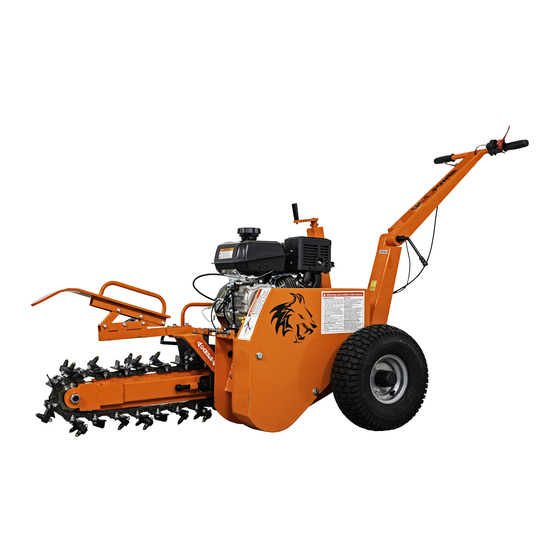
OPT118
18" TRENCHER
18" CUTTING DEPTH • DIRECT DRIVE AUGER • 7 HP KOHLER® ENGINE
STEP 1
ASSEMBLY GUIDE
DK2 USA WEST
DK2 CORPORATE HEAD OFFICE
DK2 USA EAST
4301 S VALLEY VIEW BLVD. SUITE 10-11
1080 CLAY AVENUE, UNIT 2
3750 SOUTH AVENUE, NORTH UNIT
LAS VEGAS, NEVADA
BURLINGTON, ONTARIO
TOLEDO, OHIO
89103 USA
L7L0A1 CANADA
43615 USA
PARTS AND SERVICE 702-331-5353 • WWW.DK2POWER.COM
Advertisement
Chapters
Table of Contents

Related Manuals for DK2 Power OPT118


Summary of Contents for DK2 Power OPT118
- Page 1 OPT118 18” TRENCHER 18” CUTTING DEPTH • DIRECT DRIVE AUGER • 7 HP KOHLER® ENGINE STEP 1 ASSEMBLY GUIDE DK2 USA WEST DK2 CORPORATE HEAD OFFICE DK2 USA EAST 4301 S VALLEY VIEW BLVD. SUITE 10-11 1080 CLAY AVENUE, UNIT 2...
-
Page 2: Table Of Contents
TABLE OF CONTENTS Check the packing ................................ 3 Handle assembly ................................4 Depth control handle ..............................5 Chain drive bar ................................6 Chain installation ................................7 Safety bar installation ..............................8 Auger guard ..................................9 Engine operation, safety and maintenance ......................10 SCHEMATICS AND PARTS Chain system .................................. -
Page 3: Check The Packing
The Trencher is shipped in a crate. Leave the sides folded down and use as your work space. NOTE: UPON INSPECTION OF PARTS, IF YOU FIND ANY DAMAGE OR MISSING PIECES PLEASE CALL DK2 POWER AT 702-331-5353 OR CONTACT US VIA OUR WEBSITE WWW.DK2POWER.COM. WE WILL REPLACE ANY MISSING PARTS TO YOU FOR FREE. -
Page 4: Handle Assembly
STEP 2 HANDLE ASSEMBLY Assemble the handle first. INSTALL with hardware that is supplied for the handle... -
Page 5: Depth Control Handle
STEP 3 DEPTH CONTROL HANDLE Attach the depth control handle. Turn handle to adjust depth... -
Page 6: Chain Drive Bar
STEP 4 CHAIN DRIVE BAR Slide chain drive bar onto support as shown. The cap head bolts will be tightened later after the chain is installed. Adjust bar even after chain install... -
Page 7: Chain Installation
STEP 5 INSTALL THE CHAIN LEAVE 1 INCH SLACK STEP 1: PLACE THE CHAIN ON SPROCKETS STEP 2: INSTALL THE CHAIN PLATE STEP 3: INSTALL CHAIN PLATE JOINT STEP 4: INSTALL CHAIN PLATE WITH PINS STEP 5: FINISH BLADE HOLDER INSTALL STEP 6: TIGHTEN ALL BOLTS... -
Page 8: Safety Bar Installation
STEP 6 INSTALL SAFETY BAR Install safety bar with 2 bolts provided in the mounting holes... -
Page 9: Auger Guard
STEP 7 AUGER GUARD Install the auger guard with bolts provided in the mounting holes. -
Page 10: Engine Operation, Safety And Maintenance
STEP 8 ENGINE OPERATION, SAFETY & MAINTENANCE Install the auger guard with bolts provided in the mounting holes. SAFETY SHUTOFF GAS - USE MID-GRADE OR HIGHER CHOKE - LEFT IS ON / RIGHT IS OFF (RUN POSITION) GAS ON/OFF SWITCH - LEFT IS OFF / RIGHT IS ON THROTTLE - RABBIT FAST / TURTLE SLOW PULL STARTER - PULL TIGHT, THEN PULL START OIL - FILL TO MARK 10W30, WILL NOT START IF OIL IS LOW, HAS LOW OIL... -
Page 11: Schematics And Parts
SCHEMATICS & PARTS CHAIN SYSTEM Specification Specification main frame gear cap chain axle plate chain spacer chain lock 6204 bearing cotter pin front gear blade M20 nut chain chain adapter M20 bolt chain cover chain cover bracket square pipe for chain square steel for chain blade... -
Page 12: Gear System
SCHEMATICS & PARTS GEAR SYSTEM Specification Specification main frame taper bearing flange spacer chain axle plate taper bearing upper part ridge taper bearing base ridge spacer 70 seal back gear 72 outer circlip gear axle taper bearing spacer 8*7 keyway gear wheel 8*7 keyway M30 screw nut... -
Page 13: Drive System
SCHEMATICS & PARTS DRIVE SYSTEM Specification Specification main frame pulley front gear 5*5 keyway gear wheel pulley axle drive chain bearing clutch bearing cover belt aligning block for bearing with seat belt cover... -
Page 14: Depth Control System
SCHEMATICS & PARTS DEPTH CONTROL SYSTEM Specification Specification main frame support chip (left right) chain axle plate spacer cotter pin swing arm adjust rod outer tube shift rod trapezoidal screw depth control handle 6002 bearing rotating block bearing tube... -
Page 15: Main Frame
SCHEMATICS & PARTS MAIN FRAME Specification Specification main frame 20 washer handle cover wheel throttle cable butter bean upper handle angle arm M16 bolt flameout switch lower handle M20 nut ridger protection rack support chip (left right) -
Page 16: Ratchet Assembly
SCHEMATICS & PARTS RATCHET ASSEMBLY Specification Specification chain axle plate cotter pin M10 nut chain adapter halt frame M12 bolt spring M12 nut M10 headed screw ratchet wheel right M10 x 30 screw ratchet wheel left... -
Page 17: Complete Assembly
SCHEMATICS & PARTS COMPLETE ASSEMBLY... -
Page 18: Parts List
SCHEMATICS & PARTS FULL PARTS LIST Specification Specification main frame handle cover chain axle plate throttle cable chain lock upper handle cotter pin M16 bolt blade lower handle chain 20 washer M20 bolt wheel gear cap butter bean chain spacer angle arm 6204 bearing flameout switch... -
Page 19: Operation
OPERATION BEFORE STARTING Clear area of all people and property that could be damaged. THINK SAFETY. Stones from the soil can be projectiles and can cause injury. Wear safety glasses, hearing protection, and gloves. DO NOT wear loose fitting clothes that could get stuck in the machine’s moving parts, only trench soil and sand. -
Page 20: Quick Start And Troubleshooting
OPERATION QUICK START & TROUBLESHOOTING QUICK START SETUP • Add 10W30 oil to engine • Add gas • Safety check area and use safety glasses, gloves, ear protection • Lock hand safety shut off • Half throttle (choke optional for cold starts) •... -
Page 21: Warranty
WHAT IS COVERED - 3YR ENGINE AND 1 YEAR COMMERCIAL WARRANTY INCLUDED Detail K2 Inc. warrants to the original purchaser that model OPT118 will be free and clear of manufacturing defects in workmanship and materials under normal use and service for a period of one (1) year from the date of the original purchase. If one (1) year from the original date of purchase this OPT118 fails due to defect in material or 1-year parts only warranty no labor. - Page 22 This page has been left blank intentionally.
- Page 23 OPT118 EXCAVATEUR DE TRANCHÉES DE 18 POUCES PROFONDEUR DE COUPE DE 18 POUCES ENTRAÎNEMENT DIRECT DE LA TARIÈRE MOTRICE KOHLER DE 7CV STEP 1 ASSEMBLY GUIDE DK2 USA OUEST SIÈGE SOCIAL CORPORATIF DK2 DK2 USA EST 4301 S VALLEY VIEW BLVD. SUITE 10-11...
- Page 24 TABLE DES MATIÈRES Vérifiez l’emballage ..............................25 Assemblage de la poignée ............................26 Poignée de contrôle de profondeur ........................27 Barre d’entraînement à chaîne ..........................28 Installation de la chaîne ............................... 29 Installation de la barre de sécurité ........................... 30 Garde de tarière ................................
-
Page 25: Vérifiez L'emballage
REMARQUE: LORS DE L’INSPECTION DES PIÈCES, SI VOUS TROUVEZ DES DOMMAGES OU DES PIÈCES MANQUANTES, VEUILLEZ APPELER DK2 POWER AU 702-331-5353 OU CONTACTEZ-NOUS VIA NOTRE SITE WEB WWW.DK2POWER.COM. NOUS VOUS REMPLACERONS GRATUITEMENT TOUTES LES PIÈCES MANQUANTES. -
Page 26: Assemblage De La Poignée
ÉTAPE 2 MONTAGE DE LA POIGNÉE Assemblez d’abord la poignée INSTALLER avec le matériel fourni pour la poignée... -
Page 27: Poignée De Contrôle De Profondeur
ÉTAPE 3 POIGNÉE DE CONTRÔLE DE PROFONDEUR Fixez la poignée de contrôle de profondeur. Tournez la poignée pour régler la profondeur... -
Page 28: Barre D'entraînement À Chaîne
ÉTAPE 4 BARRE D’ENTRAÎNEMENT À CHAÎNE Faites glisser la barre d’entraînement à chaîne sur le support comme illustré. Les boulons à tête cylindrique seront resserrés plus tard après l’installation de la chaîne. Ajustez la barre même après l’installation de la chaîne... -
Page 29: Installation De La Chaîne
ÉTAPE 5 INSTALLER LA CHAÎNE LAISSEZ 1 POUCE D’ESPACE STEP 1: PLACER LA CHAÎNE SUR LES STEP 2: INSTALLATION DE LA PLAQUE DE PIGNONS CHAÎNE STEP 3: INSTALLATION DU JOINT DE LA STEP 4: INSTALLATION DE LA PLAQUE À PLAQUE DE CHAÎNE CHAÎNE AVEC ÉPINGLES STEP 5: FINITION DE L’INSTALLATION DU STEP 6: SERRER TOUS LES BOULONS... -
Page 30: Installation De La Barre De Sécurité
ÉTAPE 6 INSTALLER LA BARRE DE SÉCURITÉ Installez la barre de sécurité avec 2 boulons fournis dans les trous de montage... -
Page 31: Garde De Tarière
ÉTAPE 7 GARDE DE LA TARIÈRE Installez la protection de la tarière avec les boulons fournis dans les trous de montage. -
Page 32: Fonctionnement, Sécurité Et Entretien Du Moteur
ÉTAPE 8 FONCTIONNEMENT, SÉCURITÉ ET MAINTENANCE DU MOTEUR Installez la protection de la tarière avec les boulons fournis dans les trous de montage. VERROUILLAGE À CLÉ GAZ - UTILISATION D’UNE ESSENCE À INDICE D’OCTANE MOYEN OU SUPÉRIEUR ÉTRANGLEUR - GAUCHE EST ON / DROIT EST OFF (POSITION DE FONCTIONNEMENT) COMMUTATEUR À... -
Page 33: Schéma Et Les Pièces
SCHÉMA ET PIÈCES SYSTÈME DE CHAÎNE Spécification Spécification Cadre principal Capuchon d’engrenage Plaque d’axe de chaîne Entretoise de chaîne Barrure de chaîne Roulement à billes 6204 Goupille Engrenage avant Lame Écrou M20 Chaîne Adaptateur de chaîne Boulon M20 Couvercle de la chaîne Support de couvercle de chaîne Tuyau carré... -
Page 34: Système D'engrenage
SCHÉMA ET PIÈCES SYSTÈME D’ENGRENAGE Spécification Spécification Cadre principal Entretoise de bride de roulement conique Plaque d’axe de chaîne Partie supérieure du roulement conique Arête Base de roulement conique Entretoise d’arête 70 joint torique Équipement arrière 72 clips extérieurs Axe d’engrenage Entretoise de roulement conique 8 X 7 chemin de clé... -
Page 35: Système D'entraînement
SCHÉMA ET PIÈCES SYSTÈME DE CONDUITE Spécification Spécification Cadre principal Poulie Engrenage avant 5 X 5 chemin de clé Roue d’engrenage Axe de poulie Chaîne de transmission Roulement à billes Embrayage Couvercle de roulement à billes Courroie Bloc d’alignement pour roulement avec siège Couvercle de courroie... -
Page 36: Système De Contrôle De La Profondeur
SCHÉMA ET PIÈCES SYSTÈME DE CONTRÔLE DE PROFONDEUR Spécification Spécification Cadre principal Support (gauche- droite) plaque d’axe de chaîne Espaceur Goupille fendue Manivelle Goupille Tube ajustement de tige extérieur Tige de changement de vitesse Vis trapézoïdale Poignée de contrôle de profondeur Roulement à... -
Page 37: Cadre Principal
SCHÉMA ET PIÈCES CADRE PRINCIPALES Spécification Spécification Cadre principal Rondelle 20 Couvercle de la poignée Roue Câble d’accélérateur Roue à cliquet Poignée supérieure Bras d’angle Boulon M16 Interrupteur d’extinction Poignée inférieure Écrou M20 Support de protection de butée Support (gauche- droite) -
Page 38: Ensemble À Cliquet
SCHÉMA ET PIÈCES ASSEMBLAGE CLIQUET Spécification Spécification Plaque d’axe de chaîne goupille Goupille fendue Écrou M10 Adaptateur de chaîne Cadre d’arrêt Boulon M12 Ressort Écrou M12 Vis à tête M10 Roue à cliquet droite Vis M10 x 30 Roue à cliquet gauche... -
Page 39: Assemblage Complet
SCHÉMA ET PIÈCES MONTAGE COMPLET... -
Page 40: Liste Des Pièces
SCHÉMA ET PIÈCES FULL PARTS LIST Spécification Spécification cadre principal couvercle de la poignée plaque d’axe de chaîne câble d’accélérateur Barrure à chaîne poignée supérieure goupille Boulon M16 lame poignée inférieure chaîne rondelle 50 Boulon M20 roue capuchon d’engrenage roue à cliquet entretoise de chaîne bras d’angle Roulement à... -
Page 41: Opération
OPÉRATION AVANT DE COMMENCER Dégagez la zone de toutes les personnes et biens qui pourraient être endommagés. PENSEZ À LA SÉCURITÉ. Les pierres du sol peuvent être des projectiles et peuvent causer des blessures. Portez des lunettes de sécurité, une protection auditive et des gants. NE wear PAS de vêtements amples qui pourraient se coincer dans les pièces mobiles de la machine, uniquement de la terre de tranchée et du sable. -
Page 42: Démarrage Rapide Et Dépannage
OPÉRATION DÉMARRAGE RAPIDE ET DÉPANNAGE CONFIGURATION DE DÉMARRAGE RAPIDE • Ajouter de l’huile 10W30 au moteur • Ajouter du gaz • Zone de contrôle de sécurité et utiliser des lunettes de sécurité, des gants, une protection auditive • Verrouillez la barrure de sécurité manuelle •... -
Page 43: Garantie
CE QUI EST COUVERT - MOTEUR 3 ANS ET GARANTIE COMMERCIALE 1 AN INCLUSE Detail K2 Inc. garantit à l’acheteur d’origine que le modèle OPT118 sera exempt et exempt de défauts de fabrication de fabrication et de matériaux dans des conditions d’utilisation et de service normales pendant une période d’un (1) an à compter de la date d’achat d’origine. Si un (1) an à compter de la date d’achat d’origine, cet OPT118 échoue en raison d’un défaut de matériau ou d’un an sur les pièces uniquement sans main-d’œuvre.
Need help?
Do you have a question about the OPT118 and is the answer not in the manual?
Questions and answers