
Related Manuals for Lenze G50BS113


Summary of Contents for Lenze G50BS113
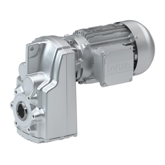
- Page 1 G50BS113 ... G50BS319 g500−S130 ... g500−S19000 | 130 Nm ... 19000 Nm Shaft−mounted helical gearboxes Mounting Instruction Shaft−mounted helical gearboxes with motor...
- Page 2 Please read these instructions before you start working! Follow the enclosed safety instructions. 0Abb. 0Tab. 0...
-
Page 3: Table Of Contents
............Lenze ¯ MA 12.0018 ¯ 4.1... - Page 4 ..........Lenze ¯ MA 12.0018 ¯ 4.1...
-
Page 5: About This Documentation
Qualified skilled personnel are persons who have the required qualifications to carry out all activities involved in installing, mounting, commissioning, and operating the product. Tip! Information and tools concerning the Lenze products can be found in the download area at www.lenze.com Document history... -
Page 6: Conventions Used
Wildcard Wildcard for options, selection data Terminology used Term In the following text used for Gearboxes Gearboxes of the g500 product family Drive system Drive systems with g500 gearboxes and other Lenze drive components Lenze ¯ MA 12.0018 ¯ 4.1... -
Page 7: Notes Used
Reference to a possible danger that may result in property Stop! damage if the corresponding measures are not taken. Application notes Pictograph and signal word Meaning Important note to ensure trouble−free operation Note! Useful tip for easy handling Tip! Reference to another document Lenze ¯ MA 12.0018 ¯ 4.1... -
Page 8: Safety Instructions
... must not be actuated if the drive system shows vibration accelerations > 2g (20m/s ... must not be actuated in the resonance range of a system or the Lenze drive system. ¯ All specifications of the corresponding enclosed documentation must be observed. - Page 9 ¯ check that all component parts with a loose fastening are secured or removed; ¯ tighten all transport aids (eye bolts or support plates). Use an appropriate means of transport and lifting equipment! (¶ 19) Lenze ¯ MA 12.0018 ¯ 4.1...
- Page 10 Corrosion protection Lenze offers paints with different resistance characteristics for drive systems. Since the resistance may be reduced when the paint coat is damaged, defects in paint work (e.g. through transport or assembly) must be removed professionally to reach the required corrosion resistance.
- Page 11 − as specified on the nameplate and in the sales documents. Operation outside the specified temperature range can lead to increased wear and even failure. Disposal Sort individual parts according to their properties. Dispose of them as specified by the current national regulations. Lenze ¯ MA 12.0018 ¯ 4.1...
-
Page 12: Application As Directed
Connections must only be made when the equipment is deenergised and the motor is at standstill. – Installed brakes are no fail−safe brakes. ¯ Dangerous voltages at the power terminals, even if the plug is removed: residual voltage >60 V! Lenze ¯ MA 12.0018 ¯ 4.1... - Page 13 Never disconnect plug when energised! Otherwise, the plug can be destroyed. – Switch off power supply and inhibit controller prior to disconnecting the plug. Fire protection ¯ Fire hazard – Prevent contact with flammable substances. Lenze ¯ MA 12.0018 ¯ 4.1...
-
Page 14: Product Description
¯ The most important technical data is given on the nameplate. ¯ The product catalogues contain further technical data. Short overview of the new mounting positions M1[A] M6[E] M2[D] M5[F] M4[C] M3[B] Fig. 1 Mounting positions: new designation − [old designation] Lenze ¯ MA 12.0018 ¯ 4.1... -
Page 15: Identification
Geared motor with a directly mounted motor (layout B, with QR code) 14.2 14.3 16.1 14.1 16.2 16.4 16.4 16.5 16.5 16.3 33.2 33.1 r/min 20.1 16.7 cos j 16.6 10.2 10.3 Gearbox with motor adapter 10.2 10.3 20.1 Lenze ¯ MA 12.0018 ¯ 4.1... - Page 16 Type of motor / standard Gearbox type Motor type Technical data Ratio Rated torque Rated speed Rated frequency Rated voltage Rated current Maximum current Rated power [kW] Rated power [HP] 5.10 Continuous standstill torque Lenze ¯ MA 12.0018 ¯ 4.1...
- Page 17 C86 = motor code for inverter parameterisation (code 0086) Efficiency class CC number Department of Energy (optional) Permissible ambient temperature (e.g. Ta £ 40°C) Weight Encoder data 33.1 Encoder type 33.2 Encoder voltage Load capacity (specified if c<1.0) Internal key: QR code Lenze ¯ MA 12.0018 ¯ 4.1...
-
Page 18: Gearbox / Geared Motor Product Code
Servo adapter with a jaw coupling with a plug−in hollow shaft ICE adapter with a jaw coupling Servo adapter with a plug−in hollow shaft with a clamping ring without a keyway Lenze ¯ MA 12.0018 ¯ 4.1... -
Page 19: Mechanical Installation
The motors attached to the gearbox are partially equipped with eyebolts. They are exclusively determined for mounting/dismounting the motor to the gearbox and must not be used for the complete geared motor! Fig. 2 Ear for transporting the complete drive system Lenze ¯ MA 12.0018 ¯ 4.1... -
Page 20: Preparation
¯ In some cases, due to lack of space, stud bolts with nuts must be used instead of head screws. In these cases, contact Lenze, if necessary. Tighten all screw connections with the torques given and lock them with standard... -
Page 21: General Information About The Assembly Of Drive Systems
10.9 with correspondingly high tightening torques. – Secure screwed connections with medium strength using screw locking adhesive. Lenze ¯ MA 12.0018 ¯ 4.1... -
Page 22: Gearboxes With Breathers
Gearboxes with breathers Stop! Do not place gearbox onto breather valve! The g500−S130/G50BS113 und g500−S220/G50BS122 gearboxes do not require any ventilation measures. Gearboxes that are delivered with a ventilation unit are provided with a label. Remove the transport locking device on the vent valve before initial commissioning. -
Page 23: Gearbox With Compensation Container (Preferably For Mounting Position "M4[C]")
¯ If the pipe shows any signs of damage, replace it. Note! With unfavourable combinations of a small ratio and a high input speed, the use of a compensation reservoir may also be advisable in other mounting positions. Lenze ¯ MA 12.0018 ¯ 4.1... -
Page 24: Mounting The Gearboxes
Gearbox with output flange ¯ Especially with regard to applications with an alternating load, Lenze recommends...: – the use of anaerobic adhesive between the gearbox flange and mounting area in order to increase the friction fit;... - Page 25 [N] Maximum permissible force F M Tab M Tab 1A/2B −−−−− −−−−− −−−−− −−−−− −−−−− 1500 1500 1500 1500 1500 1500 1500 1500 1500 1500 1500 1500 1500 1700 1700 1700 1700 −−−−− 2600 3500 3500 Lenze ¯ MA 12.0018 ¯ 4.1...
-
Page 26: Mounting Of G500 Short/Servo Adapters With Clamping Connection
DIN 42955 R (reference values for smooth running < 0.025 mm; axial runout and concentricity < 0.05 mm). Fig. 3 Measurement of the surfaces of smooth running, axial runout and concentricity Motor flange Centering Lenze ¯ MA 12.0018 ¯ 4.1... - Page 27 ¯ The drive system must have cooled down. ¯ The motor must be deenergised. Note! Lenze recommends the use of smooth motor shafts without slots! 7. Check: ¯ If the drill depth in the hollow drive shaft is sufficient for the motor shaft.
- Page 28 Removing the plug from the bell housing Gearbox Plug Bell housing 3. Align the slots of the gearbox drive hollow shaft and the clamping ring to each other and to the mounting hole (Fig. 6). Lenze ¯ MA 12.0018 ¯ 4.1...
- Page 29 Mounting of motor and gearbox Gearbox Wrench Motor Stop! If the motor shaft is provided with a keyway, align the motor shaft in such a way that the keyway is located opposite to the terminal screw. Lenze ¯ MA 12.0018 ¯ 4.1...
- Page 30 Maximum permissible load at the motor adapter Note! Lenze recommends the use of smooth motor shafts without slots! 5. Position the motor shaft vertically and centrically to the hollow drive shaft and insert it carefully into the hollow drive shaft. Exert only little force in order to prevent damage to the ball bearing in the bell housing and the motor.
-
Page 31: Mounting Of Motors To Gearboxes With An Adapter And A Flexible Coupling
With higher degrees of protection or when there is a risk of dirt or humidity entering, additionally seal the contact surfaces with a suitable sealant. Fig. 8 Input side design N Spider / gear rim Locking screw Coupling hub Keyway Lenze ¯ MA 12.0018 ¯ 4.1... - Page 32 Tab. 2 Attachment of motors to gearboxes with adapter * Use original featherkey of the motor 1) Featherkey for standard hub and clamping hub 2) Measured from the seating face of the motor flange Lenze ¯ MA 12.0018 ¯ 4.1...
-
Page 33: Coupling Hubs
For this purpose, only use mineral oil−based lubricants without additives, silicone−based lubricants, or vaseline. 5. Align claws of the motor−side coupling hub with its counterpart. 6. Slowly push on motor, and bolt on to the gearbox flange. Lenze ¯ MA 12.0018 ¯ 4.1... - Page 34 For this purpose, only use mineral oil−based lubricants without additives, silicone−based lubricants, or vaseline. 6. Align claws of the motor−side coupling hub with its counterpart. 7. Slowly push on motor, and bolt on to the gearbox flange. Lenze ¯ MA 12.0018 ¯ 4.1...
- Page 35 3. Tighten the screws in the forcing threads crosswise and step−by−step so that the clamping ring is loosened. 4. Clean and grease all contact surfaces including threads and head of the clamping screws before reassembly. Lenze ¯ MA 12.0018 ¯ 4.1...
-
Page 36: Mounting Of Motors To Gearboxes With A Short Adapter With A Plug−In Hollow Shaft With A Keyway (Drive−End Version B Or H)
5. Position the motor shaft centrically to the hollow drive shaft and then insert it into the hollow drive shaft carefully, only exerting little force, in order to avoid damaging the ball bearings in the bell housing and the motor. By no means join Lenze ¯ MA 12.0018 ¯ 4.1... - Page 37 Mounting of motors to gearboxes with a short adapter with a plug−in hollow shaft with a keyway the parts by hammer strokes! 6. Screw the motor and gearbox flange together, securing the fixing screws using medium−strength screw locking adhesive. Lenze ¯ MA 12.0018 ¯ 4.1...
-
Page 38: Attachment Of Gearboxes With Hollow Shafts And Keyway
Take up forces only via the hollow shaft, and not via gearbox housing. 5. Secure the gearbox axially: – The hollow shaft has snap ring grooves for axial securing. Parts used to fix the shaft are not included in the scope of supply. Lenze ¯ MA 12.0018 ¯ 4.1... - Page 39 Mounting of g500 short/servo adapters with clamping connection Attachment of gearboxes with hollow shafts and keyway K12.0611 Auxiliary tool (recommended dimensions) Æ Tab. 3 Dimensions in [mm 6. Cover rotating screw heads, interfering edges, slots or similar items safe against contact. Lenze ¯ MA 12.0018 ¯ 4.1...
- Page 40 53.5 15.8 −−− 54.8 −−− 17.8 −−− 59.8 −−− 64.1 19.8 −−− 69.8 −−− 74.1 21.8 −−− 79.8 −−− 85.1 24.8 −−− 89.8 27.8 −−− 99.8 31.8 −−− 119.8 Tab. 4 Dimensions in mm Lenze ¯ MA 12.0018 ¯ 4.1...
-
Page 41: Mounting The Shrink Disc With A Rotating Cover
¯ Degrease hollow shaft bore and machine shaft! Depending on the design, the shrink discs may be equipped with a rotating cover (pos. Note! This cover is fitted to the shrink disc on delivery. Lenze ¯ MA 12.0018 ¯ 4.1... - Page 42 7. Tighten clamping screws (2) one after the other (see Fig. 14) in several passes, with rising torque, evenly until the indicated screw−tightening torque (see Tab. 6 ) is reached at all screws. GT−GNG−003.iso/dms Fig. 14 Explanation: "one after the other" Lenze ¯ MA 12.0018 ¯ 4.1...
- Page 43 8. Push protective cap (1, Fig. 13) onto the shrink disc. Tip! For finding out the cause of non−reached torques of the shrink disc connection, please go through the troubleshooting list in chapter 8. Lenze ¯ MA 12.0018 ¯ 4.1...
- Page 44 ¯ the connection is spinning due to overload or a too low friction factor and fretting corrosion has occurred, ¯ the shrink disc has been tightened too much leading to a plastic deformation of components, ¯ the components are corroded. Lenze ¯ MA 12.0018 ¯ 4.1...
-
Page 45: Mounting The Fixed Cover
1. Screw reducing bushes (3) into the flange so that they are flush using a screwdriver. 2. Fasten the protective cap (1) over the reducing bushes (3) on the flange using cheese head screws (2). Lenze ¯ MA 12.0018 ¯ 4.1... -
Page 46: Foot Mounting
Aligning the gearbox with the foot: independent of the mounting order, the gearbox must be aligned with the machine shaft. Gearbox Tightening torque Code Type [Nm] G50BS113 + G50BS122 g500−S130 + g500−S220 G50BS140 + G50BS166 g500−S400 + g500−S660 Lenze ¯ MA 12.0018 ¯ 4.1... -
Page 47: Torque Plate Assembly
G50BS221 g500−S2100 2x12 G50BS231 g500−S3100 2x12 G50BS245 g500−S4500 2x12 G50BS280 g500−S8000 G50BS314 g500−S14000 G50BS319 g500−S19000 Note! Solvents, oils, greases, and fuels damage the rubber elements. Be absolutely sure to prevent contact with these substances! Lenze ¯ MA 12.0018 ¯ 4.1... -
Page 48: Electrical Installation
To correctly connect the motor options, e. g. brakes or feedback systems, please observe: ¯ the notes in the corresponding terminal box ¯ the notes in the corresponding operating instructions ¯ the technical data on the corresponding motor nameplate. Lenze ¯ MA 12.0018 ¯ 4.1... -
Page 49: Commissioning And Operation
¯ CLP HC 220 Food−compatible oil ¯ CLP PG 460 USDA H1 Note At an ambient temperature mainly above +30 °C ¯ Application case must be verified by Lenze Low−temperature Ambient temperature −30 °C ... +10 °C Lubricant Food−compatible oil ¯... -
Page 50: Before Switching On
Has the transport locking device been removed? Stop! At input speeds below 200 rpm the amount of lubricant may need to be increased. Consultation with Lenze is required. Initial commissioning In order to ensure trouble−free operation, carry out checks during initial commissioning. -
Page 51: During Operation
¯ In the event of faults: – shut down the drive, – check the troubleshooting table. If the fault cannot be remedied, please contact the Lenze customer service. Lenze ¯ MA 12.0018 ¯ 4.1... -
Page 52: Maintenance
– The lubricant change depends on the lubricant temperature, see Fig. 18. 1. Measure the lubricant temperature at the drain plug, 2. Add 10 °C, 3. Read the changing interval from the diagram. Lenze ¯ MA 12.0018 ¯ 4.1... - Page 53 Replace roller bearing When an oil change is carried out, the roller grease filling bearing grease filling should also be replaced ^ 68 Lenze ¯ MA 12.0018 ¯ 4.1...
-
Page 54: Maintenance Operations
Maintenance operations Maintenance operations Gearboxes and geared motors are ready to use on delivery and filled by Lenze with the lubricant type and lubricant quantity indicated on the nameplate. The first filling corresponds to the mounting position and design indicated on the nameplate. -
Page 55: Position Of The Lubricant Monitoring Elements
Position of the lubricant monitoring elements g500−S130 ... g500−S660 G50BS113 ... G50BS166 Mounting position M1 [A] Mounting position M2 [D] Mounting position M3 [B] G50BS113 G50BS113 G50BS122 G50BS140 G50BS113 G50BS122 Filling Drain Breathing Control Lenze ¯ MA 12.0018 ¯ 4.1... - Page 56 Maintenance Maintenance operations Position of the lubricant monitoring elements Mounting position M4 [C] Mounting position M5 [F] Mounting position M6 [E] G50BS140+ G50BS166 G50BS122 G50BS122 G50BS113 G50BS113 G50BS113 G50BS113 Filling Drain Breathing Control Lenze ¯ MA 12.0018 ¯ 4.1...
- Page 57 Maintenance Maintenance operations Position of the lubricant monitoring elements g500−S950 ... g500−S4500 G50BS195 ... G50BS245 Mounting position M1 [A] Mounting position M2 [D] Mounting position M3 [B] Filling Drain Breathing Control Lenze ¯ MA 12.0018 ¯ 4.1...
- Page 58 Maintenance Maintenance operations Position of the lubricant monitoring elements Mounting position M4 [C] Mounting position M5 [F] Mounting position M6 [E] G50BS231 Filling Drain Breathing Control Lenze ¯ MA 12.0018 ¯ 4.1...
- Page 59 Maintenance Maintenance operations Position of the lubricant monitoring elements g500−S8000 ... g500−S19000 G50BS280 ... G50BS319 Mounting position M1 [A] Mounting position M2 [D] Mounting position M3 [B] Filling Drain 2−stage Breathing Control 3−stage Lenze ¯ MA 12.0018 ¯ 4.1...
- Page 60 Maintenance Maintenance operations Position of the lubricant monitoring elements Mounting position M4 [C] Mounting position M5 [F] Mounting position M6 [E] Filling Drain Breathing Control Lenze ¯ MA 12.0018 ¯ 4.1...
-
Page 61: Table Of Lubricants
In case of ambient temperatures < −20°C or > +40°C, please contact Lenze! Observe increased starting torques at low temperatures! The type of lubricant indicated on the nameplate by the following manufacturers is approved. Shell Klüber Fuchs Lenze ¯ MA 12.0018 ¯ 4.1... -
Page 62: Checking The Oil Level
4 UH1−220 N Shell Shell Omala Shell Omala S2 G 460 S4 GX HD 320 bremer & leguil Cassida Fluid GL 220 7.3.3 Checking the oil level Note! Check the oil level in cold condition! Lenze ¯ MA 12.0018 ¯ 4.1... - Page 63 Maintenance Maintenance operations Checking the oil level Geared motor g500−S130/G50BS113 ... g500−S660/G50BS166 Check the oil level by means of the displayed dipsticks. Manufacture them according to the mounting position. Form template: dipsticks for g500−S130/G50BS113 M1, M4, M5 Lenze ¯ MA 12.0018 ¯ 4.1...
- Page 64 Maintenance Maintenance operations Checking the oil level Form template: dipsticks for g500−S220/G50BS122 Lenze ¯ MA 12.0018 ¯ 4.1...
- Page 65 Maintenance Maintenance operations Checking the oil level Form template: dipsticks for g500−S400/G50BS140 Lenze ¯ MA 12.0018 ¯ 4.1...
- Page 66 Maintenance Maintenance operations Checking the oil level Form template: dipsticks for g500−S660/G50BS166 M1, M6 Lenze ¯ MA 12.0018 ¯ 4.1...
- Page 67 Bleeder screw/oil filler plug Oil−level bore d2 [mm] Filling height x [mm] Tightening torque [Nm] M10 x 1 M12 x 1.5 M16 x 1.5 M20 x 1.5 G 1/8" G 1/4" G 3/8" G 3/4" Lenze ¯ MA 12.0018 ¯ 4.1...
-
Page 68: Changing The Oil
7.3.5 Lubricate roller bearings The roller bearings on motors and gearboxes from Lenze are filled with the greases listed below: Ambient temperature Manufacturer... -
Page 69: Drain Condensation
For horinzontal motor shafts to IP23 and for vertical motor shafts to IP20. Fig. 20 Motor with condensation drain holes Condensation drain holes Repair ¯ We recommend having all repairs carried out by the Lenze Service department. Lenze ¯ MA 12.0018 ¯ 4.1... -
Page 70: Troubleshooting And Fault Elimination
If any malfunctions should occur during operation of the drive system, please check the possible causes using the following table. If the fault cannot be eliminated by one of the listed measures, please contact the Lenze Service. Fault Possible cause... - Page 71 © 03/2021 | MA 12.0018 | .\@Y | 4.1 | TD09 Lenze SE Postfach 101352, 31763 Hameln Hans−Lenze−Straße 1, 31855 Aerzen GERMANY Hannover HRB 204803 Ü +49 5154 82−0 Ø +49 5154 82−2800 Ù sales.de@lenze.com Ú www.lenze.com...
Need help?
Do you have a question about the G50BS113 and is the answer not in the manual?
Questions and answers