
Related Manuals for Lenze Global Drive ERBD R Series


Summary of Contents for Lenze Global Drive ERBD R Series
- Page 1 Show/Hide Bookmarks EDKRBD180R .&B} Montageanleitung Mounting Instructions Instructions de montage Global Drive ERBDxxxRxxxx Bremswiderstand Brake resistor Résistance de freinage...
- Page 2 Show/Hide Bookmarks Lesen Sie zuerst diese Anleitung und die Dokumentation zum Grundgerät, bevor Sie mit den Arbeiten beginnen! Beachten Sie die enthaltenen Sicherheitshinweise. Please read these instructions and the documentation of the basic device before you start working! Observe the safety instructions given therein! Lire le présent fascicule et la documentation relative à...
- Page 3 Show/Hide Bookmarks ERBDECS001...
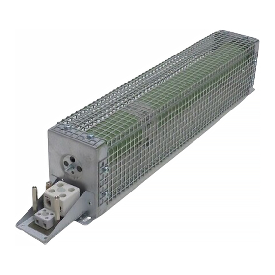
- Page 4 Show/Hide Bookmarks Scope of supply Pos. Description Brake resistor ERBD..Mounting Instructions Brake resistor elements Pos. Description Terminal box Cable gland for brake resistor cable Cable gland for thermal contact cable Fixing bracket Warning note Nameplate Validity These Instructions are valid for brake resistors ERBD..
-
Page 5: Safety Instructions
Show/Hide Bookmarks Safety instructions Safety instructions Danger! The brake resistor can reach a surface temperature of 250 °C. ƒ –Skin contact can cause burns. –A fire hazard exists if flammable objects/materials are placed on the brake resistor or in its vicinity. –The specified mounting position (vertically suspended with terminal box at the bottom) as well as the mounting clearances are to be observed. - Page 6 Show/Hide Bookmarks Safety instructions Definition of notes used Definition of notes used The following signal words and symbols are used in this documentation to indicate dangers and important information: Safety instructions Structure of safety instructions: Danger! (characterises the type and severity of danger) Note (describes the danger and gives information about how to prevent dangerous situations)
- Page 7 Show/Hide Bookmarks Safety instructions Definition of notes used Special safety instructions and application notes for UL and UR Pictograph and signal word Meaning Safety or application note for the operation of a UL-approved device in UL-approved systems. Warnings! Possibly the drive system is not operated in compliance with UL if the corresponding measures are not taken.
-
Page 8: Technical Data
Show/Hide Bookmarks Technical data Technical data Standards Conformity Low-Voltage Directive Approvals UL508, Industrial Control Equipment, Underwriter Laboratories (File-No. E208678) for USA and Canada Operating conditions Permissible ambient -10 °C ... +55 °C operating Above 40 °C the continuous power P is to be reduced by 2.5 %/°C temperature Permissible site... -
Page 9: Mechanical Installation
Show/Hide Bookmarks Mechanical installation Mechanical installation Danger! The brake resistor can reach a surface temperature of 250 °C. ƒ –Skin contact can cause burns. –A fire hazard exists if flammable objects/materials are placed on the brake resistor or in its vicinity. –The specified mounting position (vertically suspended with terminal box at the bottom) as well as the mounting clearances are to be observed. - Page 10 Show/Hide Bookmarks Mechanical installation Dimensions Dimensions ERBDECS003 All dimensions in millimetres Type [mm] ERBD180R300W 439 ±3 ERBD100R600W 639 ±3 ERBD082R600W 639 ±3 EDKRBD180R DE/EN/FR 2.0...
- Page 11 Show/Hide Bookmarks Mechanical installation Dimensions ERBDECS004 All dimensions in millimetres Type [mm] ERBD068R800W 539 ±3 ERBD047R01K2 639 ±3 ERBD018R01K6 639 ±3 EDKRBD180R DE/EN/FR 2.0...
- Page 12 Show/Hide Bookmarks Mechanical installation Dimensions ERBDECS005 All dimensions in millimetres Type [mm] ERBD033R02K0 639 ±3 EDKRBD180R DE/EN/FR 2.0...
- Page 13 Show/Hide Bookmarks Mechanical installation Dimensions ERBDECS006 All dimensions in millimetres Type Type [mm] ERBD018R03K0 739 ±3 ERBD022R03K0 739 ±3 EDKRBD180R DE/EN/FR 2.0...
- Page 14 Show/Hide Bookmarks Mechanical installation Dimensions ERBDECS007 All dimensions in millimetres Type [mm] ERBD015R04K0 639 ±3 EDKRBD180R DE/EN/FR 2.0...
- Page 15 Show/Hide Bookmarks Mechanical installation Dimensions ERBDECS008 All dimensions in millimetres Type Type [mm] ERBD018R06K0 739 ±3 EDKRBD180R DE/EN/FR 2.0...
- Page 16 Show/Hide Bookmarks Mechanical installation Mounting steps Mounting steps How to mount the brake resistor: 1. Select a suitable mounting location. – Mounting position vertically suspended with terminal box at the bottom – Observe mounting clearances! – Flammable materials may not be placed in the vicinity of the brake resistor.
-
Page 17: Electrical Installation
Show/Hide Bookmarks Electrical installation Connection data Electrical installation Connection data Cable gland Cable gland Connection cross-sections Tightening torque [AWG] [Nm] [lb-in] T1, T2 (thermal 0.25 ... 4 24 ... 12 0.6 ... 0.8 5.3 ... 7.1 contact) RB1, RB2 0.5 ... 10 20 ... - Page 18 Show/Hide Bookmarks Electrical installation Mounting steps How to connect the brake resistor: 1. Undo the two screws at the terminal box and remove cover . 2. Connect brake resistor cable: – Use shielded cables (2 cores + PE; the PE connection must comply with EN 50178).
Need help?
Do you have a question about the Global Drive ERBD R Series and is the answer not in the manual?
Questions and answers