
Related Manuals for Lenze SX-1


Summary of Contents for Lenze SX-1
- Page 1 Lenze Antriebstechnik Operating instructions Manual for positioning system SX-1 programmIng termmal PT.1...
- Page 2 09.05.1994...
-
Page 3: Table Of Contents
1. Contents _Page Contents Index General Information Introduction Positioning System SX-1 3.1.1 Layout oftheSX-1 3.1.2 Technical Data for the SX-1 Userlerminal PT-1 3.2.1 Layout of the PT-1 3.2.2 Display 3.2.3 Keyboard 3.2.4 Technical Data for the PT-1 3/11 SX-1 Operating Modes... - Page 4 5.4.3 Analog Output (Ref.) & Analog Input (Override) 5/26 5.4.4 Main Power Suppiy 5/26 5.4.5 External 24V DC Supply 5/26 5.4.6 General Rules 5/26 lnterconnection of SX-1 and Servocirive 5/27 Startup Procedure Startup Structure 6.1.1 Diagnostic Methods 6.1.2 Test Mode Operation Modes of Operation Software Version 5.XX 6.2.1 Modes of Operation...
- Page 5 _____________________________ < __________________________ Page UserKeyCodes 11/1 Instruction List (Version 5.10 January 1989) 12/1 Calling and Operating the Menus 13/1 ECL Gommand Structure Lenze...
-
Page 6: Index
Controller command not altowed sequential program f 10w) Crawling contact 5/19 AF (Automatic mode; single step) Current line 3/11 Ambient temperature PT-1 Cursor Ambient temperature SX-1 Cut-into-Iength-device 10/1 Analog input (override) (Application example) Analog output 5/9, 7/5 Anti-interterence 5/26 DEC (eleration) - Page 7 Feed endless or absolute 8/23 7/22 Inserting a program Feedback Connector 8/22 Installation Feedback interface X4 3/1,3/3 lnterconnection 01 SX-1, Feedback 01 absolute encoder 5/15 5/27 servo amplifier and drive Feedback 01 position-measure- 3/1, 5/13, Interface for incremental encoder ment...
- Page 8 5/14 Material handling 10/7 Max a (Maximum acceleration) Max V (Maximum vebocity) Meaning ot parameters Microprocessor PT-1 3/11 Microprocessor SX-1 Missing relerence pulse MODE Modes 01 operation 3/6, 4/1 Mounting SX-1 3/1, 5/1-2 MOV (-e Irom EEP ROM to RAM)
- Page 9 Page Page Pl. P2 Ratings PT-1 3/11 P3, P4, PS, P6 Ratings SX-1 Reactive bad 5/26 P9, P1O, Ph Ready for work 5/10 P12, P13 Reasonableness check 7/32 Reduction gear P14, P15, P16, P17, P18 7/10 (Setting of reference P19, P20...
- Page 10 Start up procedures 6i 1 Velocity out of bounds 7/32 Start up structure Ventilation Status Sto p 3/8, 3/10, Stop sequence f 10w 6/4, 6/7 Stop single-step Stop switch El/i Elli Storage temperature PT-1 Sto rage temperature SX-1 Structure of programs Lenze...
- Page 11 — ______ Page WAIT 3/8, 8/2, 8/10 Watchdog Weight PT-1 3/11 Weight SX-1 Working temperature PT-1 3/11 Working temperature SX-1 3/1-2, 5/4, 5/7 3/1-3, 5/6, 5/9 3/1,3/3, 4/2, 5/12, 3/1, 3/3, 5/13 Lenze...
- Page 12 Lenze...
-
Page 13: General Information
3. General Information 3.0 Introduction The SX-1 Positioning System allows the precise positioning of workpiece, tool or material, with optimum control of speed and acceleration. Multi-axis Systems may be configured SX-1 using a personal computer, by interconnecting units using the I/O facilities built in. -
Page 14: Positioning System
3-3.1.1 3.1 Positioning System SX-1 SX-1 3.1.1 Layout of the Mountlng holes LED Green: b.s. Bus 5 Reset: resets the controller Metal case select Ax.Nr: Red: Ventilation louvres defines axis number. w.d.: Watch Updated Status by Power On or Dog (error) - Page 15 3.1.2 3.1.2 Technical Data for the SX-1 Weight 3,5 kg Environmental Temperature Operating (Up to 55 0C with forced ventilation) -20 0 +70 0C Storage Humidity 10 ... 90% relative humidity, non-condensing Supply AG 110/220V, +10%, -15%; 50/60 Hz Power Consumption...
- Page 16 ___________—__ 3.1.2 _____- Serial Interface X3 RS 422 link for Program Input and parameter entry from PT-1 or for DNC up to 64 SX-1 may be operated on this bus Measuring System Interface X4 Incremental Encoder Interface with complementary inputs Supply provided 5 V at 200 mA maximum.
- Page 17 • Test Mode: enables movement of the drives without position feedback • Control Mode: set outputs, read inputs for start-up and test functions The PT-1 Terminal is normally supplied with power trum the SX-1 connection. However, it may be operated „ofiline“ from a 24 V DC supply (see Chapter 5.3.3) —...
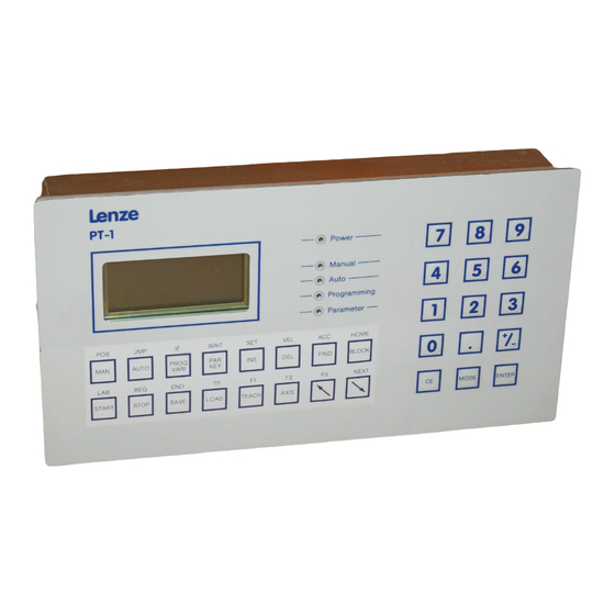
- Page 18 3.2.1 3.2.1 Layout of the PT-1 • • 5L]555[]55 5L]555555 Rear View (Reduced Seale) 6 Numeric Keyboard, with Membrane front panel 4 LED „Power On‘. Ready additional special keys tor operation ha Metalcase Connectorforthe 5 LED Mode display: serial link to the SX-h 4 Lines and 2 LCD Display MANUAL...
-
Page 19: Display
3.2.2 —__——_______ 3.22 Display Operating mode Working Area Columns: The display is of 4 Lines by 16 Line 1: Operating mode Lines 2-4: Working Area, i. e. Input of Program lnstructions, Parameter Data, Variable values, Actual Position display, etc. Example of Display ANUAL-EXT Gurrent Axis Number ____... -
Page 20: Keyboard
3.2.3 3.2.3 Keyboard The PT-1 has a Membrane Keyboard with two areas: a Function keyboard and a Nume- ric keyboard with additional special keys. The Function Keyboard The keyboard legend can be changed by inserting an „Underlay“ in the slot a the lett ofthe keyboard. - Page 21 Start Start program execution STOP Stop Stop program execution SAVE Save Save program or parameters from PT-1 to SX-1 Load program or parameters from LOAD Load SX-1 to PT-1 TEACH Teach The release of the changeable desired posi and the transfer in the program...
- Page 22 Numeric keys. In some modes these have special meanings Plus/Minus (or direction) „Glear Entry“ or „Correct Error“: if pressed before ENTER, the entry is discarded Prepares tor data/text entry, or moves the cursor MODE The instruction or data is entered into memory ENTER ____ — —--—--- Lenze...
- Page 23 3.2.3 The User Keyboard „Underlay“ Symbol M ean Ing Select Manual Mode Remote __________________ Auto matic Mode Select Variable Data Entry Key Code Number Manual-Remote Reference (Home) — —— Start Auto-Remote Stop 3/10 Lanze...
- Page 24 4 Lines by 16 Columns LCD Alpha-Numeric Display Display 5 LEDs for display of mode 15 keys tor Numeric and speelal functions Keyboard 16 keys tor operating mode seleetion and programming RE; 485 (422) for connection of up to 64 SX-1 Interface 3/11 —____ ________ Lanze...
-
Page 25: Operating Modes
4. SX-1 Operating Modes Over View (For detailed information, refer to Chapter 6 „General Operation“) The SX-1 has different operating modes for starting the axis control, verifying program- ming, and diagnosing and correcting errors. There are three ways of operating the SX-1: •... -
Page 26: Manual-Remote Mode
4.1-4.3 4.1 Remote Control In the Remote modes, the control signais are provided via the Serial Interface Connector X3. You may use either the PT-1 Terminal, or a Host Computer (either an Industrial Computer or a PC). There are extra instruetions tor DNC Operation. There are two modes of Remote Operation: „Manual-Remote“... -
Page 27: Manual-Remote Operation
4.4 Manual-Remote Operation The following menues select Manual-Remote Operation V4.X V5.X Mode selection switches E5 E6 E7 E8 E5 E6 E7 E8 E9 E1O Eh 1011 „REMOTE“ Menu: LED „MANUAL“ illuminated Manual-Re mote Manual-Remote > < lncremental Mode Distance Mode Menu selection: (Jog Mode) _—>... - Page 28 Operating in the selected menu Two Speeds: Slow: 5 Fast: F Continuous Jog Toggle SPEED with on Nume- Manual-Remote ric keypad < ACTUAL POS ± xxxxx.xx] Jog in two directions (Function keyboard) Incremental Jog Toggle DIRECTION with Manual-Remote + AOO Numeric keypad Select the distance with the appro- 1=0,001...
- Page 29 — ____ Manual-Remote Display: > < Incremental Mode Distance Mode Note: To quit the Distance Mode, it is sometimes necessary to press ENTER to terminate number entry. Selecting another Menu: PROG VARI corresponding to the inscription next to the LED‘s. ____ Lanze...
- Page 30 Lenze...
-
Page 31: Installation
5-5.1 5. Installation 5.1 Dimensions, Mounting, and Ventilation ½ Attention! When installing, ensure that the upper and lower ventilation louvres are not obstructed. A 50 mm clearance is required at the top and Ihe bottom. Avoid ~t< :=~tS*~&&~.t%~&i‘9 »~ lanze... - Page 32 of fixing screws <—80 —* 5 mm maximum 5Omm clearence 5Omm clearence Attention! Avoud obstructing the upper and lower ventilation gratings. At the top and at the bottom there should be a minimum spacing of 50 mm. Between two control uflits SX-... there should be a minimum spacing of 10 mm /corresponding to adistance of 80 mm between the mounting screws.
-
Page 33: Power Supply Voltage
5.2 Power Supply Voltage board (AX-1) or the SX-1: The external supply is connected at the bottom of the case (SX-1) PT-1: The supply is normally derived from the SX-1 Axis Controller Lanze... -
Page 34: Interface Gonneotions
5.3.1 Interface Connections Parallel Connector Xl (lnputs/Outputs) V5.XX 5.3.1 Functions tor Software Version V5.XX SX-1 nput Input START/STOP mode MANUAL mode AUTOMATIC 0,•— • mode REMOTE 1 001, manual LEFT 1 002, manual RIGHT • 1 003, manual HOME 1 004, manual Feedhokl •... - Page 35 5.3.1 Parallel Connector Xl way D-Sub Functions for Software Version 5.XX pin 1 Input E5 pin 2 Input E6 pin 3 Input E7 Control and Function pin 4 Input E8 pin 5 Input E9 1 001 1 001 1 004 are pin 6 Input E1O 1 002...
- Page 36 5.3.1 Explanation of Connections: • Use inputs E05 E12 (pins 1-8) to select mode and function (see Chapter 6.2) lnputs E09 to E12 may be used as 1001 1004 application program. in the • lnputs El 3 El 6 (pins 9-12) are used as 1 005 to 1 008 in the application program. •...
-
Page 37: Parallel Connector Xl (Inputs/Outputs) V4
5.3.1. 5.3.1 Parallel Connector Xl (Inputs/Outputs) V4.XX Mw~ual EXIERNAL Manuai RIGHT Manuai RIOHT fast Manuai LEFT 1 Meriuai LEFT fasl ~om~to EXIERNAL Siart SINGLE STEP Slop SINGLE STEP Siart CONTINUOUS ~ ~ REMOTE 5topCONTINUQUS shleldlng ~ranumnItted by ..—‚—— mtaiized Setting the modes of operation Softwareversion 4 XX Lanze... - Page 38 El 6 (pins 5-1 2) are used as 1 001 to 1 008 program. • lnputs in the application • Outputs AOl A08 (pins 14-21) are used as 0 001 to 0 008 in the application pro- 9 ram. Lenze...
-
Page 39: Drive Control Gonneotor X2
5.3.2 5.3.2 Drive Control Connector X2 SX-1/21 as „H“-signat <El olosing) EI =servo enabte n“disturbance resot“ by present error; error acknowledge by fauling edge at El Screw connector Exiernal supply Servo Power On Enable MC/Reset error Negative end of travel... - Page 40 Servo Enable Contact •Pin 6-7; This contact can be opened or closed to enable the servo. lt is operated by the SX-1 when there is an Enable input (pin 2) and a positive result tor internal checks. lt there is a fault concerning the Operation of the position loop (enable fault, Encoder error), then this output is cancelled.
- Page 41 5.3.2 Servo Power On • Pin When the input is active, the Controller is enabled and the Reference signal is acti- vated at zero until takes place. When the input is not active, the control movement automatically terminates the movement. Servo Power ON Input at X2 pin 10 is used for instant interruption of the program and movement.
-
Page 42: Serial Interface X3 (Pt-1 Connection)
(RS 485, RS 422) pin 6 Not used pin7 Not used pin 8 Power Supply to PT-1 pin 9 Signal Ground (RS 485, RS 422) SX-1/21 X1I 15 way D-submale nterface n.c. TxD-<RS 485) TxD+ RxD- 0V SIgnal graund n.c. - Page 43 5.3.4 5.3.4 Incremental Encoder Connection X4 D-Sub, Male (Encoder Module FB-1) 9 pin pin 1 pin 2 pin 3 +SVsupply 0 V supply pin 6 pin 8 Control ~ pin 9 ConneCt pin 8 to pin 4 if no „Lamp Control“ connection is provided at the encoder. SX.1/21 Incrmmntal .ncod.r!
- Page 44 4 0 V Supply pin 5 pin 6 not used pin 7 not used U Supply not used SX-1/21 Absolute encoder with encoder module FB-2/1 0 Inc rementalencoder n.c. n.c. n.c. Isolate encOder and coupling is transmitted...
- Page 45 5.3.4/1 Parallel Interface 5.3.4/1 Option: 1/0 Expansion EA-4 EA-4 Conneotor 32 way F-type plug z28__ lnputs user programmable 1 min zl 8 DC 20-33V t in 10 ms zl 6 zl 4 El 0 z12__ zl 0 El 2 ________________ El 3 ________________ all In-/Outputs...
- Page 46 Option: I/O Expansion EA-4 DIP Switch for I/O Card Coding Front panel EA-4 pc-board EA-4 DIP Switch S1 for card code selection Binary coded see table on the next page! LED-Display tor In-/Output power supply input 24V externai lnputlOutput Connector 32 5/16 Lenze...
- Page 47 In the appliCation program the inputs and outputs are divided into module groups and addressed as follows: Group 0 are SX-1 I/O 1 008, 0 001 0008) (1 001 Group 1 are first EA-4 I/O (1101...
-
Page 48: Internal Adjustements
5.3.5 5.3.5 SX-1 Internal Adjustments The SX-1 may be adapted forvarious operating conditions by Internat coding switches and jumpers (links). For the location ofthe switches and jumpers on the card, see the diagram at the end of this section <page 5/22). - Page 49 ‚~.3.5 Switch S3 Configuration Selection of principal modes and hardware configuration. Position feedback selected by Encoder Module Relerence Flag output on A8 0ff: Analog Input selected by Encoder Module. (Jumper J1) on: MODE 0 (Normal mode) off: MODE Addressing) 1 (Internal Axis Delivery state SW~&V on W~...
- Page 50 Drive Enable and NC Ready outputs Enable and NC Ready may be set tor active high and active 10w. This for Drive be altered on the SX-1 card by Jumpers J9, JIO and J1 1, • Seleotion for Drive Enable Jumper open Drive Enable active „L“...
- Page 51 5.3.5 Seleotion of other Jumpers Warning! The following jumpers must not be disturbed. Their setting is given only to allow checking and correction of unintentional change. If they are changed, then normally the controller will not function. J1 External System Clock Jumper standard (open from Slave axis)
-
Page 52: Axis Controller Module
5.3.5 • Axis Controller Module SX-1/21 ~‚C • IInI.r> •~r~IJ,~ UL...J... ‚6 06L~ ~ 1~ — LIO“d — ~0‘~ ________________ _________ ‚6 ß,0‘6 ‚6‘6 ~001 —~ ‚6 _______________________ r~-~,--—~ ‚00 Ii liii UII —~ ‚..‚ __________________________ DO~ ~ ~jnnn‘~ .4-,- •... - Page 53 5.3.5 • Axis Controller Module SX-1/21 Installation Front panel of SX-1 Mother-board of axis controller SX-1 Encoder module Plug-in module FB-1 incremental Plug-in module FB-2 absolute Install carefully!! connector X4/ SX-1 5/23 Lanze...
- Page 54 5.3.5 • Encoder Module FB-1 (Incremental) Component Layout LII c2J5J4 INKREMENTAL 1.‘ EtOSt.O 5187 c2,c6 ...„R2Bft27R3C0 R24 ft13 ft47J1 -iii 9<STUECKUNaSDfiUCK El OSt .0 Encod.r module FB1/FB2 FB-1. incremental feedback module J2 instailed: Impulse multiplier x4 Factory installed • • •...
-
Page 55: Encoder Module Fb-2 (Absolute)
5.3.5 • Encoder Module FB-2 (Absolute) 7 ~Io 52f::Lfi1 Component Layout L~LbUL LJ LJ — LL130R12 0 EZZI OLr~ ~‚ BESLJECL<UNGSORUCK EL0~2 2 2588 Plug-In module for F62 FB-2, absolute feedback module ~nstalled A/D canverler activel Warning 1 AID converter ic AD 574 must be installed with pin 1 of IC on pin 1 of the socket (See drawing) -
Page 56: Main Power Suppiy
________________ 5,4 Protective Measures and lnterference (Nolse) Avoidance All lnputs and Outputs of the SX-1 <excepting the Analog Input and Output) are isolated the internal bus. For added security, you must take from following precautions: Encoder Cable 5.4.1 The cable should be in shielded and twisted pairs for eaCh Channel, and of sufficient Cross section to avoid voltage drops. -
Page 57: Lnterconnection Of Sx-1 And Servocirive
Servodrive (Suggested) Before interconnecting the SX-1 and the Servodrive, you must consider the following ite ms: • The servo drive should be selected to suit the bad. • The Emergency Stop circuit should be checked for correct Operation. - Page 58 Lanze...
-
Page 59: Startup Procedure
The separation ot Parameter setting and Programming offers great system flexibility. For example, the Parameters may be set by the machine builder, whilst the Program is set by its user. Also, the SX-1 can save several user programs at one time, e.g. to allow the handling of difterent parts or operations. -
Page 60: Diagnostic Methods
Output Number: 0001 Input Number: 1 607 In the left-hand display, the SX-1 outputs 0001 to 0 008 are shown. The cursor is on the position 0 001. The lnputs to the SX-1 are shown in the sequence 11,1 2,1 3,1 4, first 1 5,1 6,1 7, 1 8, E 1, E 2, E 3, E 4, E 5, E 6, E 7, E 8. -
Page 61: Test Mode Operation
6.1.2 ____ 6.1.2 Test Mode Operation The test mode is provided for use during commissioning and for servicing and trouble- shooting. The operati ng mode is pre-selected by Parameter P24 =0, but this is not operable after the control is reset. until NOTE: After the test session, then P24 must be set to a non-zero value. -
Page 62: Modes Of Operation
Control is from the PT-1 or EPAS, using the serial communication link. The Manual, Home, Automatic and Continuous modes are available. This mode is selected by input E8. SX-1 displays „d“ on the 7-segment display. Input ES High continuesthe program, and ES starts and stopsthe movement of the axis: ES interrupts the program. - Page 63 Automatic (Start) Remote If more than one operation mode is selected at one time, an error El 2 (Mode Double- Selected) is shown on SX-1. Input E5 is read dynamically for Start function, and statically for the supervisory func- tion. All movement are interrupted by opening E5 and resumed by closing E5.
-
Page 64: Modes Of Operation Software Version
Input ES is read dynamically tor the „start“ function, and statically tor the supervisory function. b) Homing is initiated by the 0-1 edge at E7, and E7 is monitored statically during the homing cycle. c) Input ES is monitored statically as the supervisory function. ___— — — —___ Lenze... - Page 65 —_______________ Notes Remote Mode Program execution is monitored using input ES: program execution is interrupted if this contact is opened; movement is stopped at maximum deceleration. When ES is re-activated, the remaining distance is firsttravelled, and then program execution is continued. Notes Manual External Software V 4..00...
- Page 66 lanze...
-
Page 67: Parameters
7.1.1 Parameters Parameters and their meaning at a glance 7.1.1 The Parameters Axis Parameter Number of Name of Meaning Parameter Parameter Program Number Resol Resolution 1.000 to 9999.999 lncrements/Unit lncrements per Revolution 1 .. .10,000 VoNm Analog Voltage to Speed Ratio Tscan Scanning rate 3 to 30 ms Max V... - Page 68 7.1.1 Control Parameters Number Name Meaning of Par. of Par. HomM Homing Mode 0...5 P 26 Hom V Homing Velocity: 0.1 to 6000.0 units per sec. P 27 Hom N Homing necessary for position control YES/NO? ACceleration Charactenstic LIN/SIN 2 P 28 Ramp P 29...
-
Page 69: Meaning Of Parameters
7.1.2 Meaning of Parameters To assist understanding of the following descriptions, we show here a simple example of a servo axis using a toothed (timing) belt drive. Load Mass (kg) Friction force (N) Pulley: diameter d (mm) Reducition gear (x:1) lnertia Jrefl (kg.m 2) *) Maximum motor speed nmax (rpm) Jmotor (kg.m2) - Page 70 For Absolute Encoder: (1/rev) (1/rev) . iv • 1/rev. Pulses per revolution Pulse multiplier in SX-1 (1, 2 or 4; Standard: 4) Reducer ratio — Feed constant (Units/Revolution at gearbox output) Resol.iTurn Resolution/ Revolution tor multi- or single turn absolute encoder.
- Page 71 P3: Analog Voltage to Speed Ratio (Vo/Vm) [ratio The value entered is the ratio of the speed used to the nominal speed multiplied by the reference voltage tor nominal speed. •Vin Units: Ratio Range: 0.1 to 9.9 Nrated maximum motor speed maximum speed used Nused reference for maximum speed...
- Page 72 7.1.2 Vmax Vmax maximum velocity of the drive acceleration time The values for Vmax and the aCceleration time may be read from the velocity diagram for the application. Vmax urne P6 — Mdbes • Motor Load 2K•i ‚&~~x‘~ Mdbes Permissible accelerating torque (Nm) Moment of Inertia of the motor (kgm 2) Motor = Moment of lnertia of the bad (kgm2)
- Page 73 7.1.2 —__________ ___________ P7: Manual slQwjog speeci(MAN S Units/~L _____ Units tor P7: Distance Units per second. Upper limit: Vmax (see PS) This value determines the slow Jog speed in the manual modes. P8: Manual fast jog speed (MAN F) [Units/s _____ Units tor P8: Distance Units per second.
- Page 74 This is used to shift the zero point with respect to the Home position tor programmed movements. The software limit switches P9 and Pl 0 always refer to the true zero (Home) position. Offset zero po• t Pl 1 Home Position (Reference Null Point) Lenze...
- Page 75 7.1.2 P12: Sign of Analog Servo Output (S SIGN) P13: Sign of Position Feedback (E SIGN) Possible values: „Normal“, „Inverse“ The direction parameters 5 SIGN and E SIGN are usedto invertthe sign of the Servooutput and the Encoder Feedback (for forward or reverse motion). Two forms of reversal are possible: NOTE! 1.
- Page 76 ~IQ7.1.2 P14: Backlash Correction Positive direction (Tool +) P15: Backlash Correction Negative direction (Tool Units: Distance Units +99999.999 Range of Values: P14: PiS: ~...-99999.999 With these parameters you may correct tor tool offset or lost motion (backlash) during positioning. With absolute positioning in the positive direction, you move towards the destination less the amount of P14, and in the negative direotion less the amount in P15.
- Page 77 7.1.2 Coupling of the bad to the Servo System The numerical control SX-l produces acontrol signal that is dependent upon the differen- ce between the Required Position W and the Actual Position X. This signal causes a movement in such a direction as to reduce that difference. Thus the difference between Required and Actual position (W becomes zero when (W X) =0, and the servo...
- Page 78 P19, P20: Switch point output (KP1, KP2) The SX-1 provides tacility for 3 position loop gains, set by the parameters. This allows optimum use ot the full acceleration capability ot the drive up to torque limits, and at the same time prevents over-driving the control should an excessive acceleration parameter be entered.
- Page 79 7.1.2 KV-factor and Gain Break points in general The aim of each positioning movement is: 1. To have as small a difference between the Required and Actual positions as possible, e. to reach final position as quickly as possible. 2. To reach the required position with high accuracy. You can achieve both aims by using a high value of KV.
- Page 80 However, this algorithm would take muCh time to calculate, and the acCuracy, stability and stiffness would not be greatly improved over the SX-1 algorithm, which selects one of three different KV values, according to speed.
- Page 81 7.1.2 R. p. m. Velocity Reference Voltage Vref: thus voltage can be used to define the Gain Break points for the KV tactors. —KVO — — —> Max V Programmed values ot KP1 and KP2 The Gain Break point voltages are the values where the corresponding KV values change. NOTE: The KV values and Break Point voltages are normally set by expenenced servo engineers at the machine supplier, and should NOT be changed by...
- Page 82 7.1.2 P21: Following Error Tolerance (E Lim Units: % Values: 12.5, 25, 50, 100, 200, 500 The Following Error is the difference between the required and actual position. The Tolerance or Limit is the permitted deviation from the theoretical value as a percentage. (Vmax) 100%= •16.667...
- Page 83 7.1.2 internal Position reached /‚ position window r~1t~ Ä Set point output Time out konstant sec. Time-out supervision If tinal positioning time exceeds 1 second, error E 16 is displayed. Positioning time-out is reported if the position window is not reached within the Time-out period. HINTS: Check KV-values Check drive operation...
- Page 84 7.1.2 ____ P23: Integration Factor (I-Fct.) Unit: and Correction Interval (defined by code number) The position controller is of the Proportional type: it is possible to introduce an Integral term by detining this code number. Standard va~ue: 0 The code number has three digits: Percentage l-factor code Multiple ot Scan ning Rate P4, when I-factor is added.
- Page 85 _______________________ 7.1.2 P24: Mode of Operation Normal mode ot operation: P24 non-zero. Test mode is selected when P24 Attentlon! This mode is only used tor installation and commissioning. See Chapter 6.1.2. 7/19 ____ Lanze...
- Page 86 7.1.2 P25: Homing Mode (Horn M) Versions: 0 lt you are using an incremental position feedbaCk system, it is normally necessary to initialize the distance measuring system afterswitch-on, if absolute positioning is required. This is done by „Homing“ or „Referencing“: Six methods are available: Version 0: Drive in positive direction to Reference SwitCh: then go to zero (marker) pulse ot the...
- Page 87 Version 3: As Version 2, but with reversed direotions. End of Travel Switch Reference Switch zero pulse of encoder Version 4: Here, the Reterence Switch is closedupto the Negative Limit Switch. lt thissignal is active, the drive goes in the positive direotion to the talling edge, and then tinds the firstzero pulse thereafter.
- Page 88 7.1.2 P27: Homing Necessary? (Horn N) Possible: Yes or No This Parameter is used to select whether or not the start of automatic program operation is dependent on first having Homed. No (homing not necessary): program starts in any event. Acceleration Characteristic Linear or Sin 2 P28: (Ramp)
- Page 89 7.1.2 The defined mode of acceleration is used tor all positioning. Important notes regarding Sin 2 mode 1. If Sin2 mode is selected, it is not possible to use position instructions with change- over ot velocity, e. g. PA Vdd V. 2.
- Page 90 With the Variable Data menu, variable values may be changed, and when correct, sentto the SX-1 by pressing the ENTER key. lt several axes are connected to the PT-1, then normally only the selected axis is supplied with data. lt you wish to supply data in parallel to several SX-1 controls, then use Parameter P31.
- Page 91 7.1.2 Example: snortest shortest route: route: clockwise anti- 1000 clockwise Definition of variables Some program instructions may be performed either with directly-specified values, or with indirectly-specified values by using variables (see Chapter 8). Examples of programming with direct values: 40.000 PA 6000.000 Examples of programming with indirect values, using variables: PR VOO1...
- Page 92 7.1.2 (N-V~) P33: Name of Variable ~ Up to 6 characters may be entered: Example: Speed Details ot Entry: See Chapter 7.2 P34: Format of Variable ~ (F-V~O) The MODE key selects the following formats: torvelocity, acceleration, deceleration (in for counter values (increments) and delay periods (ms) xxxxx for velocities in direct values, e.
-
Page 93: Parameter Entry And Variable Definition
7.2 Parameter Entry and Variable Definition To enter Parameters, proceed as tollows: 1. Connect the PT-l terminal to the SX-1 via communications link (PT-l ceives power from SX-l). j~ij;~ 1 AC 220V Now the PT-1 is, tor example, in the „Auto- PT 1 External“... - Page 94 ______ 2. Press the PAR/KEY key: the PROGRAMMING and PARAMETER Key: LED‘s should light together. The PT-1 expects the entry ot a code numberto permit entry of Parameters (see Chapter 12). P~ TYP. ~ H-14... Pgm# 3. Input code numbers and press ENTER. PROGRAMMING LED goes out;...
- Page 95 6. Select the next parameter with the arrow key. Pl INC/UNIT Pgm# Resol 5.5555 IPR\ The contents of ihe LCD display scrolls up a line. Line Contents of working line: number of selected parameter units tor parameter to be entered lncr/U Line Previous parameter (here...
- Page 96 Use the arrow keys to move the cursorto the required character, and press ENTER toselect. This character will then appear in the tirst position ot the name. NV~~ xxxxxx xABCDEFGH Cu rsor~~ characters are selected and The next five the same way. After all six entered in characters are entered, the name is dis- played, and the previous and next...
- Page 97 The parameters are first stored in the memory otthe PT-l. Pressing the SAVE keytransmits them into the EEPROM memory ot the SX-l tor preservation despite supply interruption. Do not forget to do this! The values may be sent even when a program but they are not then used until is running, the program is stopped, because a short conversion routine must be performed.
-
Page 98: Changing Parameters
7.3 Changing Parameters Firstly, you must select PARAMETER mode (see Chapter 7.2). 2. Load the parameters to be changed trom the SX-1 into the PT-1 usirig the LOAD key. This copies the parameters trom the SX-1 into the PT-1 memory. -
Page 99: Parameter Limits
7.4 Parameter Limits Limits of Ranges for Ski On entering Parameters, the allowable limits may be exceeded. In the first line of the PT-1 display, the following reports may appear: limit exceeded limit not reached KV out ot range gain factor incremental velocity too high calculation of tollowing error out of range speed... - Page 100 tanze...
-
Page 101: Programming
ECL programming language. Main programs can be broken up into subroutines: the SX-1 can have up to 20 main Programs, each with up to 100 subroutines. lt is possible to „nest“ subroutines up to 10 deep. Subroutines are „called“ using JMP (jump) instructions: when the END ot a Subroutine is reached, the Program continues at the calling JMP ruction. -
Page 102: Program Lnstructions
8.2 Program Instructions 8.2.1 Overview A tew often sufficient to build a complex and understandable program instructions are The tollowing instruction groups are available: program. • Organisation the program): instructions (for structuring detining the begining and end of main programs and subroutines conditional and unconditional jumps branch conditions for building... -
Page 103: Programming Lnstwctions And Their Meaning
8.22 Programming lnstructions and their meaning BEG Hnnnnnn, END Hnnnnnn Meaning: Beginning and End ot Main program. Input: BEG, ENTER, number, ENTER 999 999 Number ot the Program H: nnnnnn BEG Uww, END Uww Meaning: Beginning and End ot Subroutine. Input: BEG, MODE, ENTER, numbers, ENTER Number ot Subroutine U: ww Label Lww... - Page 104 L=LOW(=O) Numberotlnputsl: xxx =1.6.16 NumberotLabelL: ww=0...99 IF lxxx H Uww IF lxxx L Uww Meaning: Subroutine Uww, it 1 xxx Jump to input either H HIGH (=1) L=LOW(=O) Numberotlnputsl: xxx=1...6.16 Number ot Subroutine U: ww ... 99 —~________________ ___________ Lenze...
- Page 105 —_____________________ 8.2.2 ______ lFFvv=H Lww lFFvv= LLww Meaning: Jump to Label Lww (Address ww), it Flag Fvv is eitherH HIGH (=1) L=LOW(=~I) Number ot Flag F: ... 99 Number of Label L: ww ... 99 A number ot Flags are reserved as tollows, and must not be used tor other purposes: motion F99=H;...
- Page 106 This position instruction refers to the home (zero) position of the machine. NOTE: second lt two absolute position instructions with the same value follow each other, the instruction causes no turther motion. Example: PA 1000.000 PA 1000.000 no effect .~— ____ _________— Lenze...
- Page 107 8.2.2 PR vvvvv.vvv Meaning: Move the distance vvvvv.vvv relative to the present position Value: vvvvv.vvv -99999.999 ... +99999.999 This position instruction relates motion to the present (actual) position of the machine, rather than to the home (Zero) position. NOTE: If two relative position instructions with the same value tollow each other, the second instruction causes a second movement ot the same distance as the tirst.
- Page 108 When this instruction, the program is continued immediately, without waiting for reaching the completion otthe positioning. Thus during a positioning movement, inputs ortlags may be monitored and used tor further control. Example: PA 100.OOOC L02 IF F99 L,LO1 IF 101 = L, L02 During positioning to 100.000, Flag F99 and Input 101 are monitored.
- Page 109 8.2.2 ________ _______ _______— -___ ____ ____ HOME _____ Meaning: Initiate the Homing cycle. VEL ccc VEL Vddd % Meaning; value. Seleot Velocity VEL) directly (ccc) or by variable (Vddd) as a ot maximum 100% Value: ccc= 1 Variable number V: ddd 0000.0 VELVddd Meaning:...
- Page 110 8.2.2 _______ _____ DEC ccc DEC Vddd% ____ ____________ Meaning: of Deceleration rates. Entered by Variable (Vdd) as a % maxi- Selection directly (ccc) or mum. Value: ccc=1...100% Variable number V: ddd Note: When using 51n 2 acceleration mode, this value is irrelevant, because acceleration and deceleration are the same.
- Page 111 8.2.2 --__ _____ SET Cvv yyyy SET Cvv Vddd Meani ng: Preset Counter Cw to value yyyy or to the value ot Variable Vddd. Number ot Counter C: vv ... 99 Counter value yyyy -9999 to +9999 Variable number: ddd 255.
- Page 112 8.2.2 V Ihe given text (up to 12 characters) is displayed on the PT-1. (Only in „Auto“ Meaning: mode). Application: For Status and Diagnostic display on the PT-1, Example: TXT: GOMMENT 8/12 Lenze...
- Page 113 8.2.~) lyyy. Fvv SET Oxxx Meaning: Set Output Oxxx to the Boolean AND function ot Input lyyy and Flag Fvv. 0.01 6.16 Number ot Output yyy= 0.01 6.16 Number ot Input 1: Number ot Flag F: 0...99 SETOxxx=Iyyy+ Fvv Meaning: Set Output Oxxx to the Boolean OR function ot Input lyyy and Flag Fw.
- Page 114 8.2.2 — SET Oxxx • Meaning: Set Output Oxxx to the Boolean AND tunction ot Flag Fvv and Flag Fww. NumberotOutputO: xxx =0.01 6.16 Number of Flag F: NumberofFlag F: ww =0... 99 SET Oxxx Meaning: Set Output Oxxx to the Boolean OR function ot Flag Fvv and Flag Fww. Number of Output 0: xxx 0.01 ...6.16 NumberofFlagF:...
- Page 115 8.2.2w lxxx. lyyy SET Fvv Meaning: Set Flag Fw to the Boolean AND function ot Input lxxx and Input lyyy. NumberotFlagF:w =0...99 Number ot Input 1: xxx 0.01 6.16 6.16 Numberotlnputl:yyy=0.01 SET Fvv lxxx lyyy Meaning: Set Flag Fw to the Boolean OR tunction ot Input lxxx and Input lyyy. F:vv=0...99 Number ot Flag Number ot Input...
- Page 116 Ihe result ot the division ot Veee by Vtff is saved Vddd. Variable number V: ddd Variable number V: eee Variable number V: Veee Vddd Meaning: Variable Vddd is set equal to Veee. Variable number V: dd d= 0 Variable number V: eee 8/16 Lenze...
- Page 117 8.2.2 _____________________________— SKVddd vvvvv.vvv Meaning: Add the value vvvvv.vvv to the present value ot Vddd. Variable number V: ddd ... 255 -99999.999 Value vvvvv +99999.999 IF Vddd Veee Lvv > Meaning: lt Variable Vddd is greater than Variable Veee, then continue Program at Label Lvv. V:ddd=0...255 Variable number Variable number V: eee...
- Page 118 8.2.2 MOV Vddd EEPROM -> Meaning: Variable Vddd is saved in LEPROM. Variable number V: ddd Meaning: MOVEEPROM ->RAM All variables which are in RAM are over-written with values from FEPROM. PA vvvvv.vvv DP Meani ng: the shortest With a circularaxis, or endless belt drive route to an absolute position is used.
- Page 119 8.2.2 ________________________________- Vddd = ISTPOS M ean ing: The present Actual position is saved in Variable Vddd. Variable number V: ddd +ppppp.ppp Meaning: During a positioning movement, an external signal (TP Touch Probe) is anticipated. After the appearance of this signal, the distance +ppppp.ppp is covered. NOTE: lt sin 2 acceleration is selected, the TP signal is accepted only when constant velocity is If aTP input is receivedduring acceleration ordeceleration, then Flag F95 is set.
- Page 120 8.2.2 < Vddd Meaning: Ihe PTP Vddd instruction, in contrast with the PTP Vddd W Veee instruction, specities no „window“ torthe positioning distance. This means that after the start of positioning, the first TP the TP input is not received, the Flag F96 is set. signal is awaited.
- Page 121 Status: H Touch Probe whilst Accelerating or Decelerating in ~in 2mode. Status: H Touch Probe not recognized. Status: H Homed. Status: H Acceleration mode: Status: 1-1 sin2 linear Drive in motion Status: H 8/21 __________ ____ _________-- — ___________ Lenze...
-
Page 122: Program Entry
Ihis is displayed on the LCD display and corre- sponding on the PT-1, and on the 7-segment display of the SX-1. 2.Press PAR/KEY key. Ihe PROGRAMMING and PARAME- KEY: 1ER LED‘s light together. Ihe PT-1 awaits the entry ot the Code number „key“... - Page 123 ____ Type in the code number: tinish with P~ (TYP. ENTER. H-V14 Pgm# Resol. The PROGRAMMING LED is extinguished, and remains on. PARAMETER 5. Press the PROG key. The menu Edit shown at the side appears. Position MODE key, accor- the cursor with the Erase ding to whether you wish to Edit a Pro-...
- Page 124 When entering the Program instructions, you should in use the tollowing general sequence ot keystrokes: instruction is displayed (e. g. from group of 1. Press the required instruction key, similar instruction, group), but in this casethe „Wait“ e.g. WAll without values. Here, example, the MODE key is pressed...
- Page 125 0ff immediately. EDIT (A Program in the PT1 may be edited) NEW POM (Enter a new Program) (Erase/Delete a Program) DELETE PGM (The Directory ot all Programs in the SX-1 is displayed) LIST OF PGM‘s Scroll with the arrow-keys 8/25 Lanze...
- Page 126 Erase Listof PGMs Ihe main menu is again displayed: BIk: 27 M: Ihe first line of the selected program 22.4 V displayed. F IND Searoh forthe required Instruction/ Block number Soroll through Ihe instruction numbers. 8/26 -______ ______ _______ Lenze...
- Page 127 Completion of Program Entry 1. After the last instruction ot a new or Blk: 16 M: edited entered, press Program is PR + 22.3~I ENTER once more. 17.2~I WAIT lOms iO (~s ~L) This message is displayed brietly (the Pro- gram is checked tor syntax errors: it any are tound, they are displayed in normal text), and then the main menu...
- Page 128 PT-1 is deleted, and the BEG(inning) and END instruction ot the new Program appear. BLK:~ M: M OOO~3 M ~O~O3 See the beginning ot this chapter tor details. turther 8/28 ______ ______ _____ ______-- Lenze...
- Page 129 ____ Erase PGM lt the main menu is displayed, select ERASE PGM on the third line by using the MODE key to move the cursor to it. Commence with ENTER: Erase ____ PgmNo The Program to be deleted is requested. Enterthe numberand press ENTER.
- Page 130 DELETE ________________ Pressing this key deletes the instruction at working line 3. INSERT When this key is used, the instruction in working line 3 is scrolled up, and a space is inser- ted after it, indicated with a“>“ symbol. The empty line is maintained after every instruction is entered, so that several instructions may be entered in succession.
-
Page 131: Entry Of Variable Data
______ 8.4 Entry of Variable Data lt is always possible to enter or change data in those Variables which have been selected and named during Parameter entry. A code key number is not required. The entry ot Variable data is initiated as tollows: a) lt a key code number has not yet been entered, press PROGNAR key. - Page 132 ______ 6. Enterwith: Hint: lt an entry is (too small or too large), then it is brietly displayed and the invalid ‚~ entry ignored. The Variable data are only held in the butter memory, and must be re-entered when the control is switched on again.
-
Page 133: Display And Editing Variable Values
Display and Editing Variable Values After entering Variable values, they are immediately saved to the SX-1 (without pres- sing SAVE). Variable values may also be changed whilst the Program is running: a) by the user b) trom the Program itselt. A display ot the current values is possible by pressing the PROGNAR key. -
Page 134: Selecting And Running A Program
Automatic Remote Mode In this mode, it is possible to use the PT-1 to select a Program trom an archive ot up to 20 Programs in the SX-1 controller, and to control it using the tunction keys. El LIII Program Number... - Page 135 Program number selection and choice ot Single Step (S-ST) or Continuous (Auto) running mode may only be pertormed >P_ <FS when a Program is not running. First choose a Program number. Move the cursor to P using the MODE key, press ENTER, and the old Program AR->P_ number is deleted.
-
Page 136: Axis Ldentification
Please enquire tor intormation. Axis ldentification When the SX-1 is Switched On or Reset, an Axis ldentification number is displayed. Example: Sequential display of Axis~ 8.9 Software ldentification When the SX-1 is Switched On or Reset, a Software ldentitication number is displayed after the Axis ldentification. -
Page 137: Error Messages And Correction
7-Segment display of the SX-1 and on the arising error PT-1. The SX-1 sequentially displays the error by a letter „E“ tollowed by a 2-digit number. The tollowing errors are possible: Error Meaning Possible Cause and... - Page 138 Change Program System set to Endless mode: does not allow Absolute positioninci Only in version 5.X modes selected! Two operating Change Program Ouput not present Check coding switch Mode selection incorrect Home Home position no found Position window, KV value too Excessive positioning time small Check Program...
- Page 139 Slave lncorrect information whilst Internal error interpolating, in Master Parameters missing; Error After initiating a SAVE-tunc when Saving Parameters or tion, the SX-1 must remain Programs switched on tor sufticient time to ensure safe programming ot the EEPROM Lanze...
- Page 140 Parameter data read upon switch-on. They can be resulting corrected only by the entry ot new or corrected Parameters. when SX-1 is executing a Program, or being manually operated. b) Errors arising is stopped. The error may be cancelled by positive edge on Input Program execution El (Enable SX-1).
-
Page 141: Application Examples
Application Examples 10.1 Cut-off line (Shear) Shear up Shear down Start A d.c. motor feeds sheet metal trom a coil through a pair ot rollers to the Shear. The metal sheet must be cut oft to the specitied length. Program BEG MOQOQOl Start ot main program 1 Wait tor Start signal... - Page 142 be as tollowing: The program could BEG MOOOOO1 WAIT 101 VEL % VOO Velocity is detined by Variable VOO. ACC 100 DEC 100% PRVO1— cut-ott length is detined by SETOO1 =H Variable VOl. WAIT 101 = H SETOO1 =L WAIT 103 JMP LOO END HOOOOO1 ability to change the length ot the sheets and the line...
-
Page 143: Transfer Unit
10.. 10.2 Transfer Unit 200mm —~ A hole is to be drilled in aworkpiece. Theretore the unit must traverse dose tothe workpiece at high speed, then move at teed-speed tordrilling. lt must tinally traverse back to the start position. During drilling, a check tor drill breakage takes place: it this occurs, it must stop immediately and return to the start position. - Page 144 Program BEG MOOOOO1 Start ot main program 1 WAIT 101 Wait tor Start edge WAIT 101 = H SETOO2= L Reset „Ready“ signal PA 200.000 V Traverse to 200 mm/continue at 10 % PA 350.000 C Feed to 350 mm and continue program IF F99 L, LOl...
-
Page 145: Bottling And Weighing Machine
10.3 Bottling and Weighing Machine DC Servodrive Material Metering screw, e. g. 1 revolution Scales Ihe material is ted into its container using a metering screw. The amount ot material is proportional to the movement ot the screw, which is positioned with a Servomotor. To correct tor density variations in the material, a sample is weighed every 100 tillings, and the amount is corrected tor over- or under-weight. - Page 146 Program BEG M000004 1000.000 SET VOO Set Variable VOO 1000.000 SETCOO=0 Set Counter COO WAIT 101 Wait tor Start Meter 1000.000 g ± correction PR VOO SETCOO=C+ 1 IF COO> 100 LOl lt counter> 100 then weigh sample Return to Start JMP LOO Activate Scales L0 1...
-
Page 147: Material Transfer
10.4 Material Transfer Pallet Exchanger (Transfer) A transfer loop has several workstations, which operate on the workpieces. The required workstation tor each workpiece is detined by 3 (binary-coded) The NC system inputs. should select the shortest direction to take to the workstation. 10/7 Lanze... - Page 148 10.. Program BEG MOOOOO1 WAIT 104 Wait tor Start signal WAIT 104 Read input value and assign to Counter 000 JMP SOl IF 000 Position 1 IF 000 Position 2 IF COO Position 3 IF 000 Position 4 IF COO Position S IF 000 Position 6...
- Page 149 BEG S02 Generate „Read“ signal SEIQOl =H Impulse Output 001 tor 500 ms WAll 500 ms SETOO1 =L 10/9 Lanze...
- Page 150 Lanze...
- Page 151 11. User Key Codes To enter a Program or Parameters, a code number must tirst be entered by selecting „Parameter“ on the PT-1, whereupon „KEY“ appears. Depending on which Parameters you wish to edit or enter, you must use the appropriate key.
- Page 152 Lanze...
- Page 153 12. Instructions (Version 5.10 January 1989) lnstruction Meaning Memory Used BEG Hnnnnnn Start of Main Program nnnnnn BEG Uww Start ot Subroutine ww End of Main Program nnnnnn END Hnnnnnn End ot Subroutine ww END Uww Home sequence HOME VELccc% Velocity preset to 1-100% Velocity preset in Units/second 0000.0...
- Page 154 PA Vddd C Position Absolute and Continue by Variable PR Vddd C Position Relative and Continue by Variable LRvvvvv.vvv Mhh Linear interpolation Relative ot Master with Slave hh Linear interpolation Relative ot Slave Rwvvv.vvvS LRvvvvv.vvvST Linear interpolation Relative ot Slave Tvvvvv.vvv with turning point (e.
- Page 155 — —____ ____ lxxx*Fww Set Flag uu Input xxx AND Flag ww SET Fuu lxxx Set Flag uu Input xxx OR Flag ww SET Fuu lxxx*lyyy Set Flag uu Input xxx AND Input yyy lxxx Set Flag uu Input xxx OR Input yyy SET Fuu lyyy SET Fuu...
- Page 156 vvvvv.vvv Luu Jump to Label uu it Position Actual Position > > IF.< vvvvv.vvv Luu Jump to Label uu if Position Actual Position < Jump to Label uu it Position Actual Position > Vddd > IF c Vddd Luu Jump to Label uu it Position <Actual Position IF Vddd>...
- Page 157 Calling and Operating the Menus Summary Manual control from „Programming“ Menu PT-1 Calling a Menu Selecting part of Menu Entering selected parts Working with selected item Activation ot basic com- Details: mands See Chapter 4.4 Activate commands with Enter required data PT-1, possibly tunction key pad.
- Page 158 inspection and Parameter Run and Control changing, Variable decla-ET1 w425 75 ESEl of Program Menu ratio n „AUTO-REMOTE“ „PARAMETER“ Activate Menu Key number, and Enter Menu or part ot Menu Choose AUTO/Step [E]EE] Start Program execution Working in Menu A~~..Parameter with with and complete entry ot Para- meter number with...
- Page 159 Run and Control Parameter inspection and of Program Menu changlng „AUTO-REMOTE“ „PARAMETER“ Complete data entry with „ENTER“ key. Exit with Exit from Menu You may stop You may complete data entry with „ENTER“ key; programming Activate another Menu. Activate another Menu 13/3 Lanze...
- Page 160 Lanze...
- Page 161 ECL Command Structure Command Memory Used BEG Hnnnnnn BEG Uww f5~n~7777I7I77IZ7j [ENDUww HOME HOME VELccc% VEL 00000 U/s VELVddd % VEL Vddd U/s ACC ccc % DEC ccc ACC Vddd % DEC Vddd % JMP Lww JMP Uww WAll bbbb ms WA lT WAIT lxxx = H WAlTIxxx=L...
- Page 162 Command Used Memory PA vvvw.vvv PA vvvvv.vvv VEND = ccc % PR vvvvv.wv PR vvvvv.vvv VEND = ccc % PA vwvv.vvv C PR vvvvv.vvv C STOP PA Vddd PA Vddd VEL = Veee PR Vddd PR Vddd VEL = Veee PA Vddd C PR Vddd C LR vvvvv.vvv Mhh...
- Page 163 Memory Used Command SETOxxx=L SET Oxxx = H SETFww=L SETFww=H SET Cww = aaaa SET Cww = C + aaaa SET Oxxx = lyyy & Fuu SET Oxxx = lyyy 1 Fuu SET Oxxx lyyy & lzzz SET Oxxx = lyyy 1 lzzz SET Oxxx = Fww &...
- Page 164 Memory Used Command SET SOLL = ISTPOS SETP=Vddd MCV Vddd -> EEPROM MCV EEP ROM -> VAR IF lxxx = H Uww IF lxxx = L Uww IF lxxx = H Lww IF lxxx = L Lww IF Fuu = H Uww IF Fuu = L Uww IF Fuu = H Lww IF Fuu = L Lww...
- Page 165 Number from -99999.999 to +99999.999 ppppp.ppp Number from 0 to +99999.999 gggggggg Number from -99999999 to +99999999 ttttitittitt 12 ASCII Signs greater than less than equal to plus minus multiplied witht divided by & logical AND iogical OR Lenze...
- Page 166 — 4‘. 4PNta <‚Str • — Head Office 1 Mechanical Drives Lenze GmbH & Co KG Estertal Postfach i2 50, 0-32696 Esrertat Sitz: Bosingfeid, Brestauer Straße 3 0-32699 Eztertal 2 (05262) 401-0, Telex 931 526 Te etes 5262 8i0 teefas...
- Page 167 (Ot) 9441212 Japan Teles 826107, Telefax (01) 9441233 Bareac de Wisse Rcmenoe Pcllay Co. Ltd. 13141 46t lmal-Minami-Cno, Nakahara-Kc Lenze Bachofen S.A Granids Cnsmps 4 J-Kawaaakl-01t4 (044) 733- 51sf, Telex 03842110 1033 Cnexeaux s.L Telefax (044)7112431, 733124t lt (021) 7310212...
- Page 168 Lenze GmbH & Co KG Aerzert Postfach 10 1352, D-31 763 Hameln, Sitz; Groß Betel, Hano-Lenze-Stral3e 1, D-31 855 Aarzen 5< 54< 62-0. Telex 92 653, Te(etex 51 54 11, Telefax (0 51 54) 4040 Telefon Taonnioal elleiations re¶ieiveo Printed in Germany...
Need help?
Do you have a question about the SX-1 and is the answer not in the manual?
Questions and answers