Lenze g500-S Manual
Mains-operated geared motors
Hide thumbs
Also See for g500-S:
- Manual (160 pages) ,
- Project planning (108 pages) ,
- Mounting and switch-on instructions (76 pages)

Related Manuals for Lenze g500-S


Summary of Contents for Lenze g500-S
- Page 1 Project planning EN Mains-operated geared motors g500-S shaft-mounted helical geared motor / Smart Motor m300-E...
-
Page 3: Table Of Contents
Contents Contents About this document Document description Further documents Notations and conventions Product information Product description Identification of the products Features The modular system Designs Mounting positions Information on project planning Safety instructions Basic safety instructions Application as directed Residual hazards Drive dimensioning Final configuration Surface and corrosion protection... - Page 4 Contents Product extensions Torque plates Shaft covers Motor connection Connection via terminal box Connection via QUICKON V2 connector Connection via M15 connector Connection via M12 connector Brakes Spring-applied holding brake Brake resistors Accessories NFC adapter QUICKON connector UMCLN_SGG_100181 Product codes Motor data Rated data Ecodesign Directive...
-
Page 5: About This Document
The documentation must always be complete and in a perfectly readable state. • Further documents Information and tools with regard to the Lenze products can be found on the Internet: www.Lenze.com à Downloads... -
Page 6: Notations And Conventions
About this document Notations and conventions Notations and conventions Conventions are used in this document to distinguish between different types of information. Numeric notation Decimal separator Point Generally shown as a decimal point. Example: 1 234.56 Warnings UL Warnings Are used in English and French. UR warnings Text Engineering Tools... -
Page 7: Product Information
This led to a large number of different drive variants.. Things are different with the Lenze Smart Products: Due to the possibility of freely adjusting the motor speed within a fivefold adjustment range at a constant torque, very different speeds can be enabled with one single drive variants. - Page 8 Only an NFC-capable Android smartphone or the Lenze NFC adapter for PCs is needed as a tool. The data can therefore be read and written when the drive is in a de-energised state –...
- Page 9 Contactor and motor protection functions integrated The Lenze Smart Products can be started and stopped by mean of digital inputs. It is also possible to switch between different speeds and rotating directions. Up to 5 different speed modes (e.
-
Page 10: Identification Of The Products
Product information Identification of the products Application examples Roller conveyors with belt ejector Belt conveyors Identification of the products Gearbox product name Gearbox type Product series Type Rated torque Nm Product g500-S130 g500-S220 g500-S400 g500-S660 Shaft-mounted helical g500 gearbox g500-S950 2100 g500-S2100 3100... -
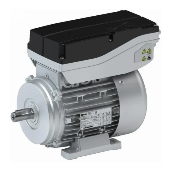
Page 11: Features
Product information Features Features The following figure provides an overview of the elements and connections on the product. Their position, size and appearance may vary. Ventilation (depending on the mounting position) Oil filler plug (depending on the mounting position) Remove oil control plug (depending on the mounting position) Torque support Output flange... -
Page 12: The Modular System
Product information The modular system The modular system Values printed in bold are standard designs. Values that are not printed in bold are potential extensions, some of them including a surcharge. - Page 13 Product information The modular system Geared motors up to 660 Nm Gearbox g500-S130 g500-S220 g500-S400 g500-S660 Min. motor assignment MSEMA□□ 063-42 063-42 063-42 063-42 Max. motor assignment MSEMA□□ 080-32 080-32 080-32 080-32 Technical data Max. output torque Min. drive torque 1.75 1.75 1.75...
- Page 14 Product information The modular system Geared motors from 950 Nm to 4500 Nm Gearbox g500-S950 g500-S2100 g500-S3100 g500-S4500 Min. motor assignment MSEMA□□ 063-42 063-42 063-42 063-42 Max. motor assignment MSEMA□□ 080-32 080-32 080-32 080-32 Technical data Max. output torque 2100 3100 4500 Min.
-
Page 15: Designs
Product information The modular system Designs Designs Gearbox designs Observe the available gearbox designs! 4The modular system ^ 12 g500-S130 ... S660 Hollow shaft, with foot Without centring (HBR) Hollow shaft, without foot Without centring (HDR) With centering (HCR) Flange with through holes (HCK) - Page 16 Product information The modular system Designs Shrink disc, without foot Without centring (SDR) With centring (SCR) Flange with through holes (SCK) Solid shaft, with foot Without centring (VBR) Solid shaft, without foot Without centring (VDR) With centering (VCR) Flange with through holes (VCK)
- Page 17 Product information The modular system Designs g500-S950 ... S4500 Hollow shaft, with foot Without centring (HBR) With centring (HAR) Flange with through holes (HAK) Shrink disc, with foot Without centring (SBR) With centring (SAR) Flange with through holes (SAK) Solid shaft, with foot Without centring (VBR) With centring (VAR) Flange with through holes (VAK)
-
Page 18: Mounting Positions
Product information The modular system Mounting positions Mounting positions Details of the mounting position are needed to ensure the corresponding lubricant amount, position of the ventilation, oil checks and oil drain plug on the gearbox. To reduce the number of different versions, the following gearboxes can also be ordered with combined mounting positions: g500-S130 ... - Page 19 Product information The modular system Mounting positions Position of the terminal boxes Positions of the connections Mains connection Control terminal Cable gland for terminal box M12 connector QUICKON V2 connector M15 connector Position of the manual release lever...
- Page 20 Product information The modular system Mounting positions Position of the hollow shaft with shrink disc The output flange is only available in position "F". Output flange and shrink disc are not possible in the same position.
-
Page 21: Information On Project Planning
Information on project planning Safety instructions Basic safety instructions Information on project planning Safety instructions Basic safety instructions Disregarding the following basic safety instructions and safety information may lead to severe personal injury and damage to property! Only use the product as directed. •... -
Page 22: Residual Hazards
Information on project planning Safety instructions Residual hazards Residual hazards Even if notes given are taken into consideration and protective measures are implemented, the occurrence of residual risks cannot be fully prevented. The user must take the residual hazards mentioned into consideration in the risk assessment for his/her machine/system. - Page 23 Information on project planning Safety instructions Residual hazards Gearbox protection Excessive vibration accelerations and resonances will damage the gearbox. • Do not operate the gearbox at vibration accelerations > 2 g (20 m/s ) of the machine. Do not operate the gearbox in the resonance range of the machine. Excessive torques will damage the gearboxes.
-
Page 24: Drive Dimensioning
With the «Drive Solution Designer«, you can design the drive both quickly and to a high quality. The software contains profound and proven expertise with regard to drive applications and mechatronic drive components. Please get in touch with your Lenze representative. Mains operation Check operating conditions... - Page 25 Information on project planning Drive dimensioning Determine correction factor Ambient temperature °C ≤ 40 Correction factor Installation height amsl ≤ 1000 m ≤ 2000 m ≤ 3000 m ≤ 4000 m Correction factor 0.95 Determine product on the basis of the forces Transmission element Gear wheels Sprockets...
-
Page 26: Final Configuration
STOP: 0 rpm Output speed 2 [500/i ... 2600/i] rpm CW rotation: > 0 rpm Output speed 3 Lenze Smart Motor with gearbox: The ratio i is Output speed 4 taken into account when calculating the output Output speed 5 speed. -
Page 27: Surface And Corrosion Protection
Information on project planning Final configuration Surface and corrosion protection Direction of rotation of the output shaft The direction of rotation of the output shaft is defined by the setpoint of the output speed. The direction of rotation is changed when a positive (n > 0) or negative (n < 0) speed is specified. -
Page 28: Lubricants
Information on project planning Final configuration Lubricants Lubricants The following gearboxes are lubricated for life: g500-S130 • Recommended lubricants: Lubricant CLP 220 CLP 460 CLP HC 220 CLP HC 320 Ambient temperature 0 … +40 °C -30 … +40 °C -20 …... -
Page 29: Ventilation
Information on project planning Final configuration Ventilation Ventilation No venting measures are required for the g500-S130 … S220 gearboxes. The g500-S220 gearbox can optionally be equipped with a breather element. From g500-S400 onwards, the gearboxes are supplied with breather elements as standard. - Page 30 Information on project planning Final configuration Ventilation g500-S220 ... S660 Mounting position M1 (A) Mounting position M2 (D) Mounting position M3 (B) Filling and ventilation ② Check ③ Drain ② g500-S220 ② g500-S400 ③...
- Page 31 Information on project planning Final configuration Ventilation Mounting position M4 (C) Mounting position M5 (F) Mounting position M6 (E) Filling and ventilation ③④ ② Check ② Drain g500-S220 ② g500-S400 ③ g500-S660 ④...
- Page 32 Information on project planning Final configuration Ventilation g500-S950 ... S4500 Mounting position M1 (A) Mounting position M2 (D) Mounting position M3 (B) Filling and ventilation Check Drain...
- Page 33 Information on project planning Final configuration Ventilation Mounting position M4 (C) Mounting position M5 (F) Mounting position M6 (E) Filling and ventilation Check ⑤ Drain g500-S3100 ⑤ Gearbox with oil compensation reservoir for mounting position M4 (C) In order to guarantee a reliable lubrication of the toothed parts in mounting position M4 (C) (motor is on the gearbox vertical from the top), a high filling level is required in the gearbox.
- Page 34 Information on project planning Final configuration Ventilation Dimensions of the oil compensation reservoir For the following gearboxes in mounting position M4 (C), which exceed the specified min. input speed, an oil expansion reservoir is required depending on the specified gear ratio: g500-S2100 g500-S3100 g500-S4500...
-
Page 35: Information On Mechanical Installation
• nameplate and in this documentation. Ambient media − especially chemically aggressive ones − may damage shaft sealing rings, • lacquers and plastics. Lenze offers special surface and corrosion protection in this case. • Transport Ensure appropriate handling. • Make sure that all component parts are securely mounted. Secure or remove loose •... -
Page 36: Information On Electrical Installation
Information on electrical installation Important notes Information on electrical installation Important notes DANGER! Risk of injury and risk of burns from dangerous voltage Power terminals may also carry voltage in the switched-off state or when the motor is stopped and may cause life-threatening cardiac arrhythmia and serious burns. ▶... -
Page 37: Connection According To En
Information on electrical installation Connection according to EN Connection according to EN The following data is valid for a three-phase mains connection with 400 V. Mains connection with QUICKON connector Motor MSEMA☐☐063-42 MSEMA☐☐080-32 Connection Laying system Connection type QUICKON connector Cable type Flexible Cable cross-section... - Page 38 Information on electrical installation Connection according to EN Single drive connection according to EN IEC 60204−1 3/N/PE AC 400/480 V SELV/PELV F1 … F3 F1 … F3 DC 24 V (+19.2 … +28.8 V) max. 50 mA n. c. L2 L3 Rb1 Rb2 L2 L3 Rb1 Rb2...
- Page 39 Information on electrical installation Connection according to EN Group drive connection according to EN IEC 60204−1 F1 … F3 PE L1 L2 L3 PE L1 L2 L3 PE L1 L2 L3 PE L1 L2 L3 PE L1 L2 L3 Max. total rated mains currents at 40 °C for different cable cross-sections Cable installation in accordance EN IEC 60204−1...
-
Page 40: Connection According To Culus
Information on electrical installation Connection according to cULus Connection according to cULus The following data is valid for a three-phase mains connection with 480 V. Mains connection with QUICKON connector Motor MSEMA☐☐063-42 MSEMA☐☐080-32 Connection Connection type QUICKON connector Cable cross-section Typ. - Page 41 Information on electrical installation Connection according to cULus WARNING! ▶ UL marking ▶ Use 75 °C copper wire only, except for control circuits. ▶ Maximum conductor size is AWG14. ▶ Cord connected drives are for use only in NFPA 79 applications. ▶...
- Page 42 Information on electrical installation Connection according to cULus Fuse data (F1 ... F3) Motor MSEMA☐☐063-42 MSEMA☐☐080-32 Cable installation in accordance NFPA 70, NFPA 79 with Fuse Standard UL 248 Typ. Rated current Max. rated current Semiconductor fuse Standard UL 248 Typ.
- Page 43 Information on electrical installation Connection according to cULus Max. total rated mains currents at 40 °C for different cable cross-sections Cable installation in accordance NFPA 70, NFPA 79 with Main cable Cable cross-section Stub Cable cross-section Fuse Typ. Rated current Max.
-
Page 44: Technical Data
The ratings apply to the operating mode S1 (acc. to EN 60034-1). • NOTICE In case of other operating conditions, the achievable values can differ for those mentioned. ▶ In case of extreme operating conditions, please get in touch with your Lenze representative. -
Page 45: Standards And Operating Conditions
The Electrical Equipment (Safety) Regulations 2016 S.I. 2021/745 The Ecodesign for Energy-Related Products and Energy Information Regulations 2021 Approvals GB Standard 12350-2009 For USA and Canada (requirements of the CSA 22.2 No.14) Industrial Control Equipment, Lenze File cULus UL 61800-5-1 No. E132659... -
Page 46: Protection Of Persons And Device Protection
Technical data Standards and operating conditions Protection of persons and device protection Protection of persons and device protection Degree of protection EN IEC 60529,EN IEC Information applies to the mounted and ready- IP55 60034-5 for-use state Type 12 NEMA NEMA 250 Type 4 indoor only Depending on the configuration Insulation resistance... -
Page 47: Environmental Conditions
Technical data Standards and operating conditions Environmental conditions Environmental conditions Climate 1K3 (-30 ... +60°C) <3 months Storage EN 60721-3-1:1997 1K3 (-30 ... +40 °C) >3 months Transport EN 60721-3-2:1997 2K3 (-30 ...+70 °C) EN 60721-3-3:1995 + Operation 3K3 (-30 ...+40 °C) Operation A2:1997 Site altitude... -
Page 48: Radial Forces And Axial Forces
Technical data Radial forces and axial forces Radial forces and axial forces Permissible radial force The calculation of the permissible radial force must take account of the additional load factor rad, perm rad,max Permissible axial force If there is no radial force, the maximum axial force is 50% of the value in the table F rad,max = 0.5 x F ax, zul... - Page 49 1.3 and an input speed of 1400 rpm. In case of different operating conditions, considerably higher forces can be transmitted. Please get in touch with your Lenze representative A hollow shaft with shrink disc (SAR/SBR/SCR/SDR/SAK/SCK) requires a check by Lenze.
-
Page 50: Selection Tables
Technical data Selection tables Selection tables Notes on the selection tables The selection tables represent the available combinations of gearbox, number of stages, ratio and motor for the mounting position M1. They only serve as a rough overview. The following legend shows the layout of the selection tables: Example Explanation = 7.0 Nm... - Page 51 Technical data Selection tables 7 Nm Mains operation Geared motor Min. output speed Max. output speed Starting torque a, 1 a, 2 kgcm² 25.0 24.9 5.263 3.661 g500-S130 MSEMA□□063-42 99.6 34.0 34.1 4.587 5.021 g500-S130 MSEMA□□063-42 78.0 11.0 11.0 44.0 43.5 5.276 6.411...
- Page 52 Technical data Selection tables Mains operation Geared motor Min. output speed Max. output speed Starting torque a, 1 a, 2 kgcm² 98.0 44.8 98.0 3.748 57.933 g500-S130 MSEMA□□063-42 99.0 44.4 99.0 3.767 58.486 g500-S220 MSEMA□□063-42 43.6 3.831 59.581 g500-S220 MSEMA□□063-42 40.7 3.970 63.817...
- Page 53 Technical data Selection tables Mains operation Geared motor Min. output speed Max. output speed Starting torque a, 1 a, 2 kgcm² 1701 1871 3.970 279.807 g500-S2100 MSEMA□□063-42 3.726 280.500 g500-S660 MSEMA□□063-42 1802 1982 3.991 296.430 g500-S3100 MSEMA□□063-42 3.714 300.479 g500-S400 MSEMA□□063-42 1624 1786...
- Page 54 Technical data Selection tables Mains operation Geared motor Min. output speed Max. output speed Starting torque a, 1 a, 2 kgcm² 2350 2350 2050 2255 3.797 1426.741 g500-S2100 MSEMA□□063-42 2418 2418 3100 3410 3.854 1467.835 g500-S3100 MSEMA□□063-42 2483 2483 4500 4950 3.867 1507.081 g500-S4500...
- Page 55 Technical data Selection tables 20 Nm Mains operation Geared motor Min. output speed Max. output speed Starting torque a, 1 a, 2 kgcm² 16.0 16.0 65.0 64.8 31.160 3.339 g500-S400 MSEMA□□080-32 18.0 18.0 63.0 71.0 27.563 3.661 g500-S130 MSEMA□□080-32 19.0 19.0 75.0 74.5...
- Page 56 Technical data Selection tables Mains operation Geared motor Min. output speed Max. output speed Starting torque a, 1 a, 2 kgcm² 13.8 71.6 26.174 36.267 g500-S400 MSEMA□□080-32 13.5 69.8 26.145 37.238 g500-S220 MSEMA□□080-32 12.4 64.4 26.290 40.333 g500-S660 MSEMA□□080-32 12.3 63.4 26.164 40.974...
- Page 57 Technical data Selection tables Mains operation Geared motor Min. output speed Max. output speed Starting torque a, 1 a, 2 kgcm² 16.6 2050 2563 26.601 156.407 g500-S2100 MSEMA□□080-32 16.3 1188 26.212 159.394 g500-S950 MSEMA□□080-32 14.9 2050 2563 26.595 173.820 g500-S2100 MSEMA□□080-32 14.6 1045...
- Page 58 Technical data Selection tables Basic dimensions Mains operation Geared motor Min. output speed Max. output speed Starting torque a, 1 a, 2 kgcm² 3889 3889 4500 5625 26.258 826.361 g500-S4500 MSEMA□□080-32 4342 4342 4500 5625 26.257 922.449 g500-S4500 MSEMA□□080-32 4838 4838 4500 4950...
-
Page 59: Dimensions
Technical data Dimensions Dimensions Notes on the basic dimensions Gearboxes Without pre-stage With pre-stage g500-S130 2-stage 3-stage g500-S220 ... S4500 2-/3-stage 4-stage The ratio range of gearboxes with pre-stage is extended via an additional housing with gear stage between the gearbox and motor. The basic dimensions are shown without pre-stage and are valid up to the following deviating dimensions for gearbox with pre-stage valid: Total length “L”... -
Page 60: Basic Dimensions
Technical data Dimensions Basic dimensions Basic dimensions g500-S130, 2-stage Gearbox design: Hollow shaft without foot (HDR/HCR/HCK) Motor series MSEMA Motor 063-42 080-32 Total length Motor length Motor diameter Motor/connection distance Δ L 4Additional lengths ^ 93... - Page 61 Technical data Dimensions Basic dimensions g500-S130, 2-stage Gearbox design: Hollow shaft with foot (HBR) Motor series MSEMA Motor 063-42 080-32 Total length Motor length Motor diameter Motor/connection distance Δ L 4Additional lengths ^ 93...
- Page 62 Technical data Dimensions Basic dimensions g500-S130, 2-stage Gearbox design: Hollow shaft with foot (HBR) Motor series MSEMA Motor 063-42 080-32 Total length Motor length Motor diameter Motor/connection distance Δ L 4Additional lengths ^ 93...
- Page 63 Technical data Dimensions Basic dimensions g500-S130, 2-stage Gearbox design: Hollow shaft with shrink disc, without foot (SDR/SCR/SCK) Motor series MSEMA Motor 063-42 080-32 Total length Motor length Motor diameter Motor/connection distance Δ L 4Additional lengths ^ 93...
- Page 64 Technical data Dimensions Basic dimensions g500-S130, 2-stage Gearbox design: Solid shaft without foot (VDR/VCR/VCK) Motor series MSEMA Motor 063-42 080-32 Total length Motor length Motor diameter Motor/connection distance Δ L 4Additional lengths ^ 93...
- Page 65 Technical data Dimensions Basic dimensions g500-S130, 2-stage Gearbox design: Solid shaft with foot (VBR) Motor series MSEMA Motor 063-42 080-32 Total length Motor length Motor diameter Motor/connection distance Δ L 4Additional lengths ^ 93...
- Page 66 Technical data Dimensions Basic dimensions g500-S220, 2-/3-stage Gearbox design: Hollow shaft without foot (HDR/HCR/HCK) Motor series MSEMA Motor 063-42 080-32 Total length Motor length Motor diameter Motor/connection distance Δ L 4Additional lengths ^ 93...
- Page 67 Technical data Dimensions Basic dimensions g500-S220, 2-/3-stage Gearbox design: Hollow shaft with foot (HBR) Motor series MSEMA Motor 063-42 080-32 Total length Motor length Motor diameter Motor/connection distance Δ L 4Additional lengths ^ 93...
- Page 68 Technical data Dimensions Basic dimensions g500-S220, 2-/3-stage Gearbox design: Hollow shaft with shrink disc, without foot (SDR/SCR/SCK) Motor series MSEMA Motor 063-42 080-32 Total length Motor length Motor diameter Motor/connection distance Δ L 4Additional lengths ^ 93...
- Page 69 Technical data Dimensions Basic dimensions g500-S220, 2-/3-stage Gearbox design: Solid shaft without foot (VDR/VCR/VCK) Motor series MSEMA Motor 063-42 080-32 Total length Motor length Motor diameter Motor/connection distance Δ L 4Additional lengths ^ 93...
- Page 70 Technical data Dimensions Basic dimensions g500-S220, 2-/3-stage Gearbox design: Solid shaft with foot (VBR) Motor series MSEMA Motor 063-42 080-32 Total length Motor length Motor diameter Motor/connection distance Δ L 4Additional lengths ^ 93...
- Page 71 Technical data Dimensions Basic dimensions g500-S400, 2-/3-stage Gearbox design: Hollow shaft without foot (HDR/HCR/HCK) Motor series MSEMA Motor 063-42 080-32 Total length Motor length Motor diameter Motor/connection distance Δ L 4Additional lengths ^ 93...
- Page 72 Technical data Dimensions Basic dimensions g500-S400, 2-/3-stage Gearbox design: Hollow shaft with foot (HBR) Motor series MSEMA Motor 063-42 080-32 Total length Motor length Motor diameter Motor/connection distance Δ L 4Additional lengths ^ 93...
- Page 73 Technical data Dimensions Basic dimensions g500-S400, 2-/3-stage Gearbox design: Hollow shaft with shrink disc, without foot (SDR/SCR/SCK) Motor series MSEMA Motor 063-42 080-32 Total length Motor length Motor diameter Motor/connection distance Δ L 4Additional lengths ^ 93...
- Page 74 Technical data Dimensions Basic dimensions g500-S400, 2-/3-stage Gearbox design: Solid shaft without foot (VDR/VCR/VCK) Motor series MSEMA Motor 063-42 080-32 Total length Motor length Motor diameter Motor/connection distance Δ L 4Additional lengths ^ 93...
- Page 75 Technical data Dimensions Basic dimensions g500-S400, 2-/3-stage Gearbox design: Solid shaft with foot (VBR) Motor series MSEMA Motor 063-42 080-32 Total length Motor length Motor diameter Motor/connection distance Δ L 4Additional lengths ^ 93...
- Page 76 Technical data Dimensions Basic dimensions g500-S660, 2-/3-stage Gearbox design: Hollow shaft without foot (HDR/HCR/HCK) Motor series MSEMA Motor 063-42 080-32 Total length Motor length Motor diameter Motor/connection distance Δ L 4Additional lengths ^ 93...
- Page 77 Technical data Dimensions Basic dimensions g500-S660, 2-/3-stage Gearbox design: Hollow shaft with foot (HBR) Motor series MSEMA Motor 063-42 080-32 Total length Motor length Motor diameter Motor/connection distance Δ L 4Additional lengths ^ 93...
- Page 78 Technical data Dimensions Basic dimensions g500-S660, 2-/3-stage Gearbox design: Hollow shaft with shrink disc, without foot (SDR/SCR/SCK) Motor series MSEMA Motor 063-42 080-32 Total length Motor length Motor diameter Motor/connection distance Δ L 4Additional lengths ^ 93...
- Page 79 Technical data Dimensions Basic dimensions g500-S660, 2-/3-stage Gearbox design: Solid shaft without foot (VDR/VCR/VCK) Motor series MSEMA Motor 063-42 080-32 Total length Motor length Motor diameter Motor/connection distance Δ L 4Additional lengths ^ 93...
- Page 80 Technical data Dimensions Basic dimensions g500-S660, 2-/3-stage Gearbox design: Solid shaft with foot (VBR) Motor series MSEMA Motor 063-42 080-32 Total length Motor length Motor diameter Motor/connection distance Δ L 4Additional lengths ^ 93...
- Page 81 Technical data Dimensions Basic dimensions g500-S950, 2-/3-stage Gearbox design: Hollow shaft with foot (HAR/HBR/HAK) Motor series MSEMA Motor 063-42 080-32 Total length Motor length Motor diameter Motor/connection distance Δ L 4Additional lengths ^ 93...
- Page 82 Technical data Dimensions Basic dimensions g500-S950, 2-/3-stage Gearbox design: Hollow shaft with shrink disc, with foot (SAR/SBR/SAK) Motor series MSEMA Motor 063-42 080-32 Total length Motor length Motor diameter Motor/connection distance Δ L 4Additional lengths ^ 93...
- Page 83 Technical data Dimensions Basic dimensions g500-S950, 2-/3-stage Gearbox design: Solid shaft with foot (VAR/VBR/VAK) Motor series MSEMA Motor 063-42 080-32 Total length Motor length Motor diameter Motor/connection distance Δ L 4Additional lengths ^ 93...
- Page 84 Technical data Dimensions Basic dimensions g500-S2100, 2-/3-stage Gearbox design: Hollow shaft with foot (HAR/HBR/HAK) Motor series MSEMA Motor 063-42 080-32 Total length Motor length Motor diameter Motor/connection distance Δ L 4Additional lengths ^ 93...
- Page 85 Technical data Dimensions Basic dimensions g500-S2100, 2-/3-stage Gearbox design: Hollow shaft with shrink disc, with foot (SAR/SBR/SAK) Motor series MSEMA Motor 063-42 080-32 Total length Motor length Motor diameter Motor/connection distance Δ L 4Additional lengths ^ 93...
- Page 86 Technical data Dimensions Basic dimensions g500-S2100, 2-/3-stage Gearbox design: Solid shaft with foot (VAR/VBR/VAK) Motor series MSEMA Motor 063-42 080-32 Total length Motor length Motor diameter Motor/connection distance Δ L 4Additional lengths ^ 93...
- Page 87 Technical data Dimensions Basic dimensions g500-S3100, 2-/3-stage Gearbox design: Hollow shaft with foot (HAR/HBR/HAK) Motor series MSEMA Motor 063-42 080-32 Total length Motor length Motor diameter Motor/connection distance Δ L 4Additional lengths ^ 93...
- Page 88 Technical data Dimensions Basic dimensions g500-S3100, 2-/3-stage Gearbox design: Hollow shaft with shrink disc, with foot (SAR/SBR/SAK) Motor series MSEMA Motor 063-42 080-32 Total length Motor length Motor diameter Motor/connection distance Δ L 4Additional lengths ^ 93...
- Page 89 Technical data Dimensions Basic dimensions g500-S3100, 2-/3-stage Gearbox design: Solid shaft with foot (VAR/VBR/VAK) Motor series MSEMA Motor 063-42 080-32 Total length Motor length Motor diameter Motor/connection distance Δ L 4Additional lengths ^ 93...
- Page 90 Technical data Dimensions Basic dimensions g500-S4500, 2-/3-stage Gearbox design: hollow shaft, with foot (HAR/HBR/HAK) Motor series MSEMA Motor 063-42 080-32 Total length Motor length Motor diameter Motor/connection distance Δ L 4Additional lengths ^ 93...
- Page 91 Technical data Dimensions Basic dimensions g500-S4500, 2-/3-stage Gearbox design: hollow shaft with shrink disc, with foot (SAR/SBR/SAK) Motor series MSEMA Motor 063-42 080-32 Total length Motor length Motor diameter Motor/connection distance Δ L 4Additional lengths ^ 93...
- Page 92 Technical data Dimensions Basic dimensions g500-S4500, 2-/3-stage Gearbox design: Solid shaft with foot (VAR/VBR/VAK) Motor series MSEMA Motor 063-42 080-32 Total length Motor length Motor diameter Motor/connection distance Δ L 4Additional lengths ^ 93...
-
Page 93: Gearbox With Pre-Stage
Technical data Dimensions Gearbox with pre-stage Gearbox with pre-stage g500-S130, 3-stage g500-S220 ... S4500, 4-stage The geared motor dimensions are taken from the basic dimensions except for the overall length "L" and the center distance "a". 4Basic dimensions ^ 60 The total length "L"... -
Page 94: Weights
Technical data Weights Basic weights Weights Basic weights The basic weights are listed in the selection tables. Weights with lubricant for mounting position M1, all data approximate values. The exact values can be found in the delivery documents tables 4Selection ^ 50 Observe weights ... -
Page 95: Product Extensions
Product extensions Torque plates Product extensions Torque plates Torque support is usually provided by means of the foot or flange. The integrated torque plate is another simple possibility. In this case, torque support is provided only via one point and is suitable for shaft-mounted gearboxes, among other things. Moreover, suitable rubber buffers ensure stress-free installation and absorb any slight impacts. -
Page 96: Shaft Covers
Product extensions Shaft covers Shaft covers The shrink disc cover is provided for the shrink disc to be protected from contact. Shrink disc cover Gearboxes Dimensions g500-S130 63.0 g500-S220 76.0 g500-S400 90.0 g500-S660 90.0 g500-S950 g500-S2100 g500-S3100 g500-S4500... -
Page 97: Motor Connection
Connection via terminal box Motor connection The Lenze Smart Motor can be simply connected via connectors (QUICKON or M15 for power connection, M12 for control terminals). The power connection can alternatively be established in the terminal box via cable glands using spring terminals. -
Page 98: Connection Via M12 Connector
Product extensions Motor connection Connection via M12 connector Connection via M12 connector Control connections with M12 connectors Via the digital inputs of the two M12 control connections, it is possible to switch between different speeds and directions of rotation. Up to 5 different speed settings (e. g. creep speed and normal speed in both directions, as well as stop) can thus be selected. -
Page 99: Brakes
Product extensions Brakes Brakes The motors can be ordered with a spring-applied brake to allow stopping or deceleration of the moving masses. The spring-applied brake operates according to the closed-circuit principle. In the deenergized state, the brake is closed, preventing possible movement of the motor shaft or the load after switching off or in the event of a power failure. -
Page 100: Spring-Applied Holding Brake
Product extensions Brakes Spring-applied holding brake Spring-applied holding brake LongLife version The application brake is available in a LongLife version for applications with very high switching frequencies. The standard design has a guaranteed service life for the brake mechanism of 1 million switching cycles. The LongLife version has a reinforced brake mechanism and up to 10 million repeating or 15 million reversing switching cycles possible. - Page 101 Product extensions Brakes Spring-applied holding brake Rated data, LongLife design, IP54/55 Holding brake Power input 180 V DC Moment of inertia kgcm² 0.15 0.61 Braking torque is static Min. static braking torque tolerance Max. static braking torque tolerance Reversing cycles 15x 10 15x 10 Repetitive cycles...
-
Page 102: Brake Resistors
Brake resistors Brake resistors The Lenze Smart Motor can be braked in a guided manner along a ramp. If large amounts of regenerative energy are produced during braking, they must be absorbed by a brake resistor. In addition to a brake resistor (10 W) mounted inside the terminal box, another brake resistor (20 W) can also be connected externally alongside the terminal box via the terminal X4. -
Page 103: Accessories
Accessories NFC adapter The settings of the Lenze Smart Products can be made with an NFC-capable Android smartphone or a PC. If a PC is used to make the settings, the »EASY Starter« engineering tool must be used to do this (»EASY Advanced« software licence). Communication takes place via the NFC adapter. -
Page 104: Quickon Connector
Accessories QUICKON connector QUICKON connector With the QUICKONconnectors, the mains connection is available in a pluggable version with a commonly used standard. Nuts for QUICKON connection For fast and easy QUICKON connection, the following nuts (counterparts) can be fitted to the connecting cable. -
Page 105: Umcln_Sgg_100181
Accessories UMCLN_SGG_100181 QUICKON V2 components for cable cross-section 2.5 ... 6 mm² Order code Type QUICKON V2 H-distributor • Number of poles: 5 • Connection cross-section: 6 mm² • Cable diameter: 9 ... 20 mm EWS0114 • Connection frequency: ≥ 50 •... -
Page 106: Product Codes
Product codes Product codes Gearbox product code Example Product type Gearbox Product family Version Gearbox type Shaft-mounted helical gearbox Output torque 130 Nm 220 Nm 400 Nm 660 Nm 950 Nm 2100 Nm 3100 Nm 4500 Nm 8000 Nm 14000 Nm 19000 Nm Type of construction Geared motor... - Page 107 Product codes Motor product code Example Meaning Variant Product code Product family Motor Product type Smart Motor Cooling Integral fan Internal key Built-on accessories Without built-on accessories Brake Size Overall length Number of pole pairs 4-pole motors Design types Internal key Approval CE;...
-
Page 108: Motor Data
Efficiency at 75 % rated load η Efficiency at 50 % rated load Efficiency level Name of the manufacturer Lenze SE · Hans-Lenze-Str. 1 · 31855 Aerzen · GERMANY Commercial register number Hannover HRB 204803 Model identifier of the MSEMA□□063-42 MSEMA□□080-32... -
Page 109: Environmental Notes And Recycling
Lenze products and their packaging: Lenze products are partly subject to the EU Directive on the restriction of certain hazardous substances in electrical and electronic equipment 2011/65/EU: RoHS Directive [UKCA: S.I. 2012/3032 - The Restriction of the Use of Certain Hazardous Substances in Electrical and Electronic Equipment Regulations 2012] . -
Page 110: Appendix
Appendix Good to know Operating modes of the motor Appendix Good to know Operating modes of the motor In continuous operation a motor reaches its permissible temperature limit if it outputs the rated power dimensioned for continuous operation. However, if the motor is only subjected to load for a short time, the power output by the motor may be greater without the motor reaching its permissible temperature limit. -
Page 111: Enclosures
Appendix Good to know Enclosures Intermittent operation S3 Non-intermittent periodic operation S6 Sequence of identical duty cycles comprising operation with a constant Sequence of identical duty cycles comprising operation with a constant load and subsequent standstill. Start-up and braking processes do not load and subsequent no-load operation. - Page 112 © 11/2021 · 2.0 · www.Lenze.com...
Need help?
Do you have a question about the g500-S and is the answer not in the manual?
Questions and answers