Lenze g500-H Series Manual
Geared motors
Hide thumbs
Also See for g500-H Series:
- Manual (116 pages) ,
- Project planning (104 pages) ,
- Mounting and switch-on instructions (60 pages)

Related Manuals for Lenze g500-H Series


Summary of Contents for Lenze g500-H Series
- Page 1 Project planning EN Geared motors g500-H / MF helical geared motor, inverter-optimized...
-
Page 3: Table Of Contents
Contents Contents About this document Document description Further documents Notations and conventions Product information Product description Identification of the products Features The modular system Designs Mounting positions Information on project planning Safety instructions Basic safety instructions Application as directed Residual hazards General information Drive dimensioning Final configuration... - Page 4 Contents Technical data Notes regarding the given data Standards and operating conditions Conformities and approvals Protection of persons and device protection EMC data Environmental conditions Data overview Radial forces and axial forces Selection tables Motor – inverter assignment Dimensions Basic dimensions Gearbox with pre-stage Integrated inverters Additional lengths...
-
Page 5: About This Document
The documentation must always be complete and in a perfectly readable state. • Further documents Information and tools with regard to the Lenze products can be found on the Internet: www.Lenze.com à Downloads... -
Page 6: Notations And Conventions
About this document Notations and conventions Notations and conventions This document uses the following conventions to distinguish different types of information: Numbers Decimal separator Point In general, the decimal point is used. Example: 1 234.56 Warning UL warning Are used in English and French. UR warning Text Programs... -
Page 7: Product Information
High efficiency • Three-phase AC motor for inverter operation In a power range from 0.12 to 22 kW, Lenze offers inverter-compatible three-phase AC motors for more extensive tasks. The energy-efficient, inverter-optimized MF three-phase AC motors are particularly suitable for tasks that demand large setting ranges with minimal sizes. -
Page 8: Identification Of The Products
Product information Identification of the products Identification of the products Gearbox product name Gearbox type Product series Type Rated torque Nm Gearbox g500-H45 g500-H100 g500-H140 g500-H210 g500-H320 Helical gearbox g500 g500-H450 g500-H600 g500-H850 1500 g500-H1500 3000 g500-H3000 Three-phase AC motor product name Meaning Variant Product name... -
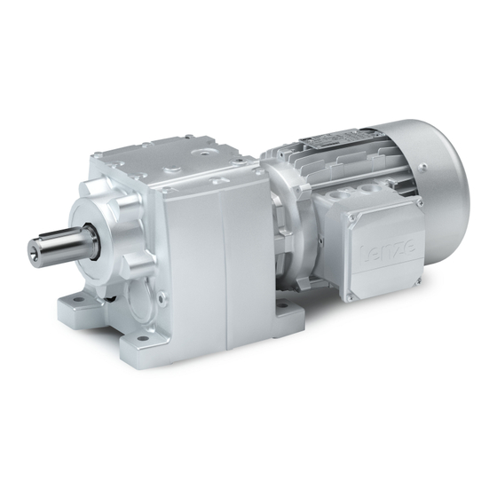
Page 9: Features
Product information Features Features The following figure provides an overview of the elements and connections on the product. Their position, size and appearance may vary. Ventilation (depending on the mounting position) Temperature monitoring Oil filler plug (depending on the mounting position) Oil control plug (depending on the mounting position) Cooling... -
Page 10: The Modular System
Product information The modular system The modular system Values printed in bold are standard designs. Values that are not printed in bold are potential extensions, some of them including a surcharge. Geared motors up to 450 Nm Gearboxes g500-H45 g500-H100 g500-H140 g500-H210 g500-H320... - Page 11 Product information The modular system Geared motors 600 Nm to 3000 Nm Gearboxes g500-H600 g500-H850 g500-H1500 g500-H3000 Min. motor assignment MF□MA□□063 MF□MA□□063 MF□MA□□063 MF□MA□□063 Max. motor assignment MF□MA□□132 MF□MA□□132 MF□MA□□132 MF□MA□□132 Technical data Max. output torque 1500 3000 Min. drive power 0.55 0.55 0.55...
-
Page 12: Designs
Product information The modular system Designs Designs Gearbox designs Observe the available gearbox designs! 4The modular system ^ 10 The VCP design (reinforced flange) is suitable for absorbing high radial and axial forces ^ 50 Solid shaft, with foot Without centring (VBR) With centring (VAR) Flange with through holes (VAK) Solid shaft, without foot... -
Page 13: Mounting Positions
Product information The modular system Mounting positions Mounting positions Details of the mounting position are needed to ensure the corresponding lubricant amount, position of the ventilation, oil checks and oil drain plug on the gearbox. To reduce the number of different versions, the following gearboxes can also be ordered with combined mounting positions: g500-H45 in mounting position M1-M6 (A-F) •... - Page 14 Product information The modular system Mounting positions Positions of the terminal boxes/connectors Power terminal box Blower terminal box HAN connector with/without ICN connector with/without ICN connector Positions of the connections Power terminal box Blower terminal box HAN connector ICN cable glands/connectors ICN cable glands/connectors Positions of the 8400 motec frequency inverters 8400 motec positions...
- Page 15 Product information The modular system Mounting positions Position of the manual release lever...
-
Page 16: Information On Project Planning
Information on project planning Safety instructions Basic safety instructions Information on project planning Safety instructions Basic safety instructions Disregarding the following basic safety instructions and safety information may lead to severe personal injury and damage to property! Only use the product as directed. •... -
Page 17: Residual Hazards
Information on project planning Safety instructions Residual hazards Residual hazards Even if notes given are taken into consideration and protective measures are implemented, the occurrence of residual risks cannot be fully prevented. The user must take the residual hazards mentioned into consideration in the risk assessment for his/her machine/system. - Page 18 Information on project planning Safety instructions Residual hazards Gearbox protection Excessive vibration accelerations and resonances will damage the gearbox. • Do not operate the gearbox at vibration accelerations > 2 g (20 m/s ) of the machine. Do not operate the gearbox in the resonance range of the machine. Excessive torques will damage the gearboxes.
-
Page 19: General Information
Information on project planning General information General information Operation on a frequency inverter Large setting ranges and optimum operation with rated torque. These are the strengths of the MF motor on the frequency inverter. Compared to the 50-Hz operation, the setting range increases by 250 %. - Page 20 Operation with integral fan and "holding current reduction" brake control Operation with blower Operation below 5 Hz is possible depending on the application and the control mode. Verification of the application by Lenze required. Thermal power limit The thermal power limit, defined by the heat balance, limits the permissible continuous gearbox power.
- Page 21 Information on project planning General information Possible ways of extending the application area Shaft sealing ring made of FKM material/Viton (option) • Reducing the lubricant amount (after consultation with Lenze) • Cooling the geared motor by air convection on the machine/system •...
-
Page 22: Drive Dimensioning
With the «Drive Solution Designer«, you can design the drive both quickly and to a high quality. The software contains profound and proven expertise with regard to drive applications and mechatronic drive components. Please get in touch with your Lenze representative. Workflow Inverter operation... - Page 23 Information on project planning Drive dimensioning Define required input variables Required input variables Note Symbol Unit Operating time / day Ambient temperature °C Site altitude amsl Radial force rated Axial force rated Transmission element at the output Gear wheels, sprockets … Effective diameter of the transmission element Load torque For short-term load peaks...
- Page 24 Information on project planning Drive dimensioning Gearbox efficiency Gearboxes Gearbox efficiency η g500-H 2-stage 0.96 3-stage 0.95 4-stage 0.94 Determine product on the basis of the forces Transmission element Gear wheels Sprockets Toothed belt pulleys Narrow V-belt (depending on the (depending on the pretension) pretension)
- Page 25 Information on project planning Drive dimensioning Application factor k 24 h 16 h 8 h 1000 1200 1400 1600 1/h Application factor Switching rate Check and select product Data 4Selection tables ^ 55 Inverter operation Selection table Check Unit Note ≥...
-
Page 26: Final Configuration
Information on project planning Final configuration Final configuration Screening Connection dimensions Output shaft Output flange/foot Mounting position Geared motor Connector/terminal box Driven shaft/output flange Product extensions Torque plate Shaft cover Connector/terminal box Brake Feedback Blower Temperature monitoring Second shaft end Handwheel Protection cover More information about the final configuration:... -
Page 27: Surface And Corrosion Protection
Information on project planning Final configuration Surface and corrosion protection Surface and corrosion protection Depending on the ambient conditions, the surface and corrosion protection system (called OKS) offers tailor-made solutions for optimum protection. Various surface coatings ensure reliable functioning even at high air humidity, in outdoor installations, or in the presence of atmospheric contamination. -
Page 28: Lubricants
Information on project planning Final configuration Lubricants Lubricants The following gearboxes are lubricated for life: g500-H45 • g500-H100 • g500-H140 • Recommended lubricants: Lubricant CLP 220 CLP 460 CLP HC 220 CLP HC 320 Ambient temperature 0 … +40 °C -30 …... -
Page 29: Ventilation
Information on project planning Final configuration Ventilation Ventilation No venting measures are required for the g500-B45 … B240 gearboxes. The g500-B240 gearbox can optionally be equipped with breather elements. From g500-B450 onwards, the gearboxes are supplied with breather elements as standard. To reduce the number of different versions, the following gearboxes can also be ordered with combined mounting positions: g500-H45 in mounting position M1-M6 (A-F) - Page 30 Information on project planning Final configuration Ventilation g500-H210 ... H450 Mounting position M1 (A) Mounting position M2 (D) Mounting position M3 (B) Filling and ventilation Control Drain...
- Page 31 Information on project planning Final configuration Ventilation Mounting position M4 (C) Mounting position M5 (F) Mounting position M6 (E) Filling and ventilation Control ① ② Drain g500-H210 ① g500-H320 ② g500-H450...
- Page 32 Information on project planning Final configuration Ventilation g500-H600 ... H3000 Mounting position M1 (A) Mounting position M2 (D) Mounting position M3 (B) Filling and ventilation Check Drain...
- Page 33 Information on project planning Final configuration Ventilation Mounting position M4 (C) Mounting position M5 (F) Mounting position M6 (E) Filling and ventilation Control Drain Gearbox with oil compensation reservoir for mounting position M4 (C) In order to guarantee a reliable lubrication of the toothed parts in mounting position M4 (C) (motor is on the gearbox vertical from the top), a high filling level is required in the gearbox.
- Page 34 Information on project planning Final configuration Ventilation Dimensions of the oil compensation reservoir For the following gearboxes in mounting position M4 (C), which exceed the specified min. input speed, an oil expansion reservoir is required depending on the specified gear ratio: g500-H1500 g500-H3000 Gearbox ratio...
-
Page 35: Mechanical Installation
• nameplate and in this documentation. Ambient media − especially chemically aggressive ones − may damage shaft sealing rings, • lacquers and plastics. Lenze offers special surface and corrosion protection in this case. • Transport Ensure appropriate handling. • Make sure that all component parts are securely mounted. Secure or remove loose •... -
Page 36: Electrical Installation
Reduction of the DC-bus voltage (threshold for brake chopper voltage) • Use of filters, chokes • Use of special motor cables • Preparation EMC-compliant wiring The EMC-compliant wiring is described in detail in the documentation of the Lenze inverters. -
Page 37: Technical Data
The ratings apply to the operating mode S1 (acc. to EN 60034-1). • NOTICE In case of other operating conditions, the achievable values can differ for those mentioned. ▶ In case of extreme operating conditions, please get in touch with your Lenze representative. -
Page 38: Standards And Operating Conditions
Technical data Standards and operating conditions Conformities and approvals Standards and operating conditions Conformities and approvals More information and certificates of approval can be found under g500 + MF helical geared motors (Lenze.com) Europe Conformity/ Product Country Law/standard Description Special feature... -
Page 39: Environmental Conditions
Technical data Standards and operating conditions Environmental conditions Environmental conditions Climate Storage EN 60721-3-1:1997 1K3 (-25 ... +60 °C) Transport EN 60721-3-2:1997 2K3 (-25 ... +70 °C) 3K3 (-20 ...+40 °C) EN 60721-3-3:1995 + Operation A2:1997 3K3 (-20 ...+60 °C) Operation without brake, self-ventilated Site altitude 0 …... -
Page 40: Data Overview
Technical data Data overview Data overview The following tables contain the most important data of the gearbox with the attachable motors of a geared motor. In order to calculate the exact ratio, the number of teeth z (driven) can be divided by the number of teeth z (driving). - Page 41 Technical data Data overview g500-H100, 3-stage gearboxes Max. output torque Ratio Number of teeth Max. backlash Standard 2, max 59.505 6248 83.307 6248 106.259 15620 130.167 163.638 17182 198.597 69509 255.769 107423 324.156 499201 1540 406.221 56871 519.188 8307 g500-H140, 2-stage gearboxes Max.
- Page 42 Technical data Data overview g500-H140, 3-stage gearboxes Max. output torque Ratio Number of teeth Max. backlash Standard 2, max 57.582 12956 73.447 32390 84.732 37367 92.693 6952 118.231 17380 144.833 182.076 19118 220.974 77341 284.588 119527 360.681 555449 1540 451.993 63279 577.688 9243...
- Page 43 Technical data Data overview g500-H210, 4-stage gearboxes Max. output torque Ratio Number of teeth Max. backlash Standard 2, max 318.197 100232 407.216 538747 1323 494.212 4358953 8820 632.132 1115081 1764 820.622 1723307 2100 969.983 285175 1254.762 26350 1522.825 234515 1946.307 171275 2532.292 60775...
- Page 44 Technical data Data overview g500-H320, 4-stage gearboxes Max. output torque Ratio Number of teeth Max. backlash Standard 2, max 346.692 109208 443.683 586993 1323 567.502 750805 1323 736.721 232067 894.111 1877633 2100 1221.302 76942 1589.005 300322 1928.475 1214939 2464.764 177463 g500-H450, 2-stage gearboxes Max.
- Page 45 Technical data Data overview g500-H450, 4-stage gearboxes Max. output torque Ratio Number of teeth Max. backlash Standard 2, max 365.689 16456 511.964 115192 653.016 41140 799.944 14399 1005.644 45254 1295.148 34969 1641.444 14773 1992.117 119527 2496.450 49929 3190.688 51051 g500-H600, 2-stage gearboxes Max.
- Page 46 Technical data Data overview g500-H600, 4-stage gearboxes Max. output torque Ratio Number of teeth Max. backlash Standard 2, max 198.970 2014576 10125 253.789 1007288 3969 320.294 1080992 3375 408.538 540496 1323 500.459 67562 651.391 5540084 8505 810.267 2297108 2835 1048.581 2972728 2835 1272.596...
- Page 47 Technical data Data overview g500-H850, 4-stage gearboxes Max. output torque Ratio Number of teeth Max. backlash Standard 2, max 234.319 439348 1875 294.334 264901 368.019 1150058 3125 473.807 71071 575.029 575029 1000 616.701 416273 767.116 172601 992.738 223366 1204.823 903617 1462.217 7311083 5000...
- Page 48 Technical data Data overview g500-H1500, 4-stage gearboxes Max. output torque Ratio Number of teeth Max. backlash Standard 2, max 1500 225.125 99280 1500 281.416 2849336 10125 1500 350.054 1181432 3375 1500 446.497 84388 1500 572.324 2086121 3645 1500 701.446 3409027 4860 1500 872.530...
- Page 49 Technical data Data overview g500-H3000, 4-stage gearboxes Max. output torque Ratio Number of teeth Max. backlash Standard 2, max 2650 226.604 61183 3000 292.511 987224 3375 3000 376.393 50813 3000 457.048 123403 3000 489.908 595238 1215 3000 594.888 722789 1215 3000 739.983 299693...
-
Page 50: Radial Forces And Axial Forces
Technical data Radial forces and axial forces Radial forces and axial forces Permissible radial force The calculation of the permissible radial force must take account of the additional load factor rad, perm rad,max Permissible axial force If there is no radial force, the maximum axial force is 50% of the value in the table F rad,max = 0.5 x F ax, zul... - Page 51 1.3 and an input speed of 1400 rpm. In case of different operating conditions, considerably higher forces can be transmitted. Please get in touch with your Lenze representative A hollow shaft with shrink disc (SAR/SBR/SCR/SDR/SAK/SCK) requires a check by Lenze.
- Page 52 Technical data Radial forces and axial forces Max. radial force, gearbox with/without foot with threaded pitch circle (V□R/V□K) Output speed n [rpm] Getriebe 1000 Max. radial force F [rated] rad,max g500-H45 1100 1400 1500 1500 g500-H100 1000 1200 1500 1700 1700 1700 1700...
- Page 53 Technical data Radial forces and axial forces Effective direction factor f on the output shaft α g500-H45 1.45 1.40 1.35 1.30 1.25 1.20 1.15 1.10 1.05 1.00 30 60 90 120 150 180 210 240 270 300 330 360 α 2-stage: Direction of rotation R 2-stage: Direction of rotation L g500-H100...
- Page 54 Technical data Radial forces and axial forces g500-H850 g500-H1500 1.25 1.35 1.30 1.20 1.25 1.15 1.20 1.15 1.10 1.10 1.05 1.05 1.00 1.00 30 60 90 120 150 180 210 240 270 300 330 360 30 60 90 120 150 180 210 240 270 300 330 360 α...
-
Page 55: Selection Tables
5 Hz to 120 Hz: Operation at constant torque. Below 20 Hz (n ): Derating without blower. Below 5 Hz (n ): Verification of the application by Lenze required. Below 5 Hz (n ): Verification of the application by Lenze required. Notes on the selection tables The selection tables represent the available combinations of gearbox, number of stages, ratio and motor for the mounting position M1. - Page 56 Technical data Selection tables 120 Hz: 0.55 kW Inverter operation Geared motor 5 Hz - - 20 Hz - 120 Hz (1:24) kgcm² 55.8 1325 3.960 2.597 g500-H45 MFXMA 063-32 44.4 1053 4.602 3.267 g500-H140 MFXMA 063-32 43.2 1026 4.225 3.354 g500-H100 MFXMA 063-32...
- Page 57 Technical data Selection tables Inverter operation Geared motor 5 Hz - - 20 Hz - 120 Hz (1:24) kgcm² 52.4 12.7 69.0 72.8 69.0 3.834 47.276 g500-H320 MFXMA 063-32 53.7 12.6 71.0 72.1 71.0 3.761 47.679 g500-H210 MFXMA 063-32 53.8 12.4 71.0 70.8...
- Page 58 Technical data Selection tables Inverter operation Geared motor 5 Hz - - 20 Hz - 120 Hz (1:24) kgcm² 3.922 446.497 g500-H1500 MFXMA 063-32 3.804 473.807 g500-H850 MFXMA 063-32 4.106 489.908 g500-H3000 MFXMA 063-32 3.795 500.459 g500-H600 MFXMA 063-32 3.958 572.324 g500-H1500 MFXMA 063-32...
- Page 59 Technical data Selection tables 120 Hz: 0.75 kW Inverter operation Geared motor 5 Hz - - 20 Hz - 120 Hz (1:24) kgcm² 55.8 1309 3.960 2.597 g500-H45 MFXMA 063-42 44.4 1041 4.602 3.267 g500-H140 MFXMA 063-42 43.2 1014 4.225 3.354 g500-H100 MFXMA 063-42...
- Page 60 Technical data Selection tables Inverter operation Geared motor 5 Hz - - 20 Hz - 120 Hz (1:24) kgcm² 73.1 12.6 98.0 71.3 98.0 3.761 47.679 g500-H210 MFXMA 063-42 73.3 12.4 98.0 70.0 98.0 3.826 48.571 g500-H210 MFXMA 063-42 75.0 12.3 69.5 3.875...
- Page 61 Technical data Selection tables Inverter operation Geared motor 5 Hz - - 20 Hz - 120 Hz (1:24) kgcm² 1173 1566 1566 3.871 788.632 g500-H3000 MFXMA 063-42 1298 1733 1733 3.872 872.530 g500-H1500 MFXMA 063-42 1424 1902 1902 3.851 957.625 g500-H3000 MFXMA 063-42 1843...
- Page 62 Technical data Selection tables 120 Hz: 1.1 kW Inverter operation Geared motor 5 Hz - - 20 Hz - 120 Hz (1:24) kgcm² 44.4 1068 13.702 3.267 g500-H140 MFXMA 071-32 43.2 1041 13.325 3.354 g500-H100 MFXMA 071-32 42.8 1030 14.330 3.389 g500-H210 MFXMA 071-32...
- Page 63 Technical data Selection tables Inverter operation Geared motor 5 Hz - - 20 Hz - 120 Hz (1:24) kgcm² 96.4 13.7 79.9 13.458 43.676 g500-H600 MFXMA 071-32 13.3 77.3 13.331 45.136 g500-H850 MFXMA 071-32 12.9 75.2 12.870 46.407 g500-H320 MFXMA 071-32 12.7 73.8 12.934...
- Page 64 Technical data Selection tables Inverter operation Geared motor 5 Hz - - 20 Hz - 120 Hz (1:24) kgcm² 2082 2713 2713 12.951 957.625 g500-H3000 MFXMA 071-32 2695 3511 3511 12.930 1239.279 g500-H3000 MFXMA 071-32...
- Page 65 Technical data Selection tables 120 Hz: 1.5 kW Inverter operation Geared motor 5 Hz - - 20 Hz - 120 Hz (1:24) kgcm² 44.4 10.0 13.0 1056 13.0 13.702 3.267 g500-H140 MFXMA 071-42 43.2 10.3 14.0 1029 14.0 13.325 3.354 g500-H100 MFXMA 071-42 42.8...
- Page 66 Technical data Selection tables Inverter operation Geared motor 5 Hz - - 20 Hz - 120 Hz (1:24) kgcm² 13.3 76.4 13.331 45.136 g500-H850 MFXMA 071-42 12.9 74.3 12.870 46.407 g500-H320 MFXMA 071-42 12.7 73.0 12.934 47.276 g500-H320 MFXMA 071-42 12.6 72.4 12.861...
- Page 67 Technical data Selection tables 120 Hz: 2.2 kW Inverter operation Geared motor 5 Hz - - 20 Hz - 120 Hz (1:24) kgcm² 44.4 14.3 19.0 1071 19.0 28.902 3.267 g500-H140 MFXMA 080-32 43.2 14.6 20.0 1044 20.0 28.525 3.354 g500-H100 MFXMA 080-32 42.8...
- Page 68 Technical data Selection tables Inverter operation Geared motor 5 Hz - - 20 Hz - 120 Hz (1:24) kgcm² 21.2 29.141 28.315 g500-H850 MFXMA 080-32 20.3 28.152 29.548 g500-H320 MFXMA 080-32 19.8 28.132 30.357 g500-H210 MFXMA 080-32 19.2 29.108 31.197 g500-H600 MFXMA 080-32 19.3...
- Page 69 Technical data Selection tables 120 Hz: 3 kW Inverter operation Geared motor 5 Hz - - 20 Hz - 120 Hz (1:24) kgcm² 44.4 19.7 26.0 1065 26.0 28.902 3.267 g500-H140 MFXMA 080-42 43.2 20.2 27.0 1038 27.0 28.525 3.354 g500-H100 MFXMA 080-42 42.8...
- Page 70 Technical data Selection tables Inverter operation Geared motor 5 Hz - - 20 Hz - 120 Hz (1:24) kgcm² 19.2 29.108 31.197 g500-H600 MFXMA 080-42 19.3 28.379 31.167 g500-H450 MFXMA 080-42 19.1 28.423 31.356 g500-H600 MFXMA 080-42 16.8 97.5 30.325 35.689 g500-H1500 MFXMA 080-42...
- Page 71 Technical data Selection tables 120 Hz: 4 kW Inverter operation Geared motor 5 Hz - - 20 Hz - 120 Hz (1:24) kgcm² 44.4 24.4 35.0 1065 35.0 32.902 3.267 g500-H140 MFXMA 090-32 43.2 25.1 35.0 1038 35.0 32.525 3.354 g500-H100 MFXMA 090-32 42.8...
- Page 72 Technical data Selection tables Inverter operation Geared motor 5 Hz - - 20 Hz - 120 Hz (1:24) kgcm² 15.0 87.2 32.762 39.925 g500-H600 MFXMA 090-32 14.9 86.3 32.238 40.333 g500-H450 MFXMA 090-32 14.8 85.8 32.264 40.578 g500-H600 MFXMA 090-32 14.5 84.2 33.726...
- Page 73 Technical data Selection tables 120 Hz: 5.5 kW Inverter operation Geared motor 5 Hz - - 20 Hz - 120 Hz (1:24) kgcm² 44.4 33.0 47.0 1079 47.0 67.900 3.267 g500-H600 MFXMA 100-12 42.8 34.2 49.0 1040 49.0 62.530 3.389 g500-H210 MFXMA 100-12 42.8...
- Page 74 Technical data Selection tables Inverter operation Geared motor 5 Hz - - 20 Hz - 120 Hz (1:24) kgcm² 15.9 93.3 62.932 37.799 g500-H850 MFXMA 100-12 14.5 85.2 62.726 41.350 g500-H850 MFXMA 100-12 13.9 81.4 62.711 43.313 g500-H1500 MFXMA 100-12 13.3 78.1 61.531...
- Page 75 Technical data Selection tables 120 Hz: 7.5 kW Inverter operation Geared motor 5 Hz - - 20 Hz - 120 Hz (1:24) kgcm² 44.4 45.3 64.0 1076 64.0 67.900 3.267 g500-H600 MFXMA 100-32 42.8 47.0 67.0 1037 67.0 62.530 3.389 g500-H210 MFXMA 100-32 42.8...
- Page 76 Technical data Selection tables Inverter operation Geared motor 5 Hz - - 20 Hz - 120 Hz (1:24) kgcm² 1256 54.3 1256 70.627 64.744 g500-H3000 MFXMA 100-32 1077 1529 44.6 1529 63.783 78.794 g500-H1500 MFXMA 100-32 1470 2086 32.7 2086 65.608 107.541 g500-H3000...
- Page 77 Technical data Selection tables 120 Hz: 11 kW Inverter operation Geared motor 5 Hz - - 20 Hz - 120 Hz (1:24) kgcm² 46.1 58.0 91.0 1122 91.0 121.097 3.147 g500-H850 MFXMA 112-22 44.4 60.2 94.0 1081 94.0 113.900 3.267 g500-H600 MFXMA 112-22 42.8...
- Page 78 Technical data Selection tables 120 Hz: 15 kW Inverter operation Geared motor 5 Hz - - 20 Hz - 120 Hz (1:24) kgcm² 46.1 78.8 1131 350.097 3.147 g500-H850 MFXMA 132-12 44.4 81.8 1090 342.900 3.267 g500-H600 MFXMA 132-12 42.1 86.2 1034 340.943...
- Page 79 Technical data Selection tables 120 Hz: 18.5 kW Inverter operation Geared motor 5 Hz - - 20 Hz - 120 Hz (1:24) kgcm² 46.1 97.1 1131 350.097 3.147 g500-H850 MFXMA 132-22 44.4 1090 342.900 3.267 g500-H600 MFXMA 132-22 42.1 1034 340.943 3.444 g500-H450...
-
Page 80: Motor - Inverter Assignment
Technical data Motor – inverter assignment 120 Hz: 22 kW Inverter operation Geared motor 5 Hz - - 20 Hz - 120 Hz (1:24) kgcm² 46.1 1128 350.097 3.147 g500-H850 MFXMA 132-32 44.4 1087 342.900 3.267 g500-H600 MFXMA 132-32 42.1 1031 340.943 3.444... -
Page 81: Dimensions
If the mounting area (foot support) towards the motor is longer than the gearbox foot, some motors collide with the mounting area! For an accurate check of the geometrical data, Lenze recommends the use of the »Product Finder« at www.Lenze.com. -
Page 82: Basic Dimensions
Technical data Dimensions Basic dimensions Basic dimensions g500-H45, 2-stage Gearbox design: Solid shaft with foot (VBR) The dimensions are also valid for solid shaft without keyway Ø20 x 40 (G□□)! Motor series MFXMA Motor 063-32 063-42 Total length Motor length Motor diameter Motor/connection distance Δ... - Page 83 Technical data Dimensions Basic dimensions g500-H45, 2-stage Gearbox design: Solid shaft with centering (VCR) The dimensions are also valid for solid shaft without keyway Ø20 x 40 (G□□)! Motor series MFXMA Motor 063-32 063-42 Total length Motor length Motor diameter Motor/connection distance Δ...
- Page 84 Technical data Dimensions Basic dimensions g500-H45, 2-stage Gearbox design: Solid shaft with flange (VCK) The dimensions are also valid for solid shaft without keyway Ø20 x 40 (G□□)! Motor series MFXMA Motor 063-32 063-42 Total length Motor length Motor diameter Motor/connection distance Δ...
- Page 85 Technical data Dimensions Basic dimensions g500-H100, 2-stage Gearbox design: Solid shaft with foot (VBR) The dimensions are also valid for solid shaft without keyway (G□□)! Motor series MFXMA Motor 063-32 071-32 080-32 090-32 063-42 071-42 080-42 Total length Motor length Motor diameter Motor/connection distance Δ...
- Page 86 Technical data Dimensions Basic dimensions g500-H100, 2-stage Gearbox design: Solid shaft with centering (VAR/VCR) The dimensions are also valid for solid shaft without keyway (G□□)! Motor series MFXMA Motor 063-32 071-32 080-32 090-32 063-42 071-42 080-42 Total length Motor length Motor diameter Motor/connection distance Δ...
- Page 87 Technical data Dimensions Basic dimensions g500-H100, 2-stage Gearbox design: Solid shaft with flange (VAK/VCK) The dimensions are also valid for solid shaft without keyway (G□□)! Motor series MFXMA Motor 063-32 071-32 080-32 090-32 063-42 071-42 080-42 Total length Motor length Motor diameter Motor/connection distance Δ...
- Page 88 Technical data Dimensions Basic dimensions g500-H100, 2-stage Gearbox design: Solid shaft with flange in reinforced design (VCP) The dimensions are also valid for solid shaft without keyway (G□□)! Motor series MFXMA Motor 063-32 071-32 080-32 090-32 063-42 071-42 080-42 Total length Motor length Motor diameter Motor/connection distance...
- Page 89 Technical data Dimensions Basic dimensions g500-H140, 2-stage Gearbox design: Solid shaft with foot (VBR) The dimensions are also valid for solid shaft without keyway (G□□)! Motor series MFXMA Motor 063-32 071-32 080-32 090-32 063-42 071-42 080-42 Total length Motor length Motor diameter Motor/connection distance Δ...
- Page 90 Technical data Dimensions Basic dimensions g500-H140, 2-stage Gearbox design: Solid shaft with centering (VAR/VCR) The dimensions are also valid for solid shaft without keyway (G□□)! Motor series MFXMA Motor 063-32 071-32 080-32 090-32 063-42 071-42 080-42 Total length Motor length Motor diameter Motor/connection distance Δ...
- Page 91 Technical data Dimensions Basic dimensions g500-H140, 2-stage Gearbox design: Solid shaft with flange (VAK/VCK) The dimensions are also valid for solid shaft without keyway (G□□)! Motor series MFXMA Motor 063-32 071-32 080-32 090-32 063-42 071-42 080-42 Total length Motor length Motor diameter Motor/connection distance Δ...
- Page 92 Technical data Dimensions Basic dimensions g500-H140, 2-stage Gearbox design: Solid shaft with flange in reinforced design (VCP) The dimensions are also valid for solid shaft without keyway (G□□)! Motor series MFXMA Motor 063-32 071-32 080-32 090-32 063-42 071-42 080-42 Total length Motor length Motor diameter Motor/connection distance...
- Page 93 Technical data Dimensions Basic dimensions g500-H210, 2-/3-stage Gearbox design: Solid shaft with foot (VBR) The dimensions are also valid for solid shaft without keyway (G□□)! Motor series MFXMA Motor 063-32 071-32 080-32 090-32 100-12 063-42 071-42 080-42 100-32 Total length Motor length Motor diameter Motor/connection distance...
- Page 94 Technical data Dimensions Basic dimensions g500-H210, 2-/3-stage Gearbox design: Solid shaft with centering (VAR/VCR) The dimensions are also valid for solid shaft without keyway (G□□)! Motor series MFXMA Motor 063-32 071-32 080-32 090-32 100-12 063-42 071-42 080-42 100-32 Total length Motor length Motor diameter Motor/connection distance...
- Page 95 Technical data Dimensions Basic dimensions g500-H210, 2-/3-stage Gearbox design: Solid shaft with flange (VAK/VCK) The dimensions are also valid for solid shaft without keyway (G□□)! Motor series MFXMA Motor 063-32 071-32 080-32 090-32 100-12 063-42 071-42 080-42 100-32 Total length Motor length Motor diameter Motor/connection distance...
- Page 96 Technical data Dimensions Basic dimensions g500-H210, 2-/3-stage Gearbox design: Solid shaft with flange in reinforced design (VCP) The dimensions are also valid for solid shaft without keyway (G□□)! Motor series MFXMA Motor 063-32 071-32 080-32 090-32 100-12 063-42 071-42 080-42 100-32 Total length Motor length...
- Page 97 Technical data Dimensions Basic dimensions g500-H320, 2-/3-stage Gearbox design: Solid shaft with foot (VBR) The dimensions are also valid for solid shaft without keyway (G□□)! Motor series MFXMA Motor 063-32 071-32 080-32 090-32 100-12 112-22 063-42 071-42 080-42 100-32 Total length Motor length Motor diameter Motor/connection distance...
- Page 98 Technical data Dimensions Basic dimensions g500-H320, 2-/3-stage Gearbox design: Solid shaft with centering (VAR/VCR) The dimensions are also valid for solid shaft without keyway (G□□)! Motor series MFXMA Motor 063-32 071-32 080-32 090-32 100-12 112-22 063-42 071-42 080-42 100-32 Total length Motor length Motor diameter Motor/connection distance...
- Page 99 Technical data Dimensions Basic dimensions g500-H320, 2-/3-stage Gearbox design: Solid shaft with flange (VAK/VCK) The dimensions are also valid for solid shaft without keyway (G□□)! Motor series MFXMA Motor 063-32 071-32 080-32 090-32 100-12 112-22 063-42 071-42 080-42 100-32 Total length Motor length Motor diameter Motor/connection distance...
- Page 100 Technical data Dimensions Basic dimensions g500-H320, 2-/3-stage Gearbox design: Solid shaft with flange in reinforced design (VCP) The dimensions are also valid for solid shaft without keyway (G□□)! Motor series MFXMA Motor 063-32 071-32 080-32 090-32 100-12 112-22 063-42 071-42 080-42 100-32 Total length...
- Page 101 Technical data Dimensions Basic dimensions g500-H450, 2-/3-stage Gearbox design: Solid shaft with foot (VBR) The dimensions are also valid for solid shaft without keyway Ø35 x 70 (G□□)! Motor series MFXMA Motor 063-32 071-32 080-32 090-32 100-12 112-22 132-12 063-42 071-42 080-42 100-32...
- Page 102 Technical data Dimensions Basic dimensions g500-H450, 2-/3-stage Gearbox design: Solid shaft with centering (VAR/VCR) The dimensions are also valid for solid shaft without keyway Ø35 x 70 (G□□)! Motor series MFXMA Motor 063-32 071-32 080-32 090-32 100-12 112-22 132-12 063-42 071-42 080-42 100-32...
- Page 103 Technical data Dimensions Basic dimensions g500-H450, 2-/3-stage Gearbox design: Solid shaft with flange (VAK/VCK) The dimensions are also valid for solid shaft without keyway Ø35 x 70 (G□□)! Motor series MFXMA Motor 063-32 071-32 080-32 090-32 100-12 112-22 132-12 063-42 071-42 080-42 100-32...
- Page 104 Technical data Dimensions Basic dimensions g500-H450, 2-/3-stage Gearbox design: Solid shaft with flange in reinforced design (VCP) The dimensions are also valid for solid shaft without keyway Ø35 x 70 (G□□)! Motor series MFXMA Motor 063-32 071-32 080-32 090-32 100-12 112-22 132-12 063-42...
- Page 105 Technical data Dimensions Basic dimensions g500-H600, 2-/3-stage Gearbox design: Solid shaft with foot (VBR) The dimensions are also valid for solid shaft without keyway Ø35 x 70 (G□□)! Motor series MFXMA Motor 063-32 071-32 080-32 090-32 100-12 112-22 132-12 063-42 071-42 080-42 100-32...
- Page 106 Technical data Dimensions Basic dimensions g500-H600, 2-/3-stage Gearbox design: Solid shaft with centering (VAR/VCR) The dimensions are also valid for solid shaft without keyway Ø35 x 70 (G□□)! Motor series MFXMA Motor 063-32 071-32 080-32 090-32 100-12 112-22 132-12 063-42 071-42 080-42 100-32...
- Page 107 Technical data Dimensions Basic dimensions g500-H600, 2-/3-stage Gearbox design: Solid shaft with flange (VAK/VCK) The dimensions are also valid for solid shaft without keyway Ø35 x 70 (G□□)! Motor series MFXMA Motor 063-32 071-32 080-32 090-32 100-12 112-22 132-12 063-42 071-42 080-42 100-32...
- Page 108 Technical data Dimensions Basic dimensions g500-H850, 2-/3-stage Gearbox design: Solid shaft with foot (VBR) The dimensions are also valid for solid shaft without keyway (G□□)! Motor series MFXMA Motor 063-32 071-32 080-32 090-32 100-12 112-22 132-12 063-42 071-42 080-42 100-32 132-22 132-32 Total length...
- Page 109 Technical data Dimensions Basic dimensions g500-H850, 2-/3-stage Gearbox design: Solid shaft with centering (VAR/VCR) The dimensions are also valid for solid shaft without keyway (G□□)! Motor series MFXMA Motor 063-32 071-32 080-32 090-32 100-12 112-22 132-12 063-42 071-42 080-42 100-32 132-22 132-32 Total length...
- Page 110 Technical data Dimensions Basic dimensions g500-H850, 2-/3-stage Gearbox design: Solid shaft with flange (VAK/VCK) The dimensions are also valid for solid shaft without keyway (G□□)! Motor series MFXMA Motor 063-32 071-32 080-32 090-32 100-12 112-22 132-12 063-42 071-42 080-42 100-32 132-22 132-32 Total length...
- Page 111 Technical data Dimensions Basic dimensions g500-H1500, 2-/3-stage Gearbox design: Solid shaft with foot (VBR) The dimensions are also valid for solid shaft without keyway (G□□)! Motor series MFXMA Motor 071-32 063-32 080-32 090-32 100-12 112-22 132-12 071-42 063-42 080-42 100-32 132-22 132-32 Total length...
- Page 112 Technical data Dimensions Basic dimensions g500-H1500, 2-/3-stage Gearbox design: Solid shaft with centering (VAR/VCR) The dimensions are also valid for solid shaft without keyway (G□□)! Motor series MFXMA Motor 071-32 063-32 080-32 090-32 100-12 112-22 132-12 071-42 063-42 080-42 100-32 132-22 132-32 Total length...
- Page 113 Technical data Dimensions Basic dimensions g500-H1500, 2-/3-stage Gearbox design: Solid shaft with flange (VAK/VCK) The dimensions are also valid for solid shaft without keyway (G□□)! Motor series MFXMA Motor 071-32 063-32 080-32 090-32 100-12 112-22 132-12 071-42 063-42 080-42 100-32 132-22 132-32 Total length...
- Page 114 Technical data Dimensions Basic dimensions g500-H3000, 2-/3-stage Gearbox design: Solid shaft with foot (VBR) The dimensions are also valid for solid shaft without keyway (G□□)! Motor series MFXMA Motor 063-32 071-32 080-32 090-32 100-12 112-22 132-12 063-42 071-42 080-42 100-32 132-22 132-32 Total length...
- Page 115 Technical data Dimensions Basic dimensions g500-H3000, 2-/3-stage Gearbox design: Solid shaft with centering (VAR/VCR) The dimensions are also valid for solid shaft without keyway (G□□)! Motor series MFXMA Motor 063-32 071-32 080-32 090-32 100-12 112-22 132-12 063-42 071-42 080-42 100-32 132-22 132-32 Total length...
- Page 116 Technical data Dimensions Basic dimensions g500-H3000, 2-/3-stage Gearbox design: Solid shaft with flange (VAK/VCK) The dimensions are also valid for solid shaft without keyway (G□□)! NOTICE ▶ Additionally secure the Ø300 output flange with two spiral pins. Motor series MFXMA Motor 063-32 071-32...
-
Page 117: Gearbox With Pre-Stage
Technical data Dimensions Gearbox with pre-stage Gearbox with pre-stage g500-H100 ... H140, 3-stage g500-H210 ... H3000, 4-stage The geared motor dimensions are taken from the basic dimensions except for the overall length "L" and the center distance "a". 4Basic dimensions ^ 82 The total length "L"... -
Page 118: Integrated Inverters
Technical data Dimensions Integrated inverters Integrated inverters 8400 motec Supply voltage 3x 400/480 V 8801071_00 Rated frequency 120 Hz Motor 8400 motec MF☐MA☐☐063-32 E84DVB☐5514S☐☐☐2☐ MF☐MA☐☐063-42 E84DVB☐7514S☐☐☐2☐ MF☐MA☐☐071-32 E84DVB☐1124S☐☐☐2☐ MF☐MA☐☐071-42 E84DVB☐1524S☐☐☐2☐ MF☐MA☐☐080-32 E84DVB☐2224S☐☐☐2☐ MF☐MA☐☐080-42 E84DVB☐3024S☐☐☐2☐ MF☐MA☐☐090-32 E84DVB☐4024S☐☐☐2☐ MF☐MA☐☐100-12 E84DVB☐5524S☐☐☐2☐ MF☐MA☐☐100-32 E84DVB☐7524S☐☐☐2☐ Maße LB und Δ... -
Page 119: Additional Lengths
Technical data Dimensions Additional lengths Additional lengths Self-ventilated motors Motor MF☐MA☐☐ 063-32 071-32 080-32 090-32 100-12 112-22 132-12 063-42 071-42 080-42 100-32 132-22 132-32 Without feedback/brake Δ L mm Brake Δ L [mm] Feedback Δ L [mm] Brake + feedback Δ... -
Page 120: Weights
Technical data Weights Basic weights Weights Basic weights The basic weights are listed in the selection tables. Weights with lubricant for mounting position M1, all data approximate values. The exact values can be found in the delivery documents tables 4Selection ^ 55 Observe weights ... -
Page 121: Product Extensions
Product extensions Motor connection Connection options Product extensions Motor connection Connection options The motor are equipped with a terminal box by default. Alternatively, different connectors can be selected for fast commissioning or maintenance. Terminal box with cable gland Terminal box with ICN connector HAN connector Frequency inverter operation For frequency inverter operation, the base frequencies were set to the following rated... -
Page 122: Assignment Of The Terminal Boxes
Product extensions Motor connection Assignment of the terminal boxes Assignment of the terminal boxes Assignment of the terminal boxes with one temperature monitor Motor MF☐MA☐☐ 063-32 071-32 080-32 090-32 100-12 112-22 132-12 063-42 071-42 080-42 100-32 132-22 132-32 Without product extensions Terminal box ICN connector Power... - Page 123 Product extensions Motor connection Assignment of the terminal boxes Positions of the connectors Positions on the motor terminal box Positions on the blower terminal box Terminal box Positions Note Motor terminal box KK1 Cable glands L, E or R ICN connector: Power L, E or R Motor terminal box KK2 Cable glands...
- Page 124 Product extensions Motor connection Assignment of the terminal boxes Dimensions of KK1 power terminal box P1 P2 Motor MF☐MA☐☐ 063-32 071-32 080-32 090-32 100-12 112-22 132-12 063-42 071-42 080-42 100-32 132-22 132-32 Motor terminal box M16x1.5 M16x1.5 M20x1.5 M20x1.5 M20x1.5 M20x1.5 M32x1.5 M20x1.5...
- Page 125 Product extensions Motor connection Assignment of the terminal boxes Dimensions of KK1 power terminal box with ICN connector Motor MF☐MA☐☐ 063-32 071-32 080-32 090-32 100-12 063-42 071-42 080-42 100-32 Motor terminal box Blower terminal box...
- Page 126 Product extensions Motor connection Assignment of the terminal boxes Dimensions of KK2 power terminal box P1 P2 P1 P2 Motor MF☐MA☐☐ 063-32 071-32 080-32 090-32 100-12 112-22 063-42 071-42 080-42 100-32 Motor terminal box M16x1.5 M16x1.5 M20x1.5 M20x1.5 M20x1.5 M20x1.5 M20x1.5 M20x1.5 M25x1.5...
- Page 127 Product extensions Motor connection Assignment of the terminal boxes Dimensions of KK2/KK3 power terminal box with ICN connector Power/brake connection: Position A. Feedback connection: Position B. For the motors MF☐MA☐☐112-22 ... 132-32 only the connector for the feedback connection is available! The connection for power/brake is made via cable glands.
- Page 128 Product extensions Motor connection Assignment of the terminal boxes Dimensions of KK3 power terminal box P3 P4 P1 P2 Motor MF☐MA☐☐ 063-32 071-32 080-32 090-32 100-12 112-22 132-12 063-42 071-42 080-42 100-32 132-22 132-32 Motor terminal box M25x1.5 M25x1.5 M25x1.5 M25x1.5 M25x1.5 M25x1.5...
-
Page 129: Assignment Of The Connectors Han
Product extensions Motor connection Assignment of the connectors HAN Assignment of the connectors HAN The power, brake and temperature monitoring can be connected in the HAN connector. The designs HAN 10E or HAN modular with two power modules (16 A or 40 A) are available. The HAN 10E connector is only available for motors with the connection method Y/Δ. - Page 130 Product extensions Motor connection Assignment of the connectors HAN Dimensions of HAN connector Motor MF☐MA☐☐ 063-32 071-32 080-32 090-32 100-12 112-22 132-12 063-42 071-42 080-42 100-32 132-22 HAN connector Power/brake Blower terminal box...
-
Page 131: Connection Via Terminal Box
Product extensions Motor connection Connection via terminal box Connection via terminal box Position of the connections Position Meaning Note Power connection For the terminal box "KK1", the position of the cable connections Brake connection "L", "R" or "E" must be specified. PE connection Feedback connection Connection of temperature monitoring... - Page 132 Product extensions Motor connection Connection via terminal box AC brake connection Switching contact - DC switching Terminal box, AC brake via rectifier Contact Name Meaning Mains L1 Tilde Mains N Holding brake (factory-wired) Schalter Switching contact - DC switching Feedback connection Terminal box, resolver Contact Name...
- Page 133 Product extensions Motor connection Connection via terminal box Connection of temperature monitoring Terminal box, temperature monitoring Contact Name Meaning Temperature monitoring: TCO 1TP1 PTC150 thermistor 2TP1 PTC130 thermistor Temperature sensor PT1000 + Temperature sensor PT1000 - 1TP2 PTC150 thermistor 2TP2 PTC130 thermistor Connection of temperature monitoring Blower connection...
-
Page 134: Connection Via Icn Connector
Product extensions Motor connection Connection via ICN connector Connection via ICN connector In order to provide for a quick and error-free connection of Lenze motors to Lenze inverters, we recommend using prefabricated Lenze system cables. Position of the connections Position... - Page 135 Product extensions Motor connection Connection via ICN connector ICN-M23 connector assignment 8-pole ICN M23 8-pole Contact Name Meaning Power phase U PE conductor Power phase W Power phase V Temperature monitoring: TCO Temperature monitoring: TCO BD1 / BA1 Brake DC +/AC ≤ 230 V BD2 / BA2 Brake DC-/AC ≤...
- Page 136 Product extensions Motor connection Connection via ICN connector ICN-M23 connector assignment Incremental and SinCos absolute value encoder Hiperface© Code 20° ICN M23 for incremental and SinCos absolute value encoder Hiperface Contact Name Meaning Track B / +SIN A¯ Track A inverse /-COS Track A / + COS Supply + Mass...
-
Page 137: Connection Via M12 Connector
Product extensions Motor connection Connection via M12 connector Connection via M12 connector M12 pin assignment Incr. encoder IG128-24V-H ICN M12 Contact Name Meaning Supply + Track B Mass Track A... -
Page 138: Connection Via Han Connector
Product extensions Motor connection Connection via HAN connector Connection via HAN connector Position of the connections Note Meaning Power connection Brake connection PE connection Connection of temperature monitoring Additionally for HAN-Modular: • Rectifier connection HAN 10E connector The motor connection is specified in the counter plug. The connector is only suitable for motors with the connection method Y/Δ. - Page 139 Product extensions Motor connection Connection via HAN connector HAN modular connector The motor connection is specified in the terminal box. HAN modular 16 A pin assignment HAN modular 16 A Module Contact Name Meaning Motor winding phase Blank module TKO+PT1000 Temperature monitoring +/AC Brake...
-
Page 140: Brakes
If long motor supply cables are used, pay attention to the ohmic voltage drop along the cable and compensate for it with a higher voltage at the input end of the cable. The following applies to Lenze system cables: Resulting supply voltage U[V] U [V] 0.08... - Page 141 Product extensions Brakes Manual release lever To make positioning and maintenance work easier, the holding and application brake can be ordered with a manual release lever. By using the manual release lever, the brake can be released manually in deenergized operating state. A lockable manual release lever can be ordered as an option.
-
Page 142: Spring-Applied Brakes
Product extensions Brakes Spring-applied brakes Spring-applied brakes NOTICE If used as a service brake, the braking torques are dependent on the motor speed to be braked. ▶ During braking from a high speed and in the event of emergency stops, the braking torque is significantly reduced. - Page 143 Product extensions Brakes Spring-applied brakes Permissible friction energy 1000000 100000 10000 1000 1000 10000 S [h ] Switching energy per switching cycle Switching rate 06 ... 25 Brake size Switching times of the spring-applied brakes M dyn t 11 t 12 Engagement time Delay time during linking Disengagement time (up to M = 0.1 M...
- Page 144 Product extensions Brakes Spring-applied brakes Versions IP54/55 protection Standard LongLife Controllers DC supply AC supply via rectifier in the terminal box Supply voltages DC voltage DC 24 V ±10 % DC 103 V ±10 % DC 127 V ±10 % DC 180 V ±10 % DC 205 V ±10 % DC 215 V ±10 %...
- Page 145 Product extensions Brakes Spring-applied brakes Motor LongLife design MF☐MA☐☐063-32 MF☐MA☐☐063-42 MF☐MA☐☐071-32 MF☐MA☐☐071-42 MF☐MA☐☐080-32 MF☐MA☐☐080-42 MF☐MA☐☐090-32 MF☐MA☐☐100-12 MF☐MA☐☐100-32...
- Page 146 Product extensions Brakes Spring-applied brakes Rated data, Standard design, IP54/55 Brake 06, 08 Brake Braking torque Power input DC 24 V DC 103 V DC 127 V DC 180 V DC 205 V DC 215 V AC 230 V AC 400 V AC 460 V Cold Brake AC 230 V Cold Brake AC 400 V...
- Page 147 Product extensions Brakes Spring-applied brakes Brake Braking torque Delay time t11 DC voltage AC mains voltage Cold - Brake 230 V Cold - Brake 400 V Overexcitation 230 V Overexcitation 400V Rise time t12 DC voltage AC mains voltage Cold - Brake 230 V Cold - Brake 400 V Overexcitation 230 V Overexcitation 400V...
- Page 148 Product extensions Brakes Spring-applied brakes Rated data, Standard design, IP54/55 Brake 10, 12 Brake Braking torque Power input DC 24 V DC 103 V DC 127 V DC 180 V DC 205 V DC 215 V AC 230 V AC 400 V AC 460 V Cold Brake AC 230 V Cold Brake AC 400 V...
- Page 149 Product extensions Brakes Spring-applied brakes Brake Braking torque Delay time t11 DC voltage AC mains voltage Cold - Brake 230 V Cold - Brake 400 V Overexcitation 230 V Overexcitation 400V Rise time t12 DC voltage AC mains voltage Cold - Brake 230 V Cold - Brake 400 V Overexcitation 230 V Overexcitation 400V...
- Page 150 Product extensions Brakes Spring-applied brakes Rated data, Standard design, IP54/55 Brake 14, 16 Brake Braking torque Power input DC 24 V DC 103 V DC 127 V DC 180 V DC 205 V DC 215 V AC 230 V AC 400 V AC 460 V Cold Brake AC 230 V Cold Brake AC 400 V...
- Page 151 Product extensions Brakes Spring-applied brakes Brake Braking torque Delay time t11 DC voltage AC mains voltage Cold - Brake 230 V Cold - Brake 400 V Overexcitation 230 V Overexcitation 400V Rise time t12 DC voltage AC mains voltage Cold - Brake 230 V Cold - Brake 400 V Overexcitation 230 V Overexcitation 400V...
- Page 152 Product extensions Brakes Spring-applied brakes Rated data, LongLife design, IP54/55 Brake 06, 08 Brake Braking torque Power input DC 24 V DC 103 V DC 127 V DC 180 V DC 205 V DC 215 V AC 230 V AC 400 V AC 460 V Cold Brake AC 230 V Cold Brake AC 400 V...
- Page 153 Product extensions Brakes Spring-applied brakes Brake Braking torque Delay time t11 DC voltage AC mains voltage Cold - Brake 230 V Cold - Brake 400 V Overexcitation 230 V Overexcitation 400V Rise time t12 DC voltage AC mains voltage Cold - Brake 230 V Cold - Brake 400 V Overexcitation 230 V Overexcitation 400V...
- Page 154 Product extensions Brakes Spring-applied brakes Rated data, LongLife design, IP54/55 Brake 10, 12 Brake Braking torque Power input DC 24 V DC 103 V DC 127 V DC 180 V DC 205 V DC 215 V AC 230 V AC 400 V AC 460 V Cold Brake AC 230 V Cold Brake AC 400 V...
- Page 155 Product extensions Brakes Spring-applied brakes Brake Braking torque Delay time t11 DC voltage AC mains voltage Cold - Brake 230 V Cold - Brake 400 V Overexcitation 230 V Overexcitation 400V Rise time t12 DC voltage AC mains voltage Cold - Brake 230 V Cold - Brake 400 V Overexcitation 230 V Overexcitation 400V...
- Page 156 Product extensions Brakes Spring-applied brakes Dimensions of manual release lever ∆ k Product Brake Dimensions Δ k MF☐MA☐☐063-32 13.0 MF☐MA☐☐063-42 13.0 MF☐MA☐☐071-32 MF☐MA☐☐071-42 13.0 13.0 MF☐MA☐☐080-32 MF☐MA☐☐080-42 13.0 13.0 MF☐MA☐☐090-32 13.0 13.0 MF☐MA☐☐100-12 MF☐MA☐☐100-32 13.0 13.0 MF☐MA☐☐112-22 24.0 MF☐MA☐☐132-12 24.0 MF☐MA☐☐132-22 24.0 MF☐MA☐☐132-32...
-
Page 157: Feedback
Product extensions Feedback Resolver Feedback A resolver, incremental encoder and SinCos absolute value encoder are optionally available to evaluate the speed and position of the motor shaft. The resolver can be used to measure an absolute value within one revolution of the rotor. A SinCos absolute value encoder is used if not only the angle within one revolution is to be made available immediately but also the revolution within a set range. -
Page 158: Incremental Encoder
Product extensions Feedback Incremental encoder Incremental encoder Incremental encoders can be used for speed measurement. Homing is required in order to enable positioning later. Incremental HTL encoder Feedback in conjunction with the HAN connector or the integrated 8400 motec is only available with the IG128-24V-H add-on incremental encoder (with 0.5 m cable tail and M12 plug connector). -
Page 159: Absolute Value Encoder
Product extensions Feedback Absolute value encoder Absolute value encoder Absolute value encoders can detect the speed, the rotor position, and the machine position with a very high resolution. They are used for the positioning of dynamic applications and do not require homing. Feedback type SinCos absolute value encoder Feedback... -
Page 160: Blower
Product extensions Blower Blower The motor is optionally available with a blower for operation with the rated torque and low motor speeds or a higher switching frequency. The blower cools the motor independent of the motor speed. If a blower is used, the torque does not have to be reduced if operated below 20 Hz. A higher powered motor with simultaneous derating can be used in many cases instead of a blower. -
Page 161: Temperature Monitoring
Product extensions Temperature monitoring Thermal contacts TC0 Temperature monitoring Thermal contacts TC0 The TCO thermal contact (thermal break contact) is a bimetallic switch. The thermal contact monitors the motor winding temperature; e.g., at excessively high temperatures, it switches the upstream motor relay. The motor is disconnected from the line voltage and coasts down via the relay. -
Page 162: Thermal Detectors Pt1000
Product extensions Temperature monitoring Thermal detectors PT1000 Thermal detectors PT1000 The thermal detector used continuously monitors the motor temperature. The temperature information is transferred to the inverter using the system cable of the feedback system. This is not a full motor protection! This makes it possible to determine the motor temperature in the permissible operating range with great accuracy. -
Page 163: Motor Data
Motor data Rated data Rated data 120 Hz Motor data Rated data Rated data 120 Hz Motor MF☐MA☐☐ 063-32 063-42 071-32 071-42 080-32 Rated power 0.55 0.75 rated Rated speed 3440 3400 3490 3450 3500 rated Max. speed 4500 4500 4500 4500 4500... - Page 164 Motor data Rated data Rated data 120 Hz Motor MF☐MA☐☐ 132-12 132-22 132-32 Rated power 18.5 rated Rated speed 3560 3560 3550 rated Max. speed 4500 4500 4500 Max. torque Rated voltage Delta N, Δ Star N, Y Rated current Delta N, Δ...
-
Page 165: Environmental Notes And Recycling
Lenze products and their packaging: Lenze products are partly subject to the EU Directive on the restriction of certain hazardous substances in electrical and electronic equipment 2011/65/EU: RoHS Directive [UKCA: S.I. 2012/3032 - The Restriction of the Use of Certain Hazardous Substances in Electrical and Electronic Equipment Regulations 2012] . -
Page 166: Appendix
Appendix Good to know Operating modes of the motor Appendix Good to know Operating modes of the motor Operating modes S1 ... S10 as specified by EN 60034-1 describe the basic stress of an electrical machine. The most important operating modes Continuous operation S1 Short-time operation S2 Operation with a constant load until the motor reaches the thermal... -
Page 167: Enclosures
Appendix Good to know Enclosures Enclosures The protection class indicates the suitability of a product for specific ambient conditions with regard to humidity as well as the protection against contact and the ingress of foreign particles. The protection classes are classified in the EN 60034-5/ EN IEC 60529. The first code number after the code letters IP indicates the protection against the ingress of foreign particles and dust. - Page 168 Lenze SE Postfach 101352 · 31763 Hameln Hans-Lenze-Straße 1 · 31855 Aerzen GERMANY Hannover HRB 204803 Phone +49 5154 82-0 Fax +49 5154 82-2800 sales.de@lenze.com www.Lenze.com © 05/2022 · 1.0 · www.Lenze.com...
Need help?
Do you have a question about the g500-H Series and is the answer not in the manual?
Questions and answers