Table of Contents
Advertisement
Quick Links
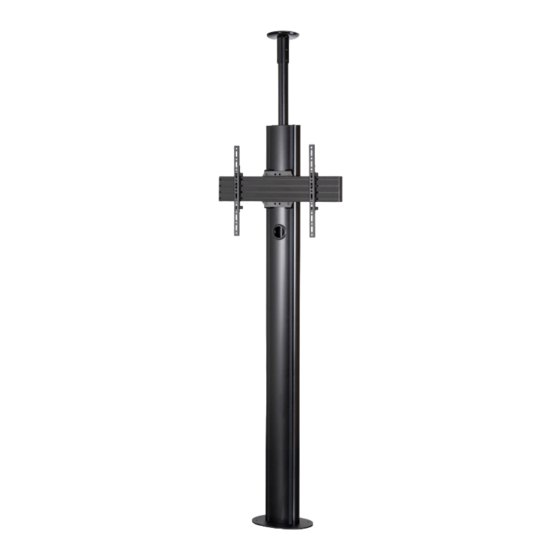
BT8702
PREMIUM flOOR-TO-CEILING
SINGLE SCREEN UC STAND
INSTALLATION GUIDE
SPECIFICATIONS
• Recommended for screens up to: 70" (177cm)
• Max load: 70kg (154lbs)
• Suitable for displays with VESA
• Universal design suitable for displaying screens
in a landscape or portrait orientation
• Integrated cable management
®
& non-VESA
www.btechavmounts.com
Advertisement
Table of Contents

Related Manuals for B-Tech BT8702


Summary of Contents for B-Tech BT8702
- Page 1 BT8702 PREMIUM flOOR-TO-CEILING SINGLE SCREEN UC STAND INSTALLATION GUIDE SPECIFICATIONS • Recommended for screens up to: 70" (177cm) • Max load: 70kg (154lbs) ® • Suitable for displays with VESA & non-VESA • Universal design suitable for displaying screens in a landscape or portrait orientation •...
- Page 2 Please check carefully to make sure there are no missing or defective parts - defective parts must never be used. B-Tech AV Mounts, its distributors and dealers are not liable or responsible for damage or injury caused by improper installation, improper use or failure to observe these safety instructions. In such cases, all guarantees will expire.
-
Page 4: Installation Tools Required
BT8702 PARTS LIST PLEASE KEEP THIS FOR FUTURE REFERENCE OPTIONAL NOT REQUIRED INSTALLATION TOOLS REQUIRED Drill Pencil Crosshead screwdriver Spanner Drill bit Pliers/Cutter... -
Page 5: Mounting Rail
ITEM PART DESCRIPTION CEILING PLATE M8 x 60mm HEX SOCKET SCREW M8 x 8mm GRUB SCREW CEILING PLATE COVER M8 x 12mm HEX SCREW 4AF HEX KEY 5AF HEX KEY EXTENSION POLE END CAP (NOT REQUIRED) COLLAR EXTENSION BAR (OPTIONAL) END CAP 3AF HEX KEY COLUMN... - Page 6 OPTIONAL EXTENDING THE COLUMNS COMBINING COLUMNS i. On the front of item D1, fix 2 x item C2 into the top of the column and tighten the bottom 2 grub screws. ii. Slide the top item D1 onto item C2, and fix the remaining 2 grub screws on item C2. EXTENSION BARS GRUB...
-
Page 7: Installation Instructions
INSTALLATION INSTRUCTIONS INSERT COLLARS TO TOP OF COLUMN Insert both items C1 into the rear slots on item D1 (Note: Ensure nuts slide into the slots). Set item C1 50mm apart and from the top of item D1. REAR SLOT REAR SLOT Ensure nuts slide into slots... - Page 8 ATTACH MOUNTING BRACKET TO COLUMN i. Insert 4 x item F2 into item F1 and attach item F3. Screw two full turns to leave item F3 at the end of item 2. M6 x 40mm RECTANGLE CSK HEX SCREW ii. Slide item F1 down the front slots of item D1 to the correct height and tighten items F2. SLOTS...
- Page 9 FIX END CAP TO COLUMN Attach item C2 to the top of item D1 using item D4. M6 x 12mm HEX SCREW ATTACH POLE TO CEILING PLATE i. Insert item B1 into item A1 and secure in place using item A2. ii.
- Page 10 INSERT POLE INTO COLUMN Pole inserted into column Insert item B1 into item D1 through items C1 & C3. Note: Keep loose, do not fix. BOLT STAND TO THE FLOOR Pre-drill holes in floor and using suitable ground anchor fixings (not supplied), fix stand to floor. GROUND ANCHOR GROUND ANCHORS (not supplied)
- Page 11 FIX TO CEILING i. Extend item B1 to mark and drill holes in the ceiling for item A1. Secure item B1 in place using the grub screws on item C1, then fix item A1 to ceiling (fixings not supplied). CEILING GRUB SCREWS Extend pole to ceiling...
- Page 12 HOOK RAIL ONTO MOUNTING BRACKET i. Insert 4 x item F4 into item G1 (2 in the top channel, 2 in the bottom channel). ii. Screw 2 x item F5 into item F4 in the top channel - allow at least a 6mm gap M8 x 12mm SLIDING INSERT HEX SCREW...
- Page 13 ATTACH INTERFACE ARMS TO SCREEN Fix item H1 to the rear of the screen using items H3 - H15. Note: Ensure the arms are facing the correct way round and the same holes are used on both arms. H3-H11 SCREEN Use spacers (items H13-H15) for screens with recessed fixings.
- Page 14 ATTACH REAR COVER AND STRIPS i. After the display has been mounted attach item D2 to the back of item D1. ii. Insert item D7 to the front and back of item D1. Note: Item D7 may have to be cut down to size to be able to fit into the front of item D1.
-
Page 15: Front View
MAX 672mm 79.5mm 8.4mm 60.8mm 310mm 210mm TOP VIEW BOTTOM VIEW 10.5mm 150mm 60mm 705mm 115mm 10.5mm 230mm THESE INSTRUCTIONS ARE INTENDED AS A GUIDE ONLY AND B-TECH ACCEPTS NO LIABILITY FOR THE ACCURACY OF THE INFORMATION CONTAINED IN THIS DOCUMENT. - Page 16 ©2020 B-Tech AV Mounts. All rights reserved. B-Tech AV Mounts is a division of B-Tech International Design and Manufacturing Ltd. B-Tech AV Mounts and the B-Tech logo are registered trade marks. All other brands and product names are trademarks of their respective owners.
Need help?
Do you have a question about the BT8702 and is the answer not in the manual?
Questions and answers