Table of Contents
Advertisement
Quick Links
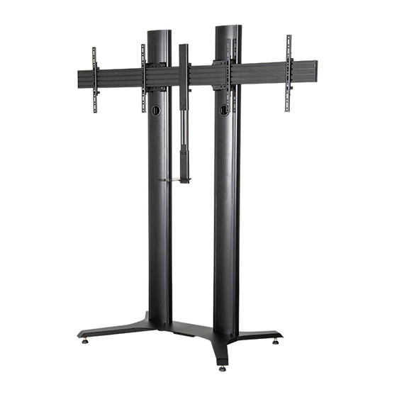
BT8712
PREMIUM FREESTANDING
TWIN SCREEN VC STAND
INSTALLATION GUIDE
SPECIFICATIONS
• Recommended for screens: 46" - 65" (117 - 165cm)
• Max load: 56kg (123lbs) per screen
• Suitable for displays with fixings up to 600 x 400mm
• Stand dimensions: H.1945 x W.2005 x D.757mm
• Integrated cable management
www.btechavmounts.com
65"
165
CM
PER SCREEN
Advertisement
Table of Contents

Related Manuals for B-Tech BT8712


Summary of Contents for B-Tech BT8712
- Page 1 BT8712 PREMIUM FREESTANDING TWIN SCREEN VC STAND INSTALLATION GUIDE SPECIFICATIONS • Recommended for screens: 46" - 65" (117 - 165cm) • Max load: 56kg (123lbs) per screen • Suitable for displays with fixings up to 600 x 400mm 65" • Stand dimensions: H.1945 x W.2005 x D.757mm •...
-
Page 2: Installation Safety Instructions
Please check carefully to make sure there are no missing or defective parts - defective parts must never be used. B-Tech AV Mounts, its distributors and dealers are not liable or responsible for damage or injury caused by improper installation, improper use or failure to observe these safety instructions. In such cases, all guarantees will expire. -
Page 4: Installation Tools Required
BT8712 PARTS LIST PLEASE KEEP THIS FOR FUTURE REFERENCE INSTALLATION TOOLS REQUIRED 13mm Spanner Crosshead screwdriver Pliers/Cutter... - Page 5 ITEM PART REF DESCRIPTION 1.9M COLUMN END CAP COLUMN REAR COVER M6 x 12mm HEX SCREW M6 x 12mm GRUB SCREW (OPTIONAL) SQUARE NUT (OPTIONAL) COVER STRIP 3AF HEX KEY 4AF HEX KEY BASE - LEFT SIDE BASE - RIGHT SIDE BASE CONNECTOR ADJUSTABLE LEVELLING FEET M6 x 30mm CSK HEX SCREW...
-
Page 6: Installation Instructions
Installation Instructions ASSEMBLE BASE i. Fix item B1 to item B2 using items B3 & B6 on the front and back. M10 x 25mm HEX SCREW ii. Screw item B4 into items B1 & B2. - Page 7 OPTIONAL - FIX REAR COVERS TO COLUMNS Place item A3 into the back of item A1. Use items A5 & A6 at the top and bottom M6 x 12mm SQUARE of the column slot to secure rear cover. GRUB SCREW REAR REAR ATTACH COLUMNS TO BASE...
- Page 8 ATTACH MOUNTING BRACKETS TO COLUMNS i. Insert 4 x item C2 into item C1 and attach item C3. Screw two full turns to leave item C3 at the end of item C2. M6 x 40mm RECTANGLE Repeat for all 4 mounting plates. CSK HEX SCREW ii.
- Page 9 HOOK RAIL ONTO MOUNTING BRACKET i. Insert 4 x item C4 into item D1 (2 in the top channel, 2 in the bottom channel) on each side of the rail. M8 SLIDING M8 x 12mm ii. Screw 2 x item C5 into item C4 in the top channel - allow at least a 6mm gap HEX SCREW INSERT so the rail can be hooked on to item C1.
- Page 10 ASSEMBLE VC SHELF i. Attach item G2 to item G1 using items G5 & G6. ii. Attach item G10 to item G2. using items G7 & G8. M8 x16mm M8 NYLOC M8 METAL M8 SPRING WASHER HEX SCREW WASHER 13mm Spanner Note: The shelf adaptor can mount the shelf above or below the screens.
- Page 11 HOOK SHELF ONTO MOUNTING RAIL i. Hook item G1 onto item D1. ii. Secure shelf to rail. Use item G4 on the bottom of item G1 to secure the shelf to item D1. Optional: Level the shelf bracket by adjusting item G4 on top of item G1.
- Page 12 ATTACH INTERFACE ARMS TO SCREENS Fix item E1 to the rear of the screens using items E3 - E15. Note: Ensure the arms are facing the correct way round and the same holes are used on all arms. 600mm ADAPTOR ARMS Note: Use (if required) for 65”screens with VESA 600 x 400mm fixings i.
-
Page 13: Attach Camera
LOCK SCREENS TO RAIL ATTACH CAMERA TO SHELF Tighten the safety screws on the bottom Fix camera to item G10 using of item E1 securing the screens to item D1. M4 x 10mm either item G11 or item G12. Note: If necessary, adjust the height adjustment SCREW screws on top of item E1 to level the screen. -
Page 14: Front View
BT8712 DIMENSIONS PLEASE KEEP THIS FOR FUTURE REFERENCE FRONT VIEW 180mm 8.4mm 400mm 60.8mm TOP VIEW 2005mm 100mm These instructions are intended as a guide only and B-Tech accepts no liability for the accuracy of the information contained in this document. -
Page 15: Side View
PLEASE KEEP THIS FOR FUTURE REFERENCE 79.5mm 253.1mm SIDE VIEW BOTTOM VIEW 1127.7mm 1029.1mm 70mm 40mm 506mm 973mm These instructions are intended as a guide only and B-Tech accepts no liability for the accuracy of the information contained in this document. - Page 16 ©2020 B-Tech AV Mounts. All rights reserved. B-Tech AV Mounts is a division of B-Tech International Design and Manufacturing Ltd. B-Tech AV Mounts and the B-Tech logo are registered trade marks. All other brands and product names are trademarks of their respective owners.
Need help?
Do you have a question about the BT8712 and is the answer not in the manual?
Questions and answers