Table of Contents
Advertisement
Quick Links
Advertisement
Table of Contents

Subscribe to Our Youtube Channel
Related Manuals for Columbus McKinnon Entertainment-Lodestar B


Summary of Contents for Columbus McKinnon Entertainment-Lodestar B
- Page 1 ® Operating, Maintenance & Parts Manual 1/4 Tonne To 2 Tonne 250 kg To 2000 kg Columbus McKinnon Corporation CM Entertainment 140 John James Audubon Parkway Amherst, New York 14228-1197 1-800-888-0985 1-716-689-5400 www.CM-ET.com 00000999 (REV AB) E627NH...
- Page 2 CM HOIST PARTS AND SERVICES ARE AVAILABLE IN THE UNITED STATES AND IN CANADA PARTS FOR YOUR HOIST ARE AVAILABLE FROM YOUR LOCAL AUTHORIZED REPAIR STATION. FOR THE NAME OF THE NEAREST PARTS OR SERVICE CENTER, VISIT OUR WEB SITE WWW.CMWORKS.COM OR CALL OUR CUSTOMER SERVICE DEPARTMENT.
-
Page 3: Safety Precautions
CM industrial hoists. For such applications, refer to the requirements of applicable state and local codes, and the American National Safety Code for elevators, dumbwaiters, escalators and moving walks (ASME A17.1). Columbus McKinnon Corporation cannot be responsible for applications other than those for which CM equipment is intended. -
Page 4: Table Of Contents
FOREWORD This manual contains important information to help you properly install, operate and maintain your hoist for maximum performance, economy and safety. Please study its contents thoroughly before putting your hoist into operation. By practicing correct operating procedures and by carrying out the recommended preventive maintenance suggestions, you will experience long, dependable and safe service. After you have completely familiarized yourself with the contents of this manual, we recommend that you carefully file it for future reference. -
Page 5: Specifications
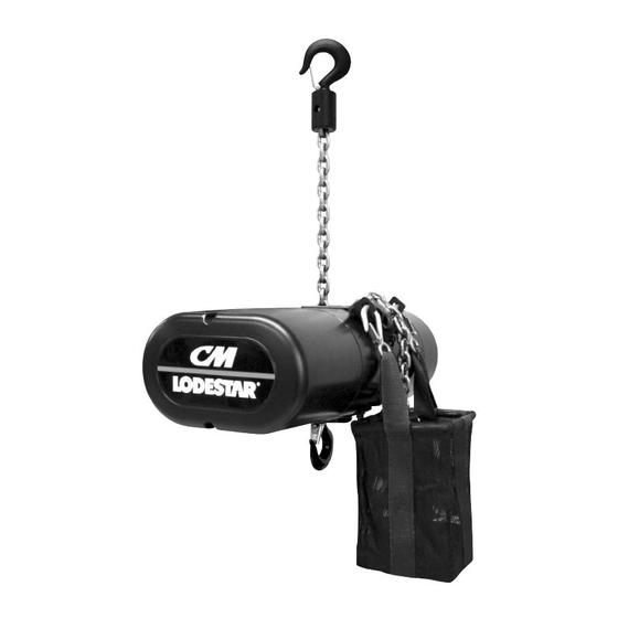
SPECIFICATIONS The Lodestar Electric Chain Hoist is a highly versatile materials Retain this manual for future reference and use. handling device that can be used to lift loads that are within Forward this manual to the hoist operator. its rated capacity. The mechanical features of these hoists Failure to operate the equipment as directed in the manual include an alloy liftwheel, load-limiter, hardened steel chain may cause injury. -
Page 6: Installation
INSTALLATION UNPACKING INFORMATION The dead end of the load chain is temporarily positioned When received, the hoist should be carefully inspected for (a few links from the end) by a wire tie. Do not remove this tie damage which may have occurred during shipment or han- before attaching the chain to the dead end block. -
Page 7: Attaching Load Chain
ATTACHING LOAD CHAIN The Double Reeved Units are shipped with the dead end of the load chain temporarily connected to the bottom of the hoist by a wire tie (1) as shown in Figure 7. The wire tie is located a few links from the end of the chain, and it should Figure 7. -
Page 8: Power Supply And Electrical Connections
POWER SUPPLY AND ELECTRICAL CONNECTIONS The hoist should be connected to a branch circuit which complies with the requirements of the National Electrical Code and applicable local codes. It is recommended, especially for a single phase hoist with a (1) horsepower motor (.75 Kilowatts), that a line of adequate capacity be run directly from the power supply to the hoist to prevent problems with low voltage and circuit overloads. - Page 9 WARNING WARNING Failure to properly ground the hoist presents the danger of Allowing the hook block to run into the bottom of the hoist electric shock. when raising a load or allowing the chain to become taut between the loose end screw and the frame when lowering TO AVOID INJURY: a load may break the chain and allow the load to drop.
-
Page 10: Operating Instructions
CHECKING LIMIT SWITCH OPERATION IF HOIST IS OPERATING INSTRUCTIONS EQUIPPED With hoists that are equipped with an adjustable screw limit switch, the limit switch will automatically stop the hook at GENERAL any predetermined point when either hoisting or lowering. 1. The Load-limiter is designed to slip on an excessive over- load. -
Page 11: Inspection
9. Warn personnel of your intention to lift a load in the area. INSPECTION Tie off the load with auxiliary chains or cables before access to the area beneath the load is permitted. 10. Do not operate hoist at unusual extremes of ambient To maintain continous and satisfactory operation, a regular temperatures above 150º... -
Page 12: Minimum Frequent Inspections
Table 4. Minimum Frequent Inspections TYPE OF SERVICE ITEM Normal Heavy Severe a) Brake for evidence of slippage. b) Control functions for proper operation. c) Hooks for damage, cracks, twists, excessive throat opening, latch engagement and latch operation - see page 10. d) Load chain for adequate lubrication, as well as for signs of wear, damaged links or foreign matter - see page 10. -
Page 13: Load Chain
LATCH TYPE HOOK LATCHLOCK TYPE HOOK ® (Upper and Lower) (UPPER AND LOWER) TO MEASURE OPENING, “A” Max. DEPRESS LATCH AGAINST HOOK BODY AS SHOWN. “B” Max. Replace Hooks Replace Hook When Opening Models When Opening Models is Greater Than or Seat are: 1 3/16 in. -
Page 14: Maintenance
MAINTENANCE LOAD-LIMITER BEARINGS The Load-limiter should operate for the normal life of the • All bearings and bushings, except the lower hook thrust hoist without service. The device has been calibrated at the bearing, are pre-lubricated and require no lubrication. factory for a specific model of hoist. -
Page 15: Limit Switches
LIMIT SWITCH ADJUSTMENT SETTING UPPER LIMIT SWITCH After completing steps1 thru 4 If limit switch operation has been checked as described on page 7 and is not operating correctly or is not automatically 5. Refer to table 6 - The "A" Dimensions given are the minimum stopping the hook at a desired position, proceed as follows: distance that should be set between the top hook block and the bottom of the hoist. - Page 16 CONVERTING LIMIT SWITCH GUIDES 10.Securely reposition the guide plate in the slot 1. Disconnect the hoist from the power supply system. 11.Reconnect hoist to power supply and check the stopping 2. Refer to the exploded views and remove the back frame cover point of hook by first lowering the hook about 2 feet from the hoist.
-
Page 17: Electrical Data
ELECTRICAL DATA TO DETECT OPEN AND SHORT CIRCUITS IN ELECRICAL COMPONENTS Open circuits in the coils of electrical components may be detected by isolating the coil and checking for continuity with an ohmmeter or with the unit in series with a light or bell circuit. Shorted turns are indicated by a current draw substantially above normal (connect ammeter in series with suspected element and impose normal voltage) or D.C. -
Page 18: Troubleshooting
TROUBLE SHOOTING All Hoists Table 8. TROUBLE PROBABLE CAUSE CHECK AND REMEDY 1. Hook does not respond A.) No voltage at hoist-main line or branch A.) Close switch, replace fuse or reset to the control station or circuit switch open; branch line fuse breaker. - Page 19 TROUBLE PROBABLE CAUSE CHECK AND REMEDY 4.) Hook raises but will not A.) Open lowering circuit-open or shorted A.) Check electrical continuity and repair or lower. winding in reversing contactor coil, loose replace defective part. Check operation of connection or broken wire in circuit; limit switch as described on page 12.
-
Page 40: Assembly Instructions
ASSEMBLY INSTRUCTIONS WARNING The suspension screws are special high strength screws and under no circumstances should screws other than these be used to attach the supsension to the hoist. If other than the supplied, high strength screws are used, they may break and allow the hoist to fall from the support UNDER SIDE OF 5.45 in SUSPENSION... -
Page 41: Lower Hook Block Pin
FASTENERS See tables 2a and 2b for recommended torque values. LOWER HOOK BLOCK PIN When removing or installing the lower hook pin, care must be taken so as to prevent damaging the pin and/or hook block. These pins are tapered groove pins and as a result, they can only be removed in one direction. -
Page 42: Removal And Installation Of Load Chain
REMOVAL AND INSTALLATION OF LOAD f) Reassemble hoist with the new load chain inserted over the liftwheel. Position chain with the weld on CHAIN upstanding links away from liftwheel and leave only one foot of chain hanging free on loose end side. WARNING On double reeved models, make certain that the new load chain is free of twists. -
Page 43: Cutting Chains
CUTTING CHAIN WARNING ® Load chain is hardened and it is difficult to cut. The following methods are recommended when cutting a length TESTING OF MECHANICAL of new chain from stock or cutting off worn chain. OVERLOAD PROTECTION 1. Use a grinder and nick the link on both sides (Figure Before using, all altered, repaired or used hoists that have 23), then secure the link in a vise and break off with not been operated for the previous 12 months shall be... - Page 49 NOTES...
- Page 54 1.2.1 1.2.1 1.11 1.11 1.11 1.11 1.10 1.10 RIGID HOOK ASSEMBLY SWIVEL HOOK ASSEMBLY V1-SMALL FRAME V2-LARGE FRAME PART NUMBERS PART NUMBERS ITEM NO. DESCRIPTION QTY. MODELS MODELS MODELS B, C & F J, L & LL R & RR SWIVEL SUSPENSION ASSEMBLY - W/ LATCH TYPE 2792NH 3661NH...
- Page 55 V1-SMALL FRAME V2-LARGE FRAME COMPONENT COMPONENT PART NUMBERS PART NUMBERS ITEM NO. DESCRIPTION QTY. MODEL MODEL MODEL MODEL MODEL MODELS B, C & F EXTERNAL CHAIN GUIDE KIT - W/ BAG 00000558 00000559 BRACKET EXTERNAL CHAIN GUIDE KIT - W/O BAG 00000560 00000561 BRACKET...
- Page 56 1.1.1 SINGLE-REEVED MODELS ITEM NO. DESCRIPTION QTY. B, C & F J, L & LL LOWER HOOK BLOCK ASSEMBLY-COMPLETE WITH LATCH *28683 *35651 TYPE HOOK LOWER HOOK WITH LATCH 28686 35611 LATCHLOK TYPE HOOK 28604 28604 1.1.1 LATCH KIT 45661 45662 LOWER HOOK BODY 45401B...
- Page 57 1.1.3 1.1.2 1.1.1.1 1.1.4 1.1.1 MODELS ITEM NO. DESCRIPTION QTY. R & RR LOWER HOOK BLOCK ASSEMBLY-COMPLETE WITH *00000277B LATCH TYPE HOOK LOWER HOOK ASSEMBLY WITH LATCH AND BRG 35645 LATCHLOK TYPE HOOK ASSEMBLY WITH BRG LOWER HOOK WITH LATCH 35612B 1.1.1 LATCHLOK TYPE HOOK...
- Page 58 BACK FRAME w/ DRIVE SHAFT ASSEMBLED VIEW BRAKE ASSEMBLY BRAKE COIL HOIST MOTOR ITEM 1 VOLTAGE 00001400 110/115-1-50/60 103VDC 220/230-1-50/60 00001401 220/230-3-50/60 205VDC 380/415/480-3-50/60 ITEM NO. PART NUMBER DESCRIPTION QTY. SEE TABLE V1 LODESTAR SIZE 8 00001427 V1 LODESTAR, SIZE 8 ROTOR 00001430 V1 LODESTAR, SIZE 8 HUB 00001432...
- Page 59 BACK FRAME w/ DRIVE SHAFT ASSEMBLED VIEW BRAKE ASSEMBLY ROTOR BRAKE COIL HOIST MODEL HOIST MOTOR ITEM 1 ITEM 1.1 VOLTAGE 110/115-1-50/60 00001406 00001428 103VDC 220/230-1-50/60 J, L, R 220/230-1-50/60 00001407 00001428 220/230-3-50/60 205VDC 380/415/480-3-50/60 220/230-3-50/60 LL, RR 00001413 00001429 205VDC 380/415/480-3-50/60 ITEM NO.
- Page 60 BACK FRAME w/ DRIVE SHAFT ASSEMBLED VIEW BRAKE ASSEMBLY BRAKE COIL HOIST MOTOR ITEM 1 VOLTAGE 220/230-1-50/60 00001404 220/230-3-50/60 205VDC 380/415/480-3-50/60 ITEM NO. PART NUMBER DESCRIPTION QTY. SEE TABLE V1 LODESTAR, SIZE 8 DOUBLE 00001427 V1 LODESTAR, SIZE 8 ROTOR 00001430 V1 LODESTAR, SIZE 8 HUB 982708...
- Page 61 BACK FRAME w/ DRIVE SHAFT ASSEMBLED VIEW BRAKE ASSEMBLY ROTOR BRAKE COIL HOIST MODEL HOIST MOTOR ITEM 1 ITEM 1.1 VOLTAGE 220/230-1-50/60 J, L, R 00001410 00001428 220/230-3-50/60 205VDC 380/415/480-3-50/60 220/230-3-50/60 00001416 LL, RR 00001429 205VDC 380/415/480-3-50/60 ITEM NO. PART NUMBER DESCRIPTION QTY.
- Page 62 BACK FRAME w/ DRIVE SHAFT AND SINGLE DC BRAKE ASSEMBLED VIEW BRAKE ASSEMBLY BRAKE COIL HOIST MOTOR ITEM 1 VOLTAGE 00001418 110/115-1-50/60 103VDC 220/230-1-50/60 00001419 220/230-3-50/60 205VDC 380/415/480-3-50/60 ITEM NO. PART NUMBER DESCRIPTION QTY. SEE TABLE V1 LODESTAR, SIZE 8 00001427 V1 LODESTAR, SIZE 8 ROTOR 00001430...
- Page 63 BACK FRAME w/ DRIVE SHAFT AND SINGLE DC BRAKE ASSEMBLED VIEW BRAKE ASSEMBLY ROTOR BRAKE COIL HOIST MODEL HOIST MOTOR ITEM 1 ITEM 1.1 VOLTAGE 00001421 00001428 110/115-1-50/60 103VDC J, L, R 220/230-1-50/60 00001422 00001428 220/230-3-50/60 205VDC 380/415/480-3-50/60 220/230-1-50/60 LL, RR 00001425 00001429 220/230-3-50/60...
- Page 64 BACK FRAME w/ DRIVE SHAFT ASSEMBLED VIEW BRAKE ASSEMBLY BRAKE COIL FRICTION INTERMEDIATE HOIST ITEM 1 ITEM 1.9 DISC PLATE MODEL ITEM 1.3 ITEM 1.7 115V COIL 230V COIL 115V 230V 27656 27659 27677 (x1) NOT REQ'D 51517 51518 C & F 27681 27684 27677 (x2)
- Page 65 BACK FRAME w/ DRIVE SHAFT ASSEMBLED VIEW BRAKE ASSEMBLY BRAKE COIL SPRING ITEM 1 ITEM 1.3 HOIST MODEL ITEM 1.9 115V COIL 230V COIL 460V COIL 115V 230V 460V J, L, R 35646 35647 35622 51510 51511 51513 35716 35648 35623 51512 51514...
- Page 74 1.16 1.18 1.15 1.20 1.12 1.19 1.13 1.17 1.10 1.14 CONTACTOR REVERSING SECONDARY 1.11 BKT S/A CONTACTOR VOLTAGE 00000300 28860 24 V 00000301 24797 48 V 00000302 24799 110 V ITEM NO. PART NUMBER DESCRIPTION QTY. SEE TABLE CONTACTOR BKT S/A BHSE 29010 DIN-RAIL 6.50"...
- Page 75 ITEM NO. PART NUMBER DESCRIPTION QTY. 27700 6 POLE TERMINAL STRIP 27704 Terminal Strip Bracket 27709 Mounting Bracket Spacer 987929 LOCKWASHER #5 REG. HELICAL 982718 MACHINE SCREW PAN HEAD 982226 LOCKWASHER 1/4 X .109 X .062" 987395 MACHINE SCREW SLOTTED FIL HD V1 CONTACTOR PLATE ASSEMBLY FOR USE WITH AC BRAKE DIRECT CONTROL...
- Page 76 1.20 1.11 1.21 1.15 1.16 1.17 1.14 1.18 1.19 1.24 1.10 1.23 1.22 1.13 1.12 ITEM NO. PART NUMBER DESCRIPTION QTY. 29917 CONTACTOR PLATE SUB-ASSEMBLY 31633 CONTACTOR PLATE 29312 DIN-RAIL 5.00" LONG 29014 TERMINAL STRIP 29015 TERMINAL STRIP END CLAMP 24799 REVERSING CONTACTOR 110V 982686...
- Page 77 1.17 1.15 1.18 1.14 1.16 1.11 1.10 1.13 CONTACTOR REVERSING SECONDARY 1.12 BKT S/A CONTACTOR VOLTAGE 00000303 28860 24 V 00000304 24797 48 V 00000305 24799 110 V ITEM NO. PART NUMBER DESCRIPTION QTY. SEE TABLE CONTACTOR BKT S/A BHSE NA 29010 DIN-RAIL 6.50"...
- Page 78 1.14 1.16 1.17 1.18 1.12 1.10 1.11 1.19 1.22 1.21 1.20 1.15 1.13 CONTACTOR TRANSFORMER REVERSING SECONDARY BKT S/A CONTACTOR VOLTAGE 00000340 00000594 28860 24 V 00000341 00000595 24797 48 V 00000342 00000596 24799 110 V ITEM NO. PART NUMBER DESCRIPTION QTY.
- Page 79 ITEM NO. PART NUMBER DESCRIPTION QTY. 00000346 TERMINAL BRKT S/A 00000278 CONTACTOR BRACKET 27700 6 POLE TERMINAL STRIP 982718 MACHINE SCREW PAN HEAD 987929 LOCKWASHER #5 REG. HELICAL V2 CONTACTOR PLATE ASSEMBLY FOR USE WITH AC BRAKE DIRECT CONTROL 220/230-380/415/460-3-50/60 MODELS J, L, LL, R, &...
- Page 80 1.15 1.11 1.19 1.20 1.17 1.16 1.18 1.12 1.14 1.13 1.10 ITEM NO. PART NUMBER DESCRIPTION QTY. 00000347 CONTACTOR BKT S/A 1Ø V2 00000278 CONTACTOR BRACKET 35268 CLAMP 982873 MACHINE SCREW PAN HEAD 35279 START CAPACITOR 35285 RUNCAPACITOR INSULATOR 35278 CAPACITOR, RUN 20940 GROUND LABEL...
- Page 81 1.17 1.19 1.13 1.16 1.11 1.10 1.15 1.20 1.18 1.14 1.12 CONTACTOR TRANSFORMER REVERSING SECONDARY BKT S/A CONTACTOR VOLTAGE 00000343 00000594 28860 24 V 00000344 00000595 24797 48 V 00000345 00000596 24799 110 V ITEM NO. PART NUMBER DESCRIPTION QTY. SEE TABLE CONTACTOR BKT S/A BHSE NA 00000278...
-
Page 82: Recommended Spare Parts
LUBRICANTS Part Number for Packaged Lubricants Used in the Lodestar Electric Chain Hoists (Refer to page 11 for Lubrication Instructions) Part Numbers and Lubricant Type of Packaged Quantity of Usage Lubricant Lubricants Grease Contact Factory Hoist Gears (Special) 28608 for 1 Pint Can Load Chain 28619 for 1 Gal Can Limit Switch... -
Page 84: General Information
GENERAL INFORMATION All Columbus McKinnon (CM ) Lodestar Electric Chain We reserve the right to change materials or design, if, in our Hoists are thoroughly inspected and performance tested opinion, such changes will improve our product. Abuse, prior to shipment. If any properly maintained hoist develops... - Page 85 ORIGINELE VERKLARING VAN OVEREENSTEMMING Volgens Annex IIA van machinerichtlijn (2006/42/EG) Louis Reyners B.V. Symon Spiersweg 13A 1506 RZ Zaandam Nederland Hierbij verklaren wij, Louis Reyners dat de onderstaande producten vanaf het bouwjaar 2009: CM Lodestar elektrische kettingtakels voor een draaglast van 0,125t tot 3t Voldoen aan onderstaande richtlijnen zoals bekend gemaakt in het Publicatieblad van de Europese Unie: EG-machinerichtlijn 2006/42/EG...
Need help?
Do you have a question about the Entertainment-Lodestar B and is the answer not in the manual?
Questions and answers