
Subscribe to Our Youtube Channel
Related Manuals for Dover Dow-Key Microwave 3205


Summary of Contents for Dover Dow-Key Microwave 3205
- Page 1 Model 3205 Solid State Matrix System Operation Manual Document No. 49101-130 Rev. 1...
- Page 2 Copyright Dow-Key Microwave Corporation 2004, All rights reserved. Information in this publication supercedes that in all previously published material. Specifications and price change privileges reserved. Printed in the U.S.A. Dow-Key is a registered trademark of Dow-Key Microwave Corp.
- Page 3 WARRANTY Dow-Key Microwave Corporation warrants this product to be free from defects in material and workmanship for a period of 1 year from date of shipment. This warranty does not apply to defects resulting from product tampering or modification without Dow- Key’s express written consent.
- Page 4 Manual Revision History The revision history shown below lists of all revisions and addendums created for this manual. The revision level increases numerically as the manual undergoes subsequent updates. Addendums are released between revisions and contain important change information that the user should incorporate immediately into the manual. When a new revision is created, all addendum associated with the previous revision of the manual are incorporated into the new revision of the manual.
-
Page 5: Table Of Contents
Table of Contents General Information Introduction ………………………………………………………………………… 1 Specifications ……………………………………………………………………. 1 Safety Precautions ……………………………………………………………….. 2 Inspection …………………………………………………………………………. 2 Maintenance ……………………………………………………………………. 3 Repacking for Shipment ………………………………………………………….. 3 System Layout Front Panel Layout …………………………………………………………….…. 4 Rear Panel Layout ……………………………………………………………….. 5 Schematic Layout ……………………………………………………………..…... - Page 6 Table of Contents Remote Operation Introduction …………..……………………………………………………………… 22 Shortcuts …………………….……………………………………………………. 22 Route:Pathx y ………….…………………………………………………………. 22 Route:Pathy? …………..…………………………………………………………. 23 Route:Path All? ……………………………………………………………………. 23 *IDN? ………………………………………………………………………………. 23 System:Softreset ……………………………………………………………….. 24 System:Hardreset ………………………………………………………………… 24 System:Error? ………………………………………………………………………24 List of Figures Front Panel Layout …………………………………………………………….….. 4 Rear Panel Layout …………………………………………………………….…..
-
Page 7: General Information
General Information Introduction The Dow-Key Microwave Model 3205 is a 6 x 12 full fan-out non-blocking solid state matrix that can connect any input to any one or multiple outputs using BNC female connectors on the inputs and outputs. The Model 3205 comes complete with a state of the art graphical touch screen display for manual operation which allows the user to easily connect an output to an input with a touch of the screen. -
Page 8: Safety Precautions
General Information Operating Temp: 0° to +55° degrees C Line Voltage: 120-240 VAC, 50-60 Hz, 3-6A, 200W max Remote Control Interface: Ethernet 10BT/100/100BT with RJ-45 Connector RS-232 with DB9 Female Connector Local Control: 6.4” VGA TFT LCD Touch Screen Operating System: Microsoft®... -
Page 9: Maintenance
General Information Maintenance The Model 3205 requires no periodic maintenance. Should any problems arise, contact Dow-Key Microwave immediately for necessary repairs. This system is not field repairable. Repacking for shipment Should it become necessary to return the Model 3205 for repair, carefully pack the unit in its original packing carton or the equivalent, and follow these instructions: •... -
Page 10: System Layout
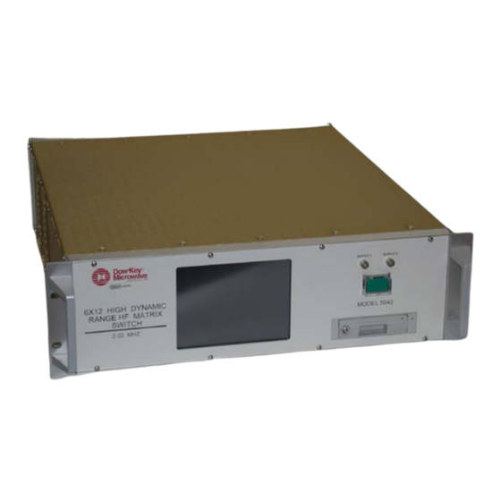
• Power Switch with a switch guard Figure 2-1 Power Switch LED’s for Power Front Panel Layout with Guard Supply Monitoring Dow-Key SUPPLY 1 SUPPLY 2 Microwave CORPORATION DOVER COMPANY 6X12 HIGH DYNAMIC RANGE HF MATRIX SWITCH MODEL 5042 2-32 MHZ Touch Screen Removable Hard Drive... -
Page 11: Rear Panel Layout
System Layout Rear Panel Layout Figure 2-2 shows the general layout of the rear panel of the Model 3205 which includes: • BNC-Precision Female Connectors • Power Entry Module with built in Fuse • RJ-45 Connector • DB9 Female Connector •... -
Page 12: Schematic Layout
System Layout Schematic Layout Figure 2-3 Simplified Schematic OUT 1 OUT 2 OUT 3 IN 1 OUT 4 IN 2 OUT 5 IN 3 OUT 6 IN 4 OUT 7 IN 5 OUT 8 IN 6 OUT 9 OUT 10 OUT 11 OUT 12... -
Page 13: Connections
Connections Power Connections 3.1.1 Line Voltage – The Model 3205 operates from a line voltage in the range of 120V to 240V at a frequency of 50 or 60Hz. Line voltage selection is automatic. CAUTION: Operating the unit on an incorrect line voltage may cause damage, possibly voiding the warranty. -
Page 14: Ground Connection
Connections Figure 3-1 Power Entry Module Insert small bladed screwdriver on both sides to release the fuse. DISCONNECT POWER BEFORE REPLACING FUSES Table 3-1 Line Fuse Line Fuse Rating Manufacturer Manufacturer Part No. Voltage 120-240V 2A, Slo-Blo, 250V, ¼” x 1-1/4” Littelfuse 312002 Ground Connection... -
Page 15: Configuring The Matrix
Configuring the Matrix Configuring the Matrix Before you configure your matrix, you will need to contact your network administrator to obtain the following information: • an IP address for the matrix • TCP port number Each device on your network must have a unique address so that all devices can communicate simultaneously over the same network. -
Page 16: Turning On The Unit
Configuring the Matrix Turning on the Unit To turn on your matrix lift up the switch guard on the front panel and press the green button. The button will illuminate green and the LCD will also illuminate and Microsoft® Windows® 2000 Professional will start to load. Calibrating the Touch Screen To calibrate the touch screen use the stylus that was provided with the unit and click on the program “Cybertouch”. -
Page 17: Communication Problems
Configuring the Matrix Communication Problems Your Matrix interface does not need or include any proprietary driver software. It was designed to operate with common network utilities and drivers. If the Matrix fails to communicate, contact your network administrator for additional assistance. -
Page 18: Manual (Local) Operation
Manual (LOCAL) Operation Front Panel Controls Once the unit has booted up to the windows screen. Click onto the “DOW-KEY MICROWAVE” ICON. The display will show a grid with Outputs 1 through 12 on the left and Inputs 1 through 6 along the bottom as shown in Figure 5-1. Figure 5-1 Start-up display... -
Page 19: Manual Operation Using The Touch Screen
Manual (LOCAL) Operation Manual Operation using the Touch Screen Manual mode of operation for the Model 3205 is facilitated by using the front panel 6.4” VGA TFT LCD touch screen. To connect a path click on which output you desire then click on the input path you desire. A line will appear showing the connection you requested. -
Page 20: Setting Multiple Outputs To A Single Input
Manual (LOCAL) Operation Setting Multiple Outputs to a Single Input You may connect multiple outputs to a single input. Lets say you also want to set output 2 to input 3 and output 8 to input 3. Using the say procedure as stated in 5.2 first click onto output 2 and then input 3 followed by clicking on output 8 to input 3. -
Page 21: Disconnecting A Path
Manual (LOCAL) Operation Disconnecting a Path To disconnect a path first click on the desired output then on the desired input and the path will disconnect. Lets say you want to disconnect Output 5 from Input 3. First click on Output 5 and then on Input 3 and the path will disconnect as shown in Figure 5-4. -
Page 22: Setup
Manual (LOCAL) Operation Setup Setup is where the user can define the following parameters and as shown in Figure 5-5. 1. Change the color of the inputs 2. Reassign the Output names 3. Reassign the Input names 4. Assign a Network name and port number 5. -
Page 23: Setup - Color
Manual (LOCAL) Operation 5.6.1 Setup - Color To change the colors of the connection lines go to the setup button in the upper right hand corner. There are 8 inputs each with their own color. To change a color of an input line click on that input and choose a new color. See Figure 5-6. -
Page 24: Setup - Output
Manual (LOCAL) Operation 5.6.2 Setup – Output Names To change Output Names go to the setup button in the upper right corner of the touch screen and click on the Output Names tab. Click inside the box you wish to change and type in the new name. See Figure 5-7. Note: Maximum number of characters is 6 Figure 5-7 Change Output Names... -
Page 25: Setup - Input Names
Manual (LOCAL) Operation 5.6.3 Setup – Input Names To change Input Names go to the setup button in the upper right corner of the touch screen and click on the Input Names tab. Click inside the box you wish to change and type in the new name. -
Page 26: Setup - Network Name
Manual (LOCAL) Operation 5.6.4 Setup – Network Name To change Network Name go to the setup button in the upper right corner of the touch screen and click on the Network Name tab. It will give you the current network name and down below gives you the option to change and type in the new name. -
Page 27: Ip Address Screen
Manual (LOCAL) Operation 5.6.5 Setup - IP Address To set the IP Address click on the setup button in the upper right corner and click on the IP Address tab. There are two network settings to choose from, Obtain IP Address automatically or Use an IP Address given by your network administrator. -
Page 28: Remote Operation
Remote Operation Introduction The following list of commands is what is supported by the 3205. These commands must be issued to the Ethernet interface and will not be recongnized on any other interface (i.e. RS-232 Console). All commands will return “OPC” for operation complete after the command that was set sent is completed. -
Page 29: Route:pathy
Remote Operation ROUTE:PATHy? Syntax ROUTE:PATHy? Y = Output Description This command will return the current setting for output y in the form of “PATHx,y”. x will be a number from 0-8 corresponding to the particular input with 0 meaning that it is disconnected. ROUTE:PATH ALL? Syntax ROUTE:PATH ALL? -
Page 30: System:softreset
Remote Operation SYSTEM:SOFTRESET Syntax SYSTEM:SOFTRESET Description This command is the soft reset. This will cause the unit to be forcibly reset, returning everything to the most recent mode of operation based on stored configuration information similar to power cycling. SYSTEM:HARDRESET Syntax SYSTEM:HARDRESET Description...
Need help?
Do you have a question about the Dow-Key Microwave 3205 and is the answer not in the manual?
Questions and answers