Table of Contents
Advertisement
Quick Links
DYN-6336-01
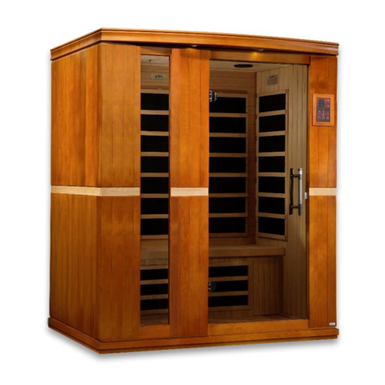
3 Person Sauna
OWNER'S MANUAL
FOR CARBON MODEL SAUNAS
FOR INDOOR USE ONLY
Requires 120V 20 AMP DEDICATED CIRCUIT
Sauna: Now you can enjoy the European secret for youthful vitality.
Carefully and thoroughly read this manual before using the sauna. We
recommend keeping this manual for regular review and future reference.
1
Advertisement
Table of Contents

Related Manuals for Dynamic Saunas DYN-6336-01


Summary of Contents for Dynamic Saunas DYN-6336-01
- Page 1 DYN-6336-01 3 Person Sauna OWNER’S MANUAL FOR CARBON MODEL SAUNAS FOR INDOOR USE ONLY Requires 120V 20 AMP DEDICATED CIRCUIT Sauna: Now you can enjoy the European secret for youthful vitality. Carefully and thoroughly read this manual before using the sauna. We...
- Page 2 WHAT ARE INFRARED RAYS? Infrared is the band of light we perceive as heat. We cannot see this band of light with the naked eye, but we can feel this type of light in the form of heat. Our sun produces most of its energy output in the infrared segment of the spectrum.
- Page 3 HOW IT WORKS Infrared Saunas differ from traditional saunas in that they use infrared radiant energy to directly penetrate into the body's tissue to produce perspiration. Traditional saunas use steam to heat the air inside the sauna, which then heats your body until you begin to perspire.
- Page 4 Benefits include, but are not limited to: - Pain relief from Rheumatoid Arthritis - Relaxing muscle spasms - Increases blood circulation - Cardiovascular conditioning - Clears rashes, acne - Reduces cellulite - Removes toxins and mineral waste - Reduces stress and fatigue - Enhances skin tone SAUNA MAINTENANCE Since infrared saunas do not require hot rocks, water, or steam to operate, they require very little...
-
Page 5: Table Of Contents
TABLE OF CONTENTS Product Introduction Parts Description Assembly Instructions Operating the Sauna Tips for Using Your Sauna Safety Instructions Safeguards for Your Sauna Troubleshooting Guide Warranty Warranty Card WARNING: Visually inspect all heaters before assembly to make sure they are not damaged. -
Page 6: Parts Description
PARTS DESCRIPTION DYN-6336-01 NOTE: The pictures and diagrams shown above are for representational purposes only. Actual model may vary. - Page 7 I. Power Supply (Control Box) The POWER SUPPLY BOX is the control center of the sauna room. It is installed on the ROOF PANEL and has input/outputs connected to it as seen below. (see Figure 1) Power Supply 1 Power Supply 2 Figure 1 Figure 1A MAIN POWER - main power of the sauna room...
- Page 8 III. Buckles A. External Buckles The external buckles are used to connect the REAR WALL PANEL to the LEFT SIDE WALL PANEL and RIGHT SIDE WALL PANEL. (see Figure 2) Figure 2 B. Metal Guide Insert Brackets The Metal Guide Insert Brackets connect the FRONT WALL PANEL to the LEFT SIDE WALL PANEL and RIGHT SIDE WALL PANEL.
- Page 9 IV. Panel Descriptions For easier installation, please understand and distinguish the differences between each panel. A. Floor Panel When you place the FLOOR PANEL at its designated location, leave enough space so that you are able to move around the FLOOR PANEL in order to install the sauna wall panels. To identify the front of the FLOOR PANEL, locate the FLOOR HEAT EMITTER PANEL (with the wood grid cover).
-
Page 10: Assembly Instructions
C. Roof Panel The ROOF PANEL houses the power supply, speakers, MP3 AUX jack, and reading lamp. Once installed, all the wiring harnesses, plugs, and connections will sit on the exterior side of the roof. Assembly Instructions Choose a good location to assemble the sauna The location must be dry, leveled, and away from any source of water MAIN POWER cord must be easily accessible Two adults are required for installation... - Page 11 Installing the FLOOR PANEL Place the FLOOR PANEL on the floor. (Note: The floor heater cord is located on the left side and to the rear of the sauna room.) (see Figure 8) Wood Guide Inserts Figure 8 C. Installing the FRONT WALL PANEL, RIGHT SIDE WALL PANEL and LEFT SIDE WALL PANEL Place the FRONT WALL PANEL up onto the FLOOR PANEL.
- Page 12 D. Installing the REAR PANEL Remove the protection paper from the buckles on the REAR WALL PANEL. Place the REAR WALL PANEL up onto the FLOOR PANEL. Next, attach the REAR WALL PANEL to the LEFT SIDE WALL PANEL and use the buckles to latch together. Do the same for the RIGHT SIDE WALL PANEL.
- Page 13 Figure 11 E. Installing the BENCH HEAT EMITTER PANEL and BENCH Installing the BENCH HEAT EMITTER PANEL can be a little tricky. You will need to slide the BENCH HEAT EMITTER PANEL into place at an angle as indicated in the pictures below. (see Figure 12) Plug in the BENCH HEAT EMITTER connector to the corresponding inlet located on the right side of the REAR WALL PANEL for sauna model DYN-6220-01 and to the corresponding inlet...
- Page 14 PLEASE NOTE: If your sauna has the optional LED Accent Lighting above the REAR WALL HEAT EMITTER PANELS and below the BENCH, you will need to connect the connector from the black/white wires coming from the BENCH (located underneath the bench) to the black/white wire connector at the REAR WALL PANEL.
- Page 15 Figure 16 Figure 17 Figure 17a (Models with Bluetooth)
- Page 16 (POWER SUPPLY 2) Connect the plugs according to their respective labels. (see Figure 18) You will need to connect the right and left speaker connectors, the MP3 connector, and the CTRL harness wire connector. Before Connecting After Connecting Figure 18 Installing the TEMPERATURE SENSOR and Optional SHELF Enter the sauna and remove the protective covering from the TEMPERATURE SENSOR.
- Page 17 Note: Some sauna models are shipped with a spare TEMPERATURE SENSOR in case the TEMPERATURE SENSOR is damaged during transit. The manufacturer decides this according to sauna models and packaging. 2. If your sauna comes with the optional MP3 shelf, use the two screws provided to mount the self on either the side panels or front panel.
-
Page 18: Operating The Sauna
Operating the Sauna NOTE: Before the sauna is turned on, remove plastic protective covering from the CONTROL PANELS. Please check and confirm that the connections to the POWER SUPPLY, HEAT EMITTERS, CD/RADIO, and TEMPERATURE SENSOR are connected properly. The power supply voltage and frequency must match the requested voltage and frequency of the sauna (120VAC 15AMP Dedicated Circuit or 120VAC 20AMP Dedicated Circuit). - Page 19 Reading lamps and/or roof lamps and/or color therapy lamps are operated by pressing the button located on the control panel. These lamps are offered on some models and are not available on all models. When you press the button once, the interior light will come ON. When you press the button twice, the interior light will turn OFF.
- Page 20 Plug the sauna into the outlet receptacle. Press the POWER button once. The POWER light will come on, the TIME DISPLAY will show 90 (minutes), the TEMPERATURE DISPLAY will show 66 (degrees Celsius), and the control panel will flash. Press the up/down arrows under the TIME DISPLAY to adjust the amount of time you want the sauna to remain on.
-
Page 21: Tips For Using Your Sauna
Control Panel (Optional) (Power Supply 2) Power On/Off: Press to control the main power of the sauna Power Indicator: Indicates the status of the sauna’s main power Work Start/Stop: Press to control the working functions of the sauna Work Indicator: Indicates the working status of the sauna Heat Indicator: Indicates the status of heating function Light: Press to control the lighting function Time Display: Displays the heating time of the sauna in minutes... -
Page 22: Safety Instructions
Safety Instructions Read and follow all instructions carefully before using the sauna. When installing and using the electrical equipment, safety precautions should always be followed. To reduce the risk of injury, do not allow children to use the sauna unless they are closely supervised at all times by an adult. -
Page 23: Safeguards For Your Sauna
Safeguards For Your Sauna 1. Do not install the sauna near water, near a bathtub, near a shower, in a wet basement, or near a swimming pool. Do not use liquid cleaners or aerosol cleansers inside the sauna. Unplug the sauna from the wall outlet before cleaning. - Page 24 3. Sauna Shows Signs Of No Power Solution: There could be one of a few problems causing this. First, check to see if the cord from the power supply is plugged into the wall outlet. Also check your main circuit breaker to confirm that it has not tripped.
-
Page 25: Warranty
Limited Lifetime Warranty *Limited Lifetime Warranty: Golden Designs, Inc. warranties the heating elements and electronics against defects in material and workmanship for the life of the product from the original date of purchase. This sauna is for INDOOR use only. Placing your sauna outdoors will VOID this warranty. - Page 26 Page Intentionally Left Blank...
-
Page 27: Warranty Card
WARRANTY CARD Congratulations on your purchase of an Infrared Sauna from Golden Designs, Inc. Please take the time to complete the following Warranty Card and mail it back to: Golden Designs, Inc. 3550 Jurupa Street, Unit B Ontario, CA 91761 Please include a copy of your sales receipt showing date of purchase as this will serve as proof of purchase.
Need help?
Do you have a question about the DYN-6336-01 and is the answer not in the manual?
Questions and answers