
Related Manuals for CYP CH-1539TXPLPD


Summary of Contents for CYP CH-1539TXPLPD
- Page 1 CH-1539TXPLPD 4K UHD HDMI/DisplayPort/VGA/USB Type-C to HDBaseT Switcher Operation Manual Operation Manual...
- Page 3 DISCLAIMERS The information in this manual has been carefully checked and is believed to be accurate. Cypress Technology assumes no responsibility for any infringements of patents or other rights of third parties which may result from its use. Cypress Technology assumes no responsibility for any inaccuracies that may be contained in this document.
- Page 4 SAFETY PRECAUTIONS Please read all instructions before attempting to unpack, install or operate this equipment and before connecting the power supply. Please keep the following in mind as you unpack and install this equipment: Always follow basic safety precautions to reduce the risk of fire, •...
-
Page 5: Table Of Contents
CONTENTS 1. Introduction ............1 2. Applications ............. 1 3. Package Contents ........... 2 4. System Requirements ........2 5. Features............3 6. Operation Controls and Functions ....4 6.1 Front Panel ..........4 6.2 Rear Panel........... 4 6.3 IR Cable Pinouts.......... 6 6.4 RS-232 Pinout and Defaults ...... -
Page 6: Introduction
1. INTRODUCTION This 4x1 Multi-Format to HDBaseT Switch is a 4K@60Hz (4:4:4) switcher featuring HDMI, DisplayPort, USB Type-C, and VGA with stereo inputs which are automatically converted to the standard HDBaseT format for use with a compatible receiver. The HDMI, DisplayPort and USB-C inputs support resolutions up to 4K@60Hz (4:4:4, 8-bit) and the VGA input supports resolutions up to WUXGA (RB). -
Page 7: Package Contents
3. PACKAGE CONTENTS • 1×HDMI/DisplayPort/VGA/USB Type-C to HDBaseT Switcher • 1×24V/3.75A DC Power Adapter • 1×Power Cord • 1×3.5mm to IR Blaster Cable • 1×3-pin Terminal Block • 1×Operation Manual 4. SYSTEM REQUIREMENTS • Source equipment such as media players, video game consoles, PCs, or set-top boxes. -
Page 8: Features
5. FEATURES • HDMI 2.0, DisplayPort 1.4, and DVI 1.0 compliant • HDCP 1.x and 2.2 compliant • Switchable HDMI, DisplayPort, VGA with analog audio, and USB Type-C inputs • 1 HDBaseT output • Digital inputs support up to 4K UHD (18Gbps, 4K@60Hz 4:4:4, 8-bit) •... -
Page 9: Operation Controls And Functions
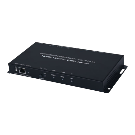
6. OPERATION CONTROLS AND FUNCTIONS 6.1 Front Panel USB-C HDMI SERV. CONTROL POWER SELECT SERV. Port: This port is reserved for firmware update use only. CONTROL Port: Connect directly, or through a network switch, to your PC/laptop to control the unit via Telnet/WebGUI. POWER LED: This LED will illuminate to indicate the unit is on and receiving power. - Page 10 DP IN Port: Connect to DisplayPort source equipment such as a PC or laptop. CAT.5e/6/7 OUT Port: Connect to a compatible HDBaseT Receiver with a single Cat.5e/6/7 cable for transmission of all data signals. PoH will also be supplied to a connected compatible PD Receiver. IR EXTENDER Port: Connect to an IR Extender to receive IR control signals and extend them to devices connected to the other end of the HDBaseT connection.
-
Page 11: Ir Cable Pinouts
6.3 IR Cable Pinouts IR Blaster IR Extender Cable Cable Power Infrared Infrared Power Not Used Ground 6.4 RS-232 Pinout and Defaults Serial Port Default Settings Baud Rate 19200 Data Bits Parity Bits None Stop Bits Flow Control None Console Bypass 3-pin Terminal Block 3-pin Terminal Block... -
Page 12: Webgui Control
6.5 WebGUI Control • Device Discovery Please obtain the “Device Discovery” software from your authorized dealer and save it in a directory where you can easily find it. Connect the unit and your PC/Laptop to the same active network and execute the “Device Discovery”... - Page 13 • WebGUI Overview After connecting to the WebGUI’s address in a web browser, the login screen will appear. Please enter the appropriate user name and password then click “Submit” to log in. Note: The default user name and password is “admin”. On the left side of the browser you will see the following menu tabs where all primary functions of the unit are controllable via the built in WebGUI.
-
Page 14: Switch Tab
6.5.1 Switch Tab This tab provides A/V routing control, HDCP management, auto switch control, A/V mask, and I/O renaming options. To assign a new A/V route, please click the Output button on the left and then click on the button of the preferred input port on the right. As each button is selected they will become highlighted. - Page 15 4) Output Edit: Provides control over the name of the output. ■ Set Output Name: To rename the output, type the new name in the space provided in the Edit window. The name can be up to 8 characters long. Click the “Save Change” button to confirm the change.
-
Page 16: Automation Tab
■ HDCP: The HDCP mode of each input can be set to “Follow Source”, “Follow Display”, or “Disabled”. Changes made to this setting occur immediately. Note: The VGA input cannot support HDCP. 6.5.2 Automation Tab The Automation tab provides control over the unit’s automatic control command broadcast behavior when any of the specified Automation Events occur. -
Page 17: Edid Tab
■ Wait: Set the length of time, in seconds, to wait after this Automation Event has been activated before ANY new Automation Event can be detected. ■ CEC Command: Shows the CEC command, in ASCII hex pairs, that will be sent when the specified Automation Event is activated. Click the “Edit”... - Page 18 ■ Download: To save an existing User EDID to your local PC, select the User EDID slot from the dropdown list and then press the “Download” button. Depending on your browser settings you will either be asked where to save the downloaded file, or the file will be transferred to the default download location on your PC.
- Page 19 This unit provides the following 6 default EDIDs: EDID NAME EDID CONTENT 1080P@60/PCM/2CH 1920×1080p@60Hz (148MHz), 8-bit color, LPCM 2.0 1080P@60/PCM/Bitstream/ MCH 1920×1080p@60Hz (148MHz), 8-bit color, LPCM 7.1 & Bitstream 4K@30/PCM/2CH 3840×2160p@30Hz (297MHz), Deep Color (8/10/12-bit), LPCM 2.0 4K@30/PCM/Bitstream/MCH 3840×2160p@30Hz (297MHz), Deep Color (8/10/12-bit), LPCM 7.1 &...
-
Page 20: Network Tab
6.5.4 Network Tab This tab provides network configuration options including changing the IP mode, viewing/setting the IP configuration, changing the admin login password, and changing the Web Login timeout. 1) IP Configuration: IP Mode may be switched between Static IP or DHCP. -
Page 21: System Tab
6.5.5 System Tab This tab provides serial number information, system configuration backup/ restore/reset, system reboot, and firmware update functions. 1) System Configuration ■ Download: The current system configuration, including routing and settings, may be saved as an XML file to a PC. Click the “Download” button to save the current system configuration to your local PC. -
Page 22: Telnet Control
6.6 Telnet Control Before attempting to use Telnet control, please ensure that both the unit and the PC are connected to the same active networks. To Access the Command Line Interface (CLI) Windows 7 Click Start, type “cmd” in the search field, and press Enter. -
Page 23: Rs-232 And Telnet Commands
6.7 RS-232 and Telnet Commands COMMAND DESCRIPTION AND PARAMETERS Show the full command list. help Show the full command list. set factory default Reset the unit to the factory defaults. set system reboot Reboot the unit. get fw ver Show the unit's current firmware version. set in N1 name N2 Set the name of the specified input. - Page 24 COMMAND DESCRIPTION AND PARAMETERS set in N1 hdcp mode N2 Set the HDCP behavior of the specified input. N1 = 1~4 [Input port] Available values for N2: [Disabled] [Follow source] [Follow display] get in N1 hdcp mode Show the current HDCP behavior used by the specified input.
- Page 25 COMMAND DESCRIPTION AND PARAMETERS set all in edid N1 Set the EDID to use when the “All” EDID mode is active. Available values for N1: [1080P, 2CH] [1080P, MCH] [4K@30, 2CH] [4K@30, MCH] [4K@60, 2CH] [4K@60, MCH] [User EDID 1] [User EDID 2] [User EDID 3] [User EDID 4]...
- Page 26 COMMAND DESCRIPTION AND PARAMETERS set in N1 edid N2 Set the EDID to use on the specified input. N1 = 1~4 [Input port] Available values for N2: [1080P, 2CH] [1080P, MCH] [4K@30, 2CH] [4K@30, MCH] [4K@60, 2CH] [4K@60, MCH] [User EDID 1] [User EDID 2] [User EDID 3] [User EDID 4]...
- Page 27 COMMAND DESCRIPTION AND PARAMETERS get edid N1 name Show the current name of the specified EDID. Available values for N1: [User EDID 1] [User EDID 2] [User EDID 3] [User EDID 4] set user N1 edid data N2 Upload a new EDID (in HEX format) for use as the specified User EDID.
- Page 28 COMMAND DESCRIPTION AND PARAMETERS set ipaddr N1 Set the unit's static IP address. N1 = X.X.X.X [X = 0 ~ 255] get ipaddr Show the unit's current IP address. set netmask N1 Set the unit's static netmask. N1 = X.X.X.X [X = 0 ~ 255] get netmask Show the unit's current netmask.
- Page 29 COMMAND DESCRIPTION AND PARAMETERS set automation event N1 Enable or disable the specified Automation cec A N2 Event's CEC response. Available values for N1: [Power on] [Out A source active] [Out A source lost] Available values for N2: [Event enabled] [Event disabled] get automation event N1 Show the current state of the specified...
- Page 30 COMMAND DESCRIPTION AND PARAMETERS get automation event N1 Show the delay time for the specified cec A delay Automation Event's CEC response. Available values for N1: [Power on] [Out A source active] [Out A source lost] set automation event N1 Set the length of time to wait after an cec A wait N2 Automation Event's CEC response has been...
- Page 31 COMMAND DESCRIPTION AND PARAMETERS set automation event N1 Set the CEC command to send when the cec A command N2 specified Automation Event is activated. Available values for N1: [Power on] [Out A source active] [Out A source lost] N2 = {CEC data} [Comma delimited hex pairs] get automation event N1...
-
Page 32: Connection Diagram
7. CONNECTION DIAGRAM Media Player 1.5m 60° HDMI Input Laptop 60° IR Input & Serial Equipped Output Laptop USB-C Input DisplayPort Input Tower PC RS-232 Stereo Input Network VGA Input Switch Power Supply CONSOLE EXTENDER BLASTER BYPASS TX RX G AUDIO USB-C HDMI... -
Page 33: Specifications
8. SPECIFICATIONS 8.1 Technical Specifications HDMI/DisplayPort/USB-C 18Gbps Bandwidth VGA Bandwidth 153MHz HDBaseT Bandwidth 10.2Gbps Input Ports 1×HDMI (Type-A) 1×DisplayPort 1×USB (Type-C) 1×VGA (HD-15) 1×Stereo Audio (3.5mm) Output Port 1×HDBaseT (RJ-45) Pass-through Ports 1×IR Extender (3.5mm) 1×IR Blaster (3.5mm) 1×RS-232 (3-pin Terminal Block) Control Ports 1×RS-232 (3-pin Terminal Block) 1×Ethernet (RJ-45) -
Page 34: Video Specifications
Operating Temperature 0˚C – 40˚C/32˚F – 104˚F Storage Temperature -20˚C – 60˚C/-4˚F – 140˚F Relative Humidity 20 – 90% RH (Non-condensing) Power Consumption 8.2 Video Specifications Supported Resolutions (Hz) HDMI DP USBC HDBT 720×400p@70/85 640×480p@60/72/75/85 ... - Page 35 Supported Resolutions (Hz) HDMI DP USBC HDBT 1600×1200p@60 1680×1050p@60 1920×1080i@50/60 1920×1080p@24/25/30 1920×1080p@50/60 1920×1200p@60RB ...
-
Page 36: Audio Specifications
8.3 Audio Specifications 8.3.1 Digital Audio HDMI/DisplayPort/USB-C Input LPCM Max Channels 8 Channels Sampling Rate (kHz) 32, 44.1, 48, 88.2, 96, 176.4, 192 Bitstream Supported Formats Standard & High-Definition HDBaseT Output LPCM Max Channels 8 Channels Sampling Rate (kHz) 32, 44.1, 48, 88.2, 96, 176.4, 192 Bitstream Supported Formats Standard &... -
Page 37: Cable Specifications
8.4 Cable Specifications 1080p 4K30 4K60 (4:4:4) (4:4:4) Cable Length 8-bit 12-bit 8-bit 8-bit High Speed HDMI Cable HDMI Input DisplayPort Cable DisplayPort Input USB-C Cable USB-C Input VGA Cable VGA Input Ethernet Cable Cat.5e/6 Cat.6a/7 Bandwidth Category Examples: •... -
Page 38: Hdbaset Features
8.5 HDBaseT Features HDBaseT Feature Set Transmitter Video & Audio Supported LAN Extension Unsupported Send power to Receiver Supported (PoH) Accept power from Receiver Unsupported IR Extension Supported RS-232 Extension Supported USB 2.0 Extension Unsupported... -
Page 39: Acronyms
9. ACRONYMS ACRONYM COMPLETE TERM Analog-to-Digital Converter ASCII American Standard Code for Information Interchange Audio/Video Audio/Video Receiver or Recorder Cat.5e Enhanced Category 5 cable Cat.6 Category 6 cable Cat.6a Augmented Category 6 cable Cat.7 Category 7 cable Consumer Electronics Control Command-Line Interface DHCP Dynamic Host Configuration Protocol... - Page 40 ACRONYM COMPLETE TERM Powered Device Power over HDBaseT Power Sourcing Equipment Signal-to-Noise Ratio Transmission Control Protocol Ultra-High-Definition Ultra-High-Definition Plus Universal Serial Bus Video Graphics Array WUXGA (RB) Widescreen Ultra Extended Graphics Array (Reduced Blanking) Extended Graphics Array...
- Page 44 CYPRESS TECHNOLOGY CO., LTD. www.cypress.com.tw...
Need help?
Do you have a question about the CH-1539TXPLPD and is the answer not in the manual?
Questions and answers