
Subscribe to Our Youtube Channel
Related Manuals for CYP CH-2537TXM-TB


Summary of Contents for CYP CH-2537TXM-TB
- Page 1 CH-2537TXM-TB 3×1 HDMI/VGA over HDBaseT Table Box with PoH (PD) Operation Manual Operation Manual...
- Page 2 ® registered trademarks of HDMI licensing Administrator, Inc.
- Page 3 DISCLAIMERS The information in this manual has been carefully checked and is believed to be accurate. Cypress Technology assumes no responsibility for any infringements of patents or other rights of third parties which may result from its use. Cypress Technology assumes no responsibility for any inaccuracies that may be contained in this document.
- Page 4 SAFETY PRECAUTIONS Please read all instructions before attempting to unpack, install or operate this equipment and before connecting the power supply. Please keep the following in mind as you unpack and install this equipment: • Always follow basic safety precautions to reduce the risk of fire, electrical shock and injury to persons.
-
Page 5: Table Of Contents
CONTENTS 1. Introduction ............1 2. Applications ............. 1 3. Package Contents ........... 1 4. System Requirements ........2 5. Features............2 6. Operation Controls and Functions ....3 6.1 Front Panel ..........3 6.2 Rear Panel........... 4 6.3 WebGUI Control .......... 5 6.3.1 Switch Tab .......... -
Page 6: Introduction
1. INTRODUCTION This UHD 3×1 HDMI/VGA over HDBaseT Table Box is an HDMI/VGA switch with audio embedding and HDBaseT output. The table box is designed to be placed on a table, or mounted to any typical table edge using a clamp. This transmitter can send uncompressed high-definition video/audio over a single cable up to a distance of 100 meters at 1080p@60Hz. -
Page 7: System Requirements
4. SYSTEM REQUIREMENTS • HDMI or VGA source equipment such as media players, video game consoles, PCs, or set-top boxes. • A compatible HDBaseT receiver capable of suppling PoH is required. • The use of Premium High Speed HDMI cables, and industry standard Cat.6, Cat.6A or Cat.7, is highly recommended. -
Page 8: Operation Controls And Functions
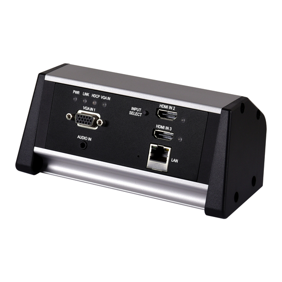
6. OPERATION CONTROLS AND FUNCTIONS 6.1 Front Panel HDMI IN 2 PWR LINK HDCP VGA IN INPUT SELECT VGA IN 1 HDMI IN 3 AUDIO IN PWR LED: This LED will illuminate to indicate the unit is on and receiving power. -
Page 9: Rear Panel
AUDIO IN Port: Connect to the stereo analog output of a device such as a CD player or PC for embedding into the HDBaseT output. RESET Pinhole: Press and hold for 5 seconds to reset the unit to its factory defaults. LAN Port: Connect to an Ethernet supporting device or to your local network, as appropriate, to extend the network to both ends of the HDBaseT connection and to control the unit. -
Page 10: Webgui Control
6.3 WebGUI Control • Device Discovery Please obtain the “Device Discovery” software from your authorized dealer and save it in a directory where you can easily find it. Connect the unit and your PC/Laptop to the same active network and execute the “Device Discovery”... - Page 11 • WebGUI Overview After connecting to the WebGUI’s address in a web browser, the login screen will appear. Please enter the appropriate user name and password then click “Submit” to log in. Note: The default user name and password is “admin”. On the left side of the browser you will see the following menu tabs where all primary functions of the unit are controllable via the built in WebGUI.
-
Page 12: Switch Tab
6.3.1 Switch Tab This tab provides video/audio routing control as well as control over HDCP behavior, freerun settings, and naming of the inputs and output. To assign a new video route, please click the output button and then click on the button of the preferred input port to route. - Page 13 ■ Audio Route: Control the audio used when the HDMI input is active. Selecting “Bypass” will use the HDMI signal’s normal audio. Selecting “External” will use the analog stereo audio. ■ Freerun Mode: Enable or disable the video freerun function. When this is enabled, the selected freerun color will be displayed on the screen if there is no live source on the selected input.
-
Page 14: Automation Tab
6.3.2 Automation Tab This tab provides control over the unit’s automatic control command broadcast behavior when the specified system Automation Events occur. Automation commands may be sent to 3rd party devices via standard CEC, or customizable RS-232. Note: Sending RS-232 commands requires the use of a compatible HDBaseT receiver with an RS-232 port. - Page 15 ■ Wait: Set the length of time, in seconds, to wait after this CEC Automation Event has been activated before ANY other Automation Event can be detected. ■ CEC Command: Set the CEC command to send when the specified Automation Event is activated. Clicking the “Test” button will send the command immediately.
-
Page 16: Edid Settings Tab
6.3.3 EDID Settings Tab This tab provides control over the EDID behavior of the unit. There are six internal EDIDs, three customer uploaded EDIDs, and one sink sourced EDID that can be assigned to each input port individually. The sink EDID and Customer EDIDs are also available for download to the connected PC. - Page 17 ■ Appoint: Selecting this allows for a different EDID to be assigned to each input. 4) Set EDID Input Content: This section provides a way to set the EDID to use with the selected input. ■ IN 1/IN 2/IN 3/All Input: Click the appropriate buttons to select the preferred input(s) and open the EDID Source table for assigning an EDID.
-
Page 18: System Settings Tab
6.3.4 System Settings Tab This tab provides access to control a number of system configuration controls including displaying the unit’s serial number, modifying web access privileges, changing the IP configuration, performing a factory reset, rebooting the system, and updating the firmware. 1) Serial Number: Displays the unit’s serial number. -
Page 19: Serial Control (Via Receiver)
6.4 Serial Control (Via Receiver) Serial Port Default Settings Baud Rate 19200 Data Bits Parity Bits None Stop Bits Flow Control None Note: RS-232 support requires the use of a compatible HDBaseT receiver with an RS-232 bypass port. 6.5 Telnet Control Before attempting to use Telnet control, please ensure that both the unit and the PC are connected to the same active networks. -
Page 20: Serial And Telnet Commands
6.6 Serial and Telnet Commands COMMAND Description and Parameters HELP Show all available commands. ? Show all available commands. GET FW VER Show the unit’s firmware version. GET MODEL NAME Show the unit’s model name. GET MODEL TYPE Show the unit’s product type. SET FACTORY DEFAULT... - Page 21 COMMAND Description and Parameters GET IPCONFIG Show the current IP address details. SET IPADDR N1 Set the static IP Address. N1 = X.X.X.X [X = 0~255, IP address] GET IPADDR Show the current IP address. SET NETMASK N1 Set the netmask address. N1 = X.X.X.X [X = 0~255, netmask] GET NETMASK...
- Page 22 COMMAND Description and Parameters SET OUT A NAME N1 Set the name of the output. N1 = {Name} [16 characters max] GET OUT A NAME Show the output’s current name. SET OUT A ROUTE N1 Switch the output routing source to the specified input. N1 = 1~3 [Input number] GET OUT A ROUTE...
- Page 23 COMMAND Description and Parameters SET OUT AUTO MODE N1 Enable or disable automatic source switching. Available values for N1: [Auto switch disabled] [Auto switch enabled] GET OUT AUTO MODE Show the current auto switch mode state. GET IN PORT NUMBER Show the number of inputs on the unit.
- Page 24 COMMAND Description and Parameters SET ALL IN EDID N1 Set the EDID to use when set to “All mode”. Available values for N1: [8-bit/1080p/2CH LPCM] [8-bit/1080p/MCH] [12-bit/4K@30/2CH LPCM] [12-bit/4K@30/MCH] [12-bit/4K@60/2CH LPCM] [12-bit/4K@60/MCH] [User 1] [User 2] [User 3] [Sink A] GET ALL IN EDID...
- Page 25 COMMAND Description and Parameters GET IN EDID LIST List all available EDID sources. SET EDID N1 NAME N2 Set the name of the specified User EDID. N1 = 7~9 [EDID number] N2 = {Name} [16 characters max] Note: Only User EDIDs can be renamed. GET EDID N1 NAME...
- Page 26 COMMAND Description and Parameters GET AUDIO OUT A ROUTE Show the current HDMI audio source. SET FREERUN A MODE N1 Enable or disable the freerun feature when there is no detected input. Available values for N1: [Freerun enabled] [Freerun disabled] GET FREERUN A MODE...
- Page 27 COMMAND Description and Parameters GET AUTOMATION EVENT N1 UART Show the current state of the specified Automation Event's RS-232 response. Available values for N1: [Power on] [Out A source active] [Out A source lost] SET AUTOMATION EVENT N1 UART DELAY N2 SEC Set the delay time that the specified Automation Event must continue to be true before sending the defined RS-232 command.
- Page 28 COMMAND Description and Parameters GET AUTOMATION EVENT N1 UART WAIT Show the wait time for the specified Automation Event's RS-232 re- sponse. Available values for N1: [Power on] [Out A source active] [Out A source lost] SET AUTOMATION EVENT N1 UART COMMAND N2 Set the RS-232 command string to send when the specified Automation Event is activated.
- Page 29 COMMAND Description and Parameters GET AUTOMATION EVENT N1 CEC Show the current state of the specified Automation Event's CEC re- sponse. Available values for N1: [Power on] [Out A source active] [Out A source lost] SET AUTOMATION EVENT N1 CEC DELAY N2 SEC Set the delay time that the specified Automation Event must continue to be true before sending the defined CEC command.
- Page 30 COMMAND Description and Parameters GET AUTOMATION EVENT N1 CEC WAIT Show the wait time for the specified Automation Event's CEC response. Available values for N1: [Power on] [Out A source active] [Out A source lost] SET AUTOMATION EVENT N1 CEC COMMAND N2 Set the CEC command to send when the specified Automation Event is activated.
- Page 31 COMMAND Description and Parameters GET UART 1 MODE Show the current RS-232 operation mode. SET UART 1 BAUDRATE N1 Set the RS-232 baud rate. Available values for N1: 4800 [4800 baud] 7200 [7200 baud] 9600 [9600 baud] 14400 [14400 baud] 19200 [19200 baud] 38400...
- Page 32 COMMAND Description and Parameters SET UART 1 PARITY N1 Set the parity value for RS-232. Available values for N1: [None] [Odd] [Even] GET UART 1 PARITY Show the current RS-232 parity setting. Note: Commands will not be executed unless followed by a carriage return. Commands are not case-sensitive.
-
Page 33: Connection Diagram
7. CONNECTION DIAGRAM Laptop or PC Game Console Laptop or PC Stereo HDMI HDMI Input Input Input Input HDMI IN 2 PWR LINK HDCP VGA IN INPUT SELECT VGA IN 1 HDMI IN 3 AUDIO IN Cat.5e/6/7 Cable Power Supply HDMI Output Network Switch... -
Page 34: Specifications
8. SPECIFICATIONS 8.1 Technical Specifications HDMI Bandwidth 18Gbps VGA Bandwidth 165MHz HDBaseT Bandwidth 10.2Gbps Input Ports 2×HDMI (Type-A) 1×VGA (HD-15) 1×Analog Stereo (3.5mm) Output Port 1×HDBaseT (RJ-45) Pass-through/Control Port 1×LAN (RJ-45) Service Port (Hidden) 1×USB 2.0 (Type A) Baud Rate 19200 Power Supply PoH (from Rx) -
Page 35: Video Specifications
8.2 Video Specifications Input Output Supported Resolutions (Hz) HDMI HDBaseT 720×400p@70/85 640×480p@60/72/75/85 720×480i@60 720×480p@60 720×576i@50 720×576p@50 800×600p@56/60/72/75/85 848×480p@60 ... -
Page 36: Audio Specifications
Input Output Supported Resolutions (Hz) HDMI HDBaseT 1920×1200p@60RB 2560×1440p@60RB 2560×1600p@60RB 2048×1080p@24/25/30 2048×1080p@50/60 3840×2160p@24/25/30 3840×2160p@50/60 (4:2:0) 3840×2160p@24, HDR10 ... -
Page 37: Analog Input
8.3.2 Analog Input Analog Input Max Audio Level 2Vrms Impedance 10kΩ Type Unbalanced 8.4 Cable Specifications 1080p 4K30 4K60 (4:4:4) (4:4:4) Cable Length 8-bit 12-bit 8-bit 8-bit High Speed HDMI Cable HDMI Input VGA Cable VGA Input Ethernet Cable Cat.5e/6 100m ... -
Page 38: Hdbaset Features
8.5 HDBaseT Features HDBaseT Feature Set Transmitter Video & Audio Extension Supported LAN Extension Supported Send power to Receiver Unsupported Accept power from Receiver Supported (PoH) IR Extension Unsupported RS-232 Extension Unsupported USB 2.0 Extension Unsupported 9. ACRONYMS ACRONYM COMPLETE TERM ASCII American Standard Code for Information Interchange Cat.5e... - Page 39 ACRONYM COMPLETE TERM HDTV High-Definition Television Internet Protocol Kilohertz Local Area Network Light-Emitting Diode LPCM Linear Pulse-Code Modulation Media Access Control Megahertz On-Screen Display Powered Device Power over HDBaseT Power Sourcing Equipment Transmission Control Protocol 4K UHD 4K Ultra-High-Definition (10.2Gbps max) 4K UHD 4K Ultra-High-Definition (18Gbps max) UHDTV...
- Page 40 CYPRESS TECHNOLOGY CO., LTD. www.cypress.com.tw...
Need help?
Do you have a question about the CH-2537TXM-TB and is the answer not in the manual?
Questions and answers