
Related Manuals for Bruker BioSpin GRASI-1.0


Summary of Contents for Bruker BioSpin GRASI-1.0
- Page 1 Bruker BioSpin GRASI 1.0 Gradient and Shim Interface Unit User Manual Version NMR Spectroscopy think forward...
- Page 2 The information in this manual may be altered without notice. BRUKER BIOSPIN accepts no responsibility for actions taken as a result of use of this manual. BRUKER BIOSPIN accepts no liability for any mistakes contained in the manual, leading to coincidental damage, whether during installation or operation of the instrument.
-
Page 3: Table Of Contents
Front panel buttons ................19 Rear panel connectors ..............19 Gradient Coil Code connector from Gradient set ......19 Status and Command connector from GPSCU ......20 Status and Command connector to amplifier ......... 21 User Manual Version 001 BRUKER BIOSPIN 3 (41) - Page 4 Settings Update ................30 Firmware Update ................. 31 Device Reset ................32 Sub Toolbar Diagnostics ..............33 Event Log ..................33 Specification ..............35 General specifications ..............35 Figures ................37 Tables ................39 4 (41) BRUKER BIOSPIN User Manual Version 001...
-
Page 5: Introduction
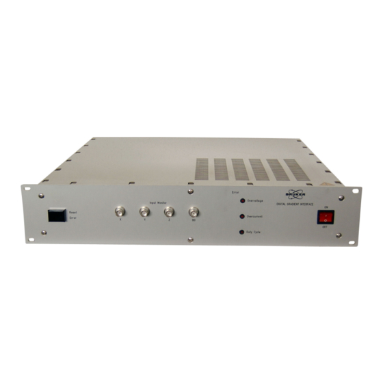
Gradient Amplifier Channel Y Gradient Amplifier Gradient Controller GRASI Unit & DPP Channel Z Gradient Amplifier Channel B0 Gradient Amplifier Figure 1.1. GRASI Unit diagram Figure 1.2. GRASI Gradient and Shim Unit User Manual Version 001 BRUKER BIOSPIN 5 (41) - Page 6 Introduction 6 (41) BRUKER BIOSPIN User Manual Version 001...
-
Page 7: Safety
Sprinkling or pouring liquids on the device is forbidden. Use a wet or alcohol soaked rag to clean the EMB. For corrective actions contact the BRUKER BIOSPIN representative in your coun- try. Labels Labels are provided to alert operating and service personnel to conditions that may cause personal injury or damage to the equipment from misuse or abuse. -
Page 8: Manufacturer's Nameplate
(F) Wires This field indicates number of wires with the ground in the mains cord. • (G) Part Number This field indicates the assembly number that identifies the part number of the product. 8 (41) BRUKER BIOSPIN User Manual Version 001... -
Page 9: Warning Signs
Labels Warning signs 2.2.3 Table 2.1. Danger DANGER! Please disconnect line cord before opening or prevent potential hazards such as: • Electric schock on power supply. • Contact burn with heatsink. User Manual Version 001 BRUKER BIOSPIN 9 (41) - Page 10 Safety 10 (41) BRUKER BIOSPIN User Manual Version 001...
-
Page 11: Installation
The installation of the device must be done only by an authorized and qualified technician, in total accordance with the running standards. Every breakdown due to a non-respect of the following instructions will not be attributable to Bruker and will not be covered by the guarantee clauses. -
Page 12: Environment Requirements
3. After approximatively one minute, the LEDs turn off. The GRASI unit is ready for use. 4. If the LEDs do not turn off, see the"Troubleshooting" on page 15. 12 (41) BRUKER BIOSPIN User Manual Version 001... -
Page 13: Operation
U FROM AMPLIFIER X U FROM AMPLIFIER Y ADC 1 U FROM AMPLIFIER Z POWER CONTROL I FROM AMPLIFIER X I FROM AMPLIFIER Y ADC 2 I FROM AMPLIFIER Z Figure 4.1. Functional block diagram User Manual Version 001 BRUKER BIOSPIN 13 (41) -
Page 14: Amplifier Selection
The first step before starting is to select the type of amplifier used with the GRASI unit. This selection is performed using a dedicated Web page. This action should be done only by Bruker trained personnel. Choosing a wrong amplifier type can lead to irreversible damage of the entire spectrometer. The selection is done once at the first switch on. -
Page 15: Error Messages
DSP control could not be started check if the Coil Code is selected The three LEDs are blinking in An internal error occurred HW-Reset the GRASI Unit turn User Manual Version 001 BRUKER BIOSPIN 15 (41) - Page 16 Operation 16 (41) BRUKER BIOSPIN User Manual Version 001...
-
Page 17: Technical Description
The GRASI Unit is powered by the mains input. Main characteristics • AC input voltage range : 208-230VAC • AC inrush current : 40A at 230VAC • Power consumption : 220VAC 300mA • Fuses : 2A T 250VAC User Manual Version 001 BRUKER BIOSPIN 17 (41) -
Page 18: Front Panel Connectors
BNC female of Monitor Y definition Pins Descriptions MONITOR_Y MONITOR_Y_GND Table 5.3. BNC female of Monitor Z definition Pins Descriptions MONITOR_Z MONITOR_Z_GND Table 5.4. BNC female of Monitor B0 definition Pins Descriptions MONITOR_B0 MONITOR_B0_GND 18 (41) BRUKER BIOSPIN User Manual Version 001... -
Page 19: Front Panel Indicators
This unit is equiped with a "RESET" button to reset errors. Figure 5.4. Error reset button Rear panel connectors Gradient Coil Code connector from Gradient set 5.6.1 Coil Code Interface Connector from Coil to GRASI. Figure 5.5. Sub-D 37 pin female connector User Manual Version 001 BRUKER BIOSPIN 19 (41) -
Page 20: Status And Command Connector From Gpscu
Unused Unused TC_2 Unused Unused TC_3 Unused Status and Command connector from GPSCU 5.6.2 Status and Command connectors from GPSCU to GRASI on each channel. Figure 5.6. Sub-D 15 pin male connector 20 (41) BRUKER BIOSPIN User Manual Version 001... -
Page 21: Status And Command Connector To Amplifier
Figure 5.7. Sub-D 15 pin female connector Table 5.7. Sub-D 15 pin female definition Pins Descriptions Pins Descriptions SHIELD (2, 9) RESET VOLT MON SHIELD (4, 11) CURR MON NORMAL SHIELD (13, 14) SHIELD (5, 6, 15) User Manual Version 001 BRUKER BIOSPIN 21 (41) -
Page 22: Interlock Binder Connector
INTERLOCK INTERLOCK_GND Coil Code Binder connector 5.6.5 Coil Code Binder from GRASI to GPSCU. Figure 5.9. Binder 6 pin female connector Table 5.9. Binder 6 pin female definition Pins Descriptions Pins Descriptions 22 (41) BRUKER BIOSPIN User Manual Version 001... -
Page 23: B0 Output Twinaxe Connector
The RJ45 connector for the Ethernet 10/100 Mbps link is mounted directly on the CPU-A Board. Figure 5.11. RJ45 8 pin connector Table 5.11. RJ45 8 pin definition Pins Descriptions Pins Descriptions Transmit + (Tx+) Transmit - (Tx-) Receive - (Rx-) Receive + (Rx+) User Manual Version 001 BRUKER BIOSPIN 23 (41) -
Page 24: Rear Panel Overview
Technical description Rear panel overview Figure 5.12. Rear panel view 24 (41) BRUKER BIOSPIN User Manual Version 001... -
Page 25: Servicing The Grasi
URL. Some of these pages are only status pages to inform the operator, some other pages allow to modify several parameters of the GRASI unit. You should get the following start screen. User Manual Version 001 BRUKER BIOSPIN 25 (41) -
Page 26: Sub Toolbar Information
6.2.1 This page shows the main information of the device. On the left frame, the operator can choose a submenu to get the remaining information concerning the device. Figure 6.1. Device Information 26 (41) BRUKER BIOSPIN User Manual Version 001... -
Page 27: Device Status
6.2.2 Select the tab "Information", then the item "Device status". This page shows the device status. When a fault is detected, the corresponding item is in red color. Figure 6.2. Device Status User Manual Version 001 BRUKER BIOSPIN 27 (41) -
Page 28: Bis Content
BIS Content 6.2.3 This page shows the BIS content of the different GRASI channels. It also shows the BIS content of the CPU board and the Controller board. Figure 6.3. BIS Content 28 (41) BRUKER BIOSPIN User Manual Version 001... -
Page 29: Sub Toolbar Basic Operations
Select the tab "Basic Operations". If necessary, click the item "Reset error" on the left menu. This has the same effect as the "Reset error" button on the GRASI front panel. Figure 6.4. Reset Error User Manual Version 001 BRUKER BIOSPIN 29 (41) -
Page 30: Sub Toolbar Maintenance
Sub Toolbar Maintenance Settings Update 6.4.1 When necessary, some settings may be updated or upgraded via BRUKER data files. In this case, select the tab "Maintenance", then the item "Settings update" in the left menu. Select the settings file with the browser, then click the "Update" button to start the update process. -
Page 31: Firmware Update
"Update" button to start the update process. This process may request several minutes. Please do not quit before the window changes and informs that the update was successful. The two windows are the following: Figure 6.6. Firmware Update User Manual Version 001 BRUKER BIOSPIN 31 (41) -
Page 32: Device Reset
In order to avoid an undesired reset, the operator will have to confirm by clicking the "Perform Software Reset" button. Resetting the device sets it into the same state as after the first turn on. Figure 6.7. Device Reset 32 (41) BRUKER BIOSPIN User Manual Version 001... -
Page 33: Sub Toolbar Diagnostics
Select the tab "Diagnostics", then the item "Event log" in the left menu. On this page, the operator can verify which actions have been performed and which events happened since the unit has been switched on. Figure 6.8. Event Log User Manual Version 001 BRUKER BIOSPIN 33 (41) - Page 34 Servicing the GRASI 34 (41) BRUKER BIOSPIN User Manual Version 001...
-
Page 35: Specification
Natural Convection Size 19" rack cabinet x 2U height x 460mm depth Weight Power requirements 100 - 240VAC ±10%, single phase 50-60Hz Bruker part number W1522072 Consumption max. 69VA (0,300A @ 230VAC) User Manual Version 001 BRUKER BIOSPIN 35 (41) -
Page 36: Table 7.2. Grasi Unit Inputs / Outputs Specifications
Interlock to GPSCU (on 2 pin BINDER Interlock Connector) A0 to A6 for Coil Code (on SUB-D 37 Coil Code Connector from Gradient Set and 6 pin BINDER Coil Code Connector to GPSCU) 36 (41) BRUKER BIOSPIN User Manual Version 001... -
Page 37: Figures
Figure 6.3. BIS Content ..................28 Figure 6.4. Reset Error ..................29 Figure 6.5. Settings Update ...................30 Figure 6.6. Firmware Update ..................31 Figure 6.7. Device Reset ..................32 Figure 6.8. Event Log ....................33 7 Specification User Manual Version 001 BRUKER BIOSPIN 37 (41) - Page 38 38 (41) BRUKER BIOSPIN User Manual Version 001...
-
Page 39: Tables
Table 5.10. Twinaxe definition ................23 Table 5.11. RJ45 8 pin definition ................23 6 Servicing the GRASI 7 Specification Table 7.1. GRASI Unit Specifications ..............35 Table 7.2. GRASI unit Inputs / Outputs specifications ...........36 User Manual Version 001 BRUKER BIOSPIN 39 (41) - Page 40 40 (41) BRUKER BIOSPIN User Manual Version 001...
- Page 41 End of Document User Manual Version 001 BRUKER BIOSPIN 41 (41)
- Page 42 Bruker BioSpin, your solution partner Bruker BioSpin provides a world class, market leading range of analysis solutions for your life and materials science needs. Bruker BioSpin Group info@bruker biospin.com www.bruker biospin.com...
Need help?
Do you have a question about the BioSpin GRASI-1.0 and is the answer not in the manual?
Questions and answers