
Related Manuals for Bruker minispec TC3


Summary of Contents for Bruker minispec TC3
- Page 1 minispec ● Temperature Unit TC3 User Manual Version 003 Innovation with Integrity...
- Page 2 Bruker BioSpin AIC © October 26, 2015 Bruker Corporation P/N: H148851 For further technical assistance for this product, please do not hesitate to contact your nearest BRUKER dealer or contact us directly at: Bruker Corporation Am Silberstreifen 76287 Rheinstetten Germany Phone: + 49 721 5161 0 E-mail: minispec.SLS@bruker.com...
-
Page 3: Table Of Contents
Contents Contents About This Manual .......................... 5 Policy Statement ......................... 5 Symbols and Conventions .................... 5 Introduction............................ 7 Overview .......................... 7 Features.......................... 8 Intended Use........................ 8 Safety.............................. 9 Safety Notices........................ 9 3.1.1 Power Cord Set Requirements ................... 9 3.1.2 Power Cord Safety Maintenance .................. 9 3.1.3 Mains Disconnect........................ 9 3.1.4 Mechanical Hazards ...................... 10 3.1.5 Thermal Hazards ...................... 11 3.1.6... - Page 4 Contents Cleaning Instructions ...................... 31 Dismantling and Disposal........................ 33 Safety.......................... 33 Dismantling ........................ 33 Disposal .......................... 34 10 Contact .............................. 35 List of Figures........................... 37 List of Tables ............................ 39 Index .............................. 41 H148851_3_003...
-
Page 5: About This Manual
Options and accessories may or may not be illustrated in each figure. Policy Statement It is the policy of Bruker to improve products as new techniques and components become available. Bruker reserves the right to change specifications at any time. - Page 6 About This Manual CAUTION CAUTION indicates a hazardous situation, which, if not avoided, may result in minor or moderate injury or severe material or property damage. This is the consequence of not following the warning. 1. This is the safety condition. u This is the safety instruction.
-
Page 7: Introduction
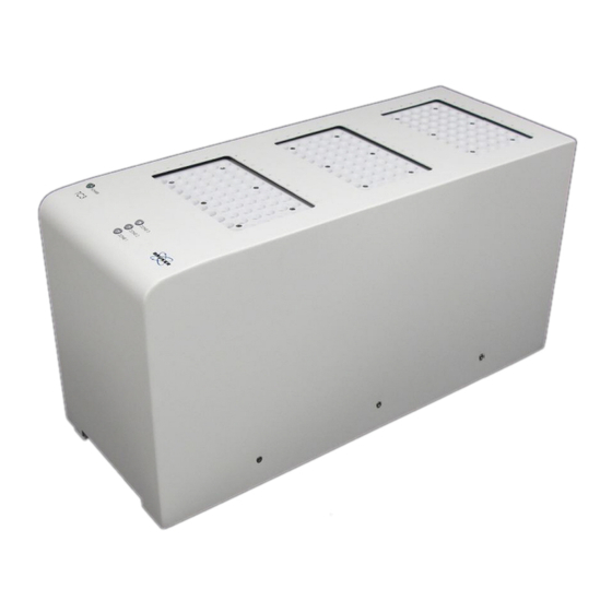
Introduction Introduction Overview The TC3 temperature unit, also called a dry bath, allows you to control the temperature of samples in an ASX-7000-series sample changer. It heats or chills the samples under the control of a host computer. Figure 2.1: The TC3 Unit. The temperature unit comes in three versions: •... -
Page 8: Features
Introduction Features Temperature Range Three zones hold samples at 0° C to +100° C. Sample Changer Compatibility Use only with an ASX-7600 pick-and-place NMR sample changer. Chemical Compatibility Exposed surfaces are made of corrosion‑resistant stainless steel alloys or anodized aluminum. Intended Use This equipment is designed for use in analytical laboratories performing chemical analysis of samples. -
Page 9: Safety
Any obvious damage to the case (from a drop or fall) should be checked by service personnel for loose or damaged parts. Refer to the individual part lists, or contact Bruker, for approved replacement parts. 3.1.3 Mains Disconnect The power switch on the rear panel is not the mains disconnect. -
Page 10: Mechanical Hazards
Safety WARNING Fire and Shock Hazard Incorrect installation or use of the power supply may result in a fire or shock hazard. u Use only the provided power supply. u The power supply must be plugged into an outlet which has a protective ground connection. -
Page 11: Thermal Hazards
Safety 3.1.5 Thermal Hazards WARNING Burn Hazard Incorrect handling of vials or inserting fingers into any holes in the device may result in burn injuries. u Do not handle vials from heated zones until they have been given time to cool. u Do not attempt to insert fingers into any holes in the device. -
Page 12: Explanation Of Caution And Warning Notices
Safety WARNING Chemical Hazards Incorrect use of chemicals used in and near the device may result in injury or property damage. u Learn about the chemicals which will be used in and near the device, and observe the necessary precautions. u Always use appropriate personal protective equipment, including protective eyewear. -
Page 13: Electromagnetic Interference
Safety Lifting Hazard – Single person lift could cause injury. • Use assistance when moving or lifting. Table 3.1: Explanation of Caution and Warning Notices Electromagnetic Interference FEDERAL COMMUNICATIONS COMMISSION (FCC) NOTICE This equipment has been tested and found to comply with the limits for a Class A digital device, pursuant to Part 15 of the FCC Rules. -
Page 14: Explanation Of Regulatory Marks
Safety Explanation of Regulatory Marks The CE mark is a registered trademark of the European Community. This CE mark shows that the product complies with all the relevant European Legal Directives. H148851_3_003... -
Page 15: Technical Data
Technical Data Technical Data Environmental Characteristics These environmental characteristics indicate the conditions for safe operation. Instrument performance may depend on the ambient conditions. Operating Temperature +5° C to +40° C (+41° F to +104° F) Non-Operating +0° C to +55° C (+32° to +131° F) Temperature Operating Altitude Up to 2,000 m (6,562 ft.) -
Page 16: Gas Connection
Technical Data Gas Connection One fitting is provided for nitrogen purge gas. The nitrogen source must be regulated to a pressure of no more than 35 kPa (5 psi, 0.35 bar). A typical gas flow of 0.5 liter/minute shall apply. Thermal Characteristics Figure 4.1: Thermal Characteristics of a 3-Zone 10 mm SFC Version Zone... -
Page 17: Figure 4.2: Thermal Characteristics Of A 1-Zone 10 Mm Polymers Version
Technical Data Figure 4.2: Thermal Characteristics of a 1-Zone 10 mm Polymers Version Zone Default Range Ambient +5° C to +110° C Figure 4.3: Thermal Characteristics of a 2-Zone 26 mm Version Zone Temperature Range Ambient +5° C to +80° C Ambient + 5° C to +80° C H148851_3_003... - Page 18 Technical Data H148851_3_003...
-
Page 19: Transport, Packaging And Storage
Transport, Packaging and Storage Transport, Packaging and Storage WARNING Lifting Hazard Lifting without assistance may cause injury. u Two people are required to lift the device. u Lifting should be done with a person situated on either side of the device. Inspect external packaging upon receipt for signs of shipping damage. - Page 20 Transport, Packaging and Storage H148851_3_003...
-
Page 21: Installation
Installation Installation Site Selection Follow the guidelines in the sample changer Operator's Manual to choose a location for the system. Keep in mind that: • You will need to be able to access the back of the system to install cables and tubing. •... -
Page 22: Figure 6.1: Base Of The Sample Changer
Installation The temperature unit is positioned by means of two spring-loaded pins: Figure 6.1: Base of the Sample Changer Figure 6.2: Bottom of the Temperature Unit • If using a version which is equipped with an air filter, remove the filter drawer from the front of the temperature unit. -
Page 23: Connecting The Cables To The Sample Changer
Installation Note: You can mount the temperature unit on a bench top or table using the optional table adapter: Figure 6.3: Optional Table Adapter Connecting the Cables to the Sample Changer • Connect the 9-pin serial cable to the COM 2 port on the sample changer. Figure 6.4: Serial Cable Connected to the Back of the Sample Changer. -
Page 24: Connecting To A Power Source
Installation Figure 6.5: Serial Connector on the Unit. • Connect the sample changer to the host computer as described in the sample changer Operator's Manual. • If using a TC3 and TC6 temperature unit together, connect the supplied RS-485 serial cable between the two temperature units. Connecting to a Power Source •... -
Page 25: Connecting The Nitrogen Supply
Installation Figure 6.6: Power Connections for the Unit • Plug the power cord into a power outlet. It is important to use the appropriate power cord for your country. See Power Cord Set Requirements [} 9]. Connecting the Nitrogen Supply A source of low-pressure nitrogen may be connected for purging the unit. The nitrogen displaces air within the unit to prevent condensation. - Page 26 Installation H148851_3_003...
-
Page 27: Operation
Operation Operation Power-On To turn the system on, first turn the temperature unit switch ON, then the sample changer. Power-Off To turn the system off, first turn the sample changer power switch OFF, then the temperature unit. In case of emergency, or before performing maintenance, remove the power cord from the back of the temperature unit and from the sample changer. - Page 28 Operation H148851_3_003...
-
Page 29: Maintenance
Maintenance Maintenance Replacing the Fuse WARNING Fire and Shock Hazard Using an incorrect fuse may cause fire or personal injury. . u Replace the fuses only with a 10A 250V slow-blow 5x20 mm fuse (T10AL250V). Two fuses are located in the power supply, just above the power cord connector. Figure 8.1: Fuse Holder for the TC3 •... -
Page 30: Replacing The Air Filter
• Plug the power cord back in. Replacing the Air Filter The 3-zone 10 mm SFC version of the TC3 includes a user-replaceable air filter. Contact Bruker for information on replacement filters. WARNING Laceration Hazard If the unit power is left on, the spinning fan blade just above the filter may cause injury. -
Page 31: Cleaning Instructions
Maintenance Figure 8.4: Removing and Installing the Filter • Install the new filter. • Close the filter drawer. • Turn the power back on. Cleaning Instructions To clean the exterior surfaces of the device, complete the following steps: • Shut down and unplug the device. •... - Page 32 Maintenance H148851_3_003...
-
Page 33: Dismantling And Disposal
Installation, initial commissioning, retrofitting, repairs, adjustments or dismantling of the device must only be carried out by Bruker Service or personnel authorized by Bruker. Damage due to servicing that is not authorized by Bruker is not covered by your warranty. Safety... -
Page 34: Disposal
Dismantling and Disposal Disposal After the lifespan of the product, Bruker takes responsibility for disassembly and disposal in accordance with the European Directive WEEE 2012/19/EC. Bruker BioSpin will take back the components free of charge upon request by the customer. If the customer wants to arrange disposal on their own, then this must be stated when the product is ordered. -
Page 35: 10 Contact
WEEE DE43181702 Bruker BioSpin Hotlines Contact our Bruker BioSpin service centers. Bruker BioSpin provides dedicated hotlines and service centers, so that our specialists can respond as quickly as possible to all your service requests, applications questions, software or technical needs. - Page 36 Contact H148851_3_003...
-
Page 37: List Of Figures
List of Figures List of Figures Figure 2.1: The TC3 Unit........................ Figure 3.1: Bottom View with Filter Drawer Removed ..............Figure 4.1: Thermal Characteristics of a 3-Zone 10 mm SFC Version ........... Figure 4.2: Thermal Characteristics of a 1-Zone 10 mm Polymers Version ........Figure 4.3: Thermal Characteristics of a 2-Zone 26 mm Version ........... - Page 38 List of Figures H148851_3_003...
-
Page 39: List Of Tables
List of Tables List of Tables Table 3.1: Explanation of Caution and Warning Notices ..............Table 4.1: Environmental Characteristics ................... Table 4.2: Electrical Characteristics....................H148851_3_003... - Page 40 List of Tables H148851_3_003...
-
Page 41: Index
Index Index pollution degree .......... 15 power cord............ 9 Regulatory notices.......... 9 Air filter ............. 30 avis Canadien........... 13 Safety information .......... 9 cleaning ............ 31 condensation humidity ............ 19 Table adapter ........... 23 Temperature Operating............. 15 Disassembly ............. 34 Temperature range........... 16 disposal ............ 34 Tubing kinks ............ 19 Electrical characteristics ........ 15 Voltage selection .......... 24 FCC notice ............ 13 Filter.............. 30 WEEE notice ............ 34... - Page 42 Index H148851_3_003...
- Page 43 H148851_3_003...
- Page 44 ● Bruker Corporation info@bruker.com www.bruker.com Order No: H148851...
Need help?
Do you have a question about the minispec TC3 and is the answer not in the manual?
Questions and answers