Sign In
Upload
Manuals
Brands
Bruker Manuals
Laboratory Equipment
BioSpin GRASI-1.0
Bruker BioSpin GRASI-1.0 Shim Interface Manuals
Manuals and User Guides for Bruker BioSpin GRASI-1.0 Shim Interface. We have
1
Bruker BioSpin GRASI-1.0 Shim Interface manual available for free PDF download: User Manual
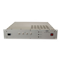
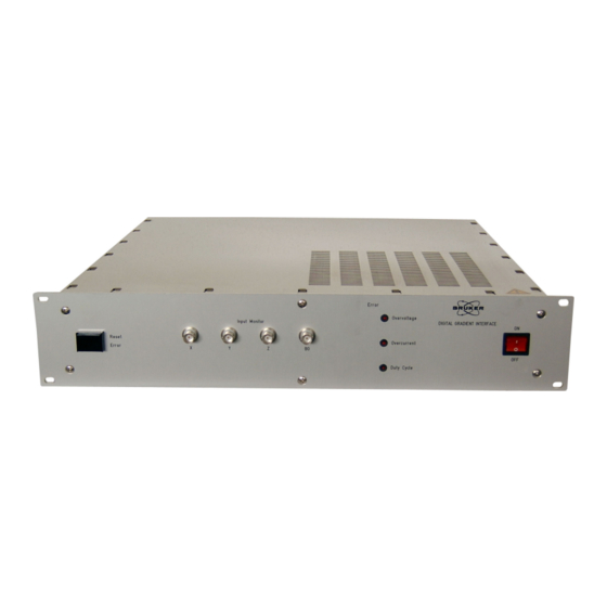
Bruker BioSpin GRASI-1.0 User Manual (42 pages)
Gradient and Shim Interface Unit
Brand:
Bruker
| Category:
Laboratory Equipment
| Size: 2 MB
Table of Contents
Table of Contents
3
Contents
3
Table of Contents
3
1 Introduction
5
Figure 1.1. GRASI Unit Diagram
5
Figure 1.2. GRASI Gradient and Shim Unit
5
2 Safety
7
Instructions
7
Labels
7
Figure 2.1. Identifying Plate
7
Identifying Plate
7
Figure 2.2. Manufacturer's Nameplate
8
Manufacturer's Nameplate
8
Table 2.1. Danger
9
Warning Signs
9
3 Installation
11
Initial Inspection
11
Claim for Damage
11
Mechanical Check
11
Reshipment and Repackaging Requirements
11
Environment Requirements
12
Installation Requirements
12
Bench Operation
12
System Check
12
Initial Turn on Procedure
12
4 Operation
13
General Fonctions
13
Figure 4.1. Functional Block Diagram
13
Amplifier Selection
14
Calibration
14
Coil Code Selection
14
Initialisation Process
14
Powering up
14
Error Messages
15
5 Technical Description
17
General Description
17
Power Requirements
17
Figure 5.1. Housing Dimensions
17
Main Characteristics
17
Front Panel Connectors
18
Figure 5.2. Figure 7 : BNC Female Connector
18
Table 5.1. BNC Female of Monitor X Definition
18
Table 5.2. BNC Female of Monitor y Definition
18
Table 5.3. BNC Female of Monitor Z Definition
18
Table 5.4. BNC Female of Monitor B0 Definition
18
Technical Description
18
Front Panel Indicators
19
Front Panel Buttons
19
Rear Panel Connectors
19
Figure 5.3. Red Led Indicator
19
Figure 5.4. Error Reset Button
19
Figure 5.5. Sub-D 37 Pin Female Connector
19
Gradient Coil Code Connector from Gradient Set
19
Figure 5.6. Sub-D 15 Pin Male Connector
20
Status and Command Connector from GPSCU
20
Table 5.5. Sub-D 37 Pin Female Definition
20
Figure 5.7. Sub-D 15 Pin Female Connector
21
Status and Command Connector to Amplifier
21
Table 5.6. Sub-D 15 Pin Male Definition
21
Table 5.7. Sub-D 15 Pin Female Definition
21
Coil Code Binder Connector
22
Figure 5.8. Binder 2 Pin Female Connector
22
Figure 5.9. Binder 6 Pin Female Connector
22
Interlock Binder Connector
22
Table 5.8. Binder 2 Pin Female Definition
22
Table 5.9. Binder 6 Pin Female Definition
22
B0 Output Twinaxe Connector
23
Figure 5.10.Twinaxe Connector
23
Figure 5.11.RJ45 8 Pin Connector
23
Interface Connector Ethernet 10/100
23
Table 5.10. Twinaxe Definition
23
Table 5.11. RJ45 8 Pin Definition
23
Rear Panel Overview
24
Figure 5.12.Rear Panel View
24
6 Servicing the GRASI
25
Accessing the GRASI Unit
25
Sub Toolbar Information
26
Device Information
26
Figure 6.1. Device Information
26
Device Status
27
Figure 6.2. Device Status
27
BIS Content
28
Figure 6.3. bis Content
28
Sub Toolbar Basic Operations
29
Figure 6.4. Reset Error
29
Reset Error
29
Sub Toolbar Maintenance
30
Figure 6.5. Settings Update
30
Settings Update
30
Figure 6.6. Firmware Update
31
Firmware Update
31
Device Reset
32
Figure 6.7. Device Reset
32
Sub Toolbar Diagnostics
33
Event Log
33
Figure 6.8. Event Log
33
7 Specification
35
General Specifications
35
Table 7.1. GRASI Unit Specifications
35
Table 7.2. GRASI Unit Inputs / Outputs Specifications
36
Figures
37
Tables
39
Advertisement
Advertisement
Related Products
Bruker BioSpin NMR CASE
Bruker BioSpin 500'154 USP
Bruker BioSpin NMR Fourier 300
Bruker Gilson
Bruker 300'154 Ascend DNP
Bruker 300'89 Ascend
Bruker 500'54 Ascend ULH
Bruker 500'89 Ascend Aeon
Bruker 600'54 Ascend ULH
Bruker 700'54 Ascend
Bruker Categories
Laboratory Equipment
Measuring Instruments
Industrial Equipment
Security Sensors
Accessories
More Bruker Manuals
Login
Sign In
OR
Sign in with Facebook
Sign in with Google
Upload manual
Upload from disk
Upload from URL