Sign In
Upload
Download
Table of Contents
Contents
Add to my manuals
Delete from my manuals
Share
URL of this page:
HTML Link:
Bookmark this page
Add
Manual will be automatically added to "My Manuals"
Print this page
×
Bookmark added
×
Added to my manuals
Manuals
Brands
Bruker Manuals
Laboratory Equipment
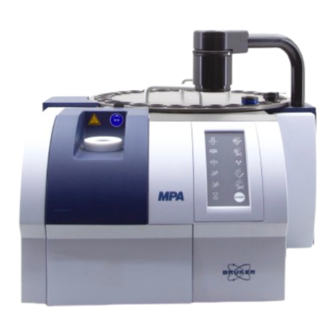
MPA I
Service documentation
Bruker MPA I Service Documentation
Replacement of the laser q101/a
Hide thumbs
1
2
Table Of Contents
3
4
5
6
7
8
9
10
11
12
13
14
15
16
17
18
19
20
21
22
23
24
25
26
page
of
26
Go
/
26
Contents
Table of Contents
Troubleshooting
Bookmarks
Table of Contents
Table of Contents
Replacement of the Laser (Q101/A)
Qualified Personnel
Safety
Electrical Shock
Tools
Matrix I: How to Remove the Housing Cover of the Laser
MPA I: How to Remove the Housing Cover of the Laser
MATRIX I and MPA I: How to Remove the Laser Module
MATRIX I and MPA I: How to Install the New Laser Module
Resetting the Laser Parameters/Calibrate the Laser Wavenumber
Troubleshooting
OPUS Status Light
OPUS Dialog Window
Service-Addresses
Advertisement
Quick Links
1
Table of Contents
2
Troubleshooting
Download this manual
MPA I/MATRIX I
Replacement of the Laser
Service documentation
Table of
Contents
Previous
Page
Next
Page
1
2
3
4
5
Advertisement
Table of Contents
Need help?
Do you have a question about the MPA I and is the answer not in the manual?
Ask a question
Questions and answers
Related Manuals for Bruker MPA I
Laboratory Equipment Bruker 500'54 Ascend ULH User Manual
(102 pages)
Laboratory Equipment Bruker minispec User Manual
Sample automation xyz sample changer (82 pages)
Laboratory Equipment Bruker NMR 600'89 Ascend DNP User Manual
(102 pages)
Laboratory Equipment Bruker NMR 300 54 Ascend ULH User Manual
(100 pages)
Laboratory Equipment Bruker NMR 400 89 Ascend DNP User Manual
(106 pages)
Laboratory Equipment Bruker NMR 600 89 Ascend DNP User Manual
(106 pages)
Laboratory Equipment Bruker DektakXT User Manual
Stylus profiler (83 pages)
Laboratory Equipment Bruker NMR iProbe HR-Liquids User Manual
(56 pages)
Laboratory Equipment Bruker TENSOR User Manual
(158 pages)
Laboratory Equipment Bruker QUANTAX EDS User Manual
Energy-dispersive x-ray spectrometer for electron microscopy (119 pages)
Laboratory Equipment Bruker D2 PHASER User Manual
(120 pages)
Laboratory Equipment Bruker SamplePro hr-MAS Service Manual
(268 pages)
Laboratory Equipment Bruker D8 Series User Manual
(96 pages)
Laboratory Equipment Bruker RS Service Manual
Nmr spectroscopy (157 pages)
Laboratory Equipment Bruker CryoProbe System Installation Manual
(93 pages)
Laboratory Equipment Bruker CryoProbe User Manual
(107 pages)
This manual is also suitable for:
Matrix i
Table of Contents
Print
Rename the bookmark
Delete bookmark?
Delete from my manuals?
Login
Sign In
OR
Sign in with Facebook
Sign in with Google
Upload manual
Upload from disk
Upload from URL


Need help?
Do you have a question about the MPA I and is the answer not in the manual?
Questions and answers