Firegear FPB-25SFBSMT-N Installation And Operating Instructions Manual
Outdoor square flat fire pit discs
Hide thumbs
Also See for FPB-25SFBSMT-N:
- Installation and operating instructions manual (38 pages) ,
- Installation and operating instructions manual (38 pages)
Table of Contents
Advertisement
Natural Gas
FPB-25SFBSMT-N
FPB-25SFBSTMSI-N
FPB-25SFBSTFS-N
FPB-30SFBSMT-N
FPB-30SFBSTMSI-N
FPB-34SFBSMT-N
FPB-34SFBSTMSI-N
Outdoor Square Flat Fire Pit Discs
Installation and Operating Instructions
IF YOU CANNOT READ OR UNDERSTAND THESE INSTALLATION INSTRUCTIONS
DO NOT ATTEMPT TO INSTALL OR OPERATE THIS APPLIANCE
This system requires a minimum 18 square inches (per side) of cross ventilation.
Failure to provide proper ventilation will void the warranty.
Warning: For Outdoor Use Only
MODELS
Description
25" Square Flat Disc (MT system)
25" Square Flat Disc (TMSI system)
25" Square Flat Disc (TFS system)
30" Square Flat Disc (MT system)
30" Square Flat Disc (TMSI system)
34" Square Flat Disc (MT system)
34" Square Flat Disc (TMSI system)
INSTALLATION PRECAUTION:
DO NOT DISCARD. THIS MANUAL
HAS IMPORTANT OPERATING AND
MAINTENANCE INSTRUCTIONS.
LEAVE WITH THE HOMEOWNER.
MODEL:
SERIAL #:
FPB-25SFBSMT-P
FPB-25SFBSTMSI-P
FPB-25SFBSTFS-P
FPB-30SFBSMT-P
FPB-30SFBSTMSI-P
FPB-34SFBSMT-P
FPB-34SFBSTMSI-P
MH#60069
Propane
REV. 6-25-19 Page 1
Advertisement
Table of Contents
Troubleshooting

Related Manuals for Firegear FPB-25SFBSMT-N


Summary of Contents for Firegear FPB-25SFBSMT-N
- Page 1 MAINTENANCE INSTRUCTIONS. LEAVE WITH THE HOMEOWNER. MODEL: SERIAL #: MH#60069 MODELS Natural Gas Description Propane FPB-25SFBSMT-N FPB-25SFBSMT-P 25” Square Flat Disc (MT system) FPB-25SFBSTMSI-N FPB-25SFBSTMSI-P 25” Square Flat Disc (TMSI system) FPB-25SFBSTFS-N FPB-25SFBSTFS-P 25” Square Flat Disc (TFS system) FPB-30SFBSMT-N FPB-30SFBSMT-P 30”...
- Page 2 CARBON MONOXIDE HAZARD DANGER This appliance can produce carbon monoxide which has no odor. Using it in an enclosed area can kill you. Never use this appliance in an enclosed space such as a camper, tent, car or home. WARNING DANGER If you smell gas: Do not store or use gasoline or other...
-
Page 3: Table Of Contents
CALIFORNIA PROPOSITION 65 WARNING This product is designed to operate with one of the following fuel sources: Liquid Propane or Natural Gas. The fuel used to operate this product, and the products of combustion of such fuel, can expose you to chemicals including Benzene which is known to the State of California to cause cancer, birth defects and other reproductive harm and Carbon Monoxide which is known to the State of California to cause birth defects or other reproductive harm. -
Page 4: Specifications
Propane Gas (LP) Disc Min.Install Ground Side Combustible Combustible Depth Diameter Opening Level Wall Ceiling Floor ⁄ ” FPB-25SFBSMT-N FPB-25SFBSMT-P 25” x 25” ” 18” 19” 69” 18” ⁄ ” FPB-25SFBSTMSI-N FPB-25SFBSTMSI-P 25” x 25” ” 18” 19” 69” 18”... -
Page 5: Btu Specifications
NOTICE Firegear Outdoors fire pits are constructed and tested to follow the rigid ANSI standards for gas appliances and manufactured safely providing dependable and certified products. If these fire pits are not installed according to the installation manual (i.e. not providing ventilation, not providing proper drainage, installing fire pits below grade or modifying the existing products from a normal installation) Firegear Outdoors cannot be responsible if the product does not operate as designed. -
Page 6: Gas Pipe Sizing Chart
GAS PIPE SIZING CHART REFERENCE GAS PIPE SIZING NATURAL GAS : PIPE SIZING CHART Length of Pipe in Feet 1/2” 3/4” 1” 1 - 1/4” 1 - 1/2” 2” 2 - 2 1/2” 3” 4” • Natural Gas (NG) flow is given in 1237 2259 3640... -
Page 7: Preparation For Non-Combustible Structure
½” psig (3.5kPa) Examples of Cross Ventilation VENTILATION FOR NON-COMBUSTIBLE ENCLOSURE 2- Firegear 6 x12 vents Fire pits are subjected to many outdoor elements such as rain, snow, wind, heat or cold. A minimum of 18 square inches of... -
Page 8: Installation Into An Approved Enclosure
INSTALLATION OF FIRE PIT INTO AN APPROVED ENCLOSURE REQUIREMENTS 1. Only non-combustible materials should come in direct contact with any part of the fire pit. Underneath area should be non-combustible or a flat level combustible surface according to the clearances specified in this manual.. 2. -
Page 9: Section A Match Light (Mt) Installation
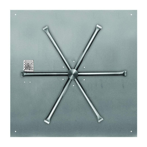
Section A Match Light (MT) Installation Flat disc’s are typically used with landscape blocks. The illustrations below show examples of possible installations. Fig’s 4, 5, and 6 show the use of the flex frame system which provides the ability to easily remove the disc if necessary. Fig.4 Show disc secured under stone caps. - Page 10 INSTALLING BURNER ORIFICE (OAS) Locate the burner nipple underneath the burner pan. Ensure the nipple from on Burner Pan the spur burner has gas rated Teflon tape Lock Nut wrapped around the threads. Thread the OAS (orifice air shutter) on to the nipple of the burning spur clockwise manner.
- Page 11 Spur Burner Non-Combustible Enclousure Flat Disc Key Valve Supply E-Stop PUSH TO STOP TURN TO START HOURS Key valve and flexible gas line are supplied; gas shut-off is not, but available in accessories page. Flex lines with flared fittings do not require Teflon tape or pipe compound.
-
Page 12: Operation & Lighting
OPERATION CAUTION: Children and adults should be alerted to the hazards on high surface temperatures and should stay away to avoid burns or clothing ignition. Young children should be carefully supervised when they are in the area of the appliance. WARNING: Do not use this appliance if any part has been under water. -
Page 13: Mt Troubleshooting/Maintenance
FIRE PIT MAINTENANCE 1. The fire pit should be inspected and cleaned before initial use at least annually by a qualified field service person. 2. Any component that is found faulty must be replaced with an approved component. 3. Any tampering or modifying with the fire pit is dangerous and voids all warranties. 4. -
Page 14: Expanded Mt Model View
Expanded View of Match Throw (MT) Fire Pits Fire Pit Pan Spur Burner / ” Washer Brass Nut OASNG# (Burner Ori ce) U3-8D-S (Fitting) Note: Use joint compound or Te on tape resistant to all T200-9898-46 gasses on all male NPT (Flex Connector) threads;... -
Page 15: Section B Thermocouple Manual Safety (Tmsi) Installation
Section B Thermocouple Manual Safety (TMSI) Installation Flat disc’s are typically used with landscape blocks. The illustrations below show examples of possible installations. Figs. 14, and 15 show the use of the flex frame system which provides the ability to easily remove the disc if necessary. Fig. - Page 16 INSTALLING GAS VALVE Piezo Ground Tab The gas valve is secured into the mounting plate with a nut. Fig. 17 shows an example of a typical installation. PIEZO48WH Illustration shows side view of valve and Piezo ignitor. Ignitor Module PIEZO25WH Bottom of Burner Pan Illustration above shows ground tab connection underneath the burner pan.
- Page 17 IGNITOR ALIGNMENT 1/8” Gap at Ignitor Probes It is important check that the ignitor probes be properly aligned overtop of the burner port holes and did not move during shipping. Use the Fig. 19 as a guide. Before lighting remove the screen cover of the ignition hood to burner and ensure the thermocouple is directly ⅛”...
-
Page 18: Operation & Lighting
OPERATION CAUTION: Children and adults should be alerted to the hazards on high surface temperatures and should stay away to avoid burns or clothing ignition. Young children should be carefully supervised when they are in the area of the appliance. WARNING: Do not use this appliance if any part has been under water. -
Page 19: Tmsi Troubleshooting/Maintenance
FIRE PIT MAINTENANCE 1. The fire pit should be inspected and cleaned before initial use at least annually by a qualified field service person. 2. Any component that is found faulty must be replaced with an approved component. 3. Any tampering or modifying with the fire pit is dangerous and voids all warranties. 4. -
Page 20: Expanded Tmsi Model View
Expanded View of Thermocouple Manual Safety (TMSI) Fire Pit Ignition Hood Spur Burner 7/8” Washer Ground Brass Nut OASNG# Note: Use joint compound or (Burner Ori ce) Te on tape resistant to all gasses on all male NPT U3-8D-S (Fitting) threads;... -
Page 21: Section C Thermocouple Flame Sense (Tfs) Installation
Section C Thermocouple Flame Sense (TFS) Installation Flat disc pans are typically uses with landscape blocks. The illustrations below show examples of possible installations. NOTE: Additional methods of supporting the center of the disc underneath or supporting an oversized opening are shown on page 9 in Figs. - Page 22 INSTALLING BATTERY PACK INTO WEATHERPROOF BOX After the weatherproof box location has been established and installed, run the black 4-PIN connector wire along with the red and black wires from the valve box into the weatherproof box. Connect red to red and black to black wires from the valve box to the wires of the battery pack.
- Page 23 Additional transmitters can be learned to this electronic module; up to a total of three transmitters are available. Contact Firegear to discuss additional transmitter options or see the accessory page of this instruction manual. Learning the new transmitters will require pressing the learn button on the module.
- Page 24 IGNITOR ALIGNMENT 1/8” Gap at Ignitor Probes It is important check that the ignitor probes be properly aligned overtop of the burner port holes and did not move during shipping. Use the Fig. 31 as a guide. Before lighting remove the screen cover of the ignition hood to burner and ensure the spark probes are directly overtop of a burner port ⅛”...
-
Page 25: Operation & Lighting
OPERATION CAUTION: Children and adults should be alerted to the hazards on high surface temperatures and should stay away to avoid burns or clothing ignition. Young children should be carefully supervised when they are in the area of the appliance. WARNING: Do not use this appliance if any part has been under water. -
Page 26: Tfs Troubleshooting/Maintenance
TROUBLE SHOOTING FOR TFS MODELS FAULT CODES The VCS-5000MODTC control module has built-in error detection for several common operating fault conditions. When the control module detects an error, it will emit a series of beeps. The beeping pattern will help to determine the cause of the operating fault Ignition Safety (Protection for ignition system): Error Code: One beep every one second. - Page 27 Thermal Safety (Overheat Protection): Error Code: 4 Beeps every 2 seconds. Description of Fault: Warn users that the modules internal temperature exceeds 170°F. How to Clear: Module’s internal temperature must cool to below 160°F and then press ON button. What to Check: Ensure that there is proper ventilation to the control module.
- Page 28 ADDITIONAL TROUBLE SHOOTING Symptom Remedy Fire Pit 1. Bleed gas line. Won’t Light 2. Ensure all gas lines are turned ON. 3. Ensure there is not too much media overtop the burner, it can inhibit the gas flow. Too little or no media can also contribute to non-lighting. 4.
-
Page 29: Expanded Tfs Model View
Expanded View of Thermocouple Flame Sense (TFS) Fire Pits Spur Burner Ignition Hood Orange ⁄ ” Washer Ignition Wire Brass Nut Flat Disc Pan OAS-NG# (1) ⁄ ” Washer (Burner Ori ce) Thermocouple & ½” Coupler Ground Wires Battery Pack Black Wire Valve Box: (Gas valve,control module... -
Page 30: Replacement Parts
SQUARE FLAT REPLACEMENT PARTS PILOT ADJ PILOT MAIN Drawings are not to scale POWER Requires 4-AA 1.5V alkaline batteries Slide Switch to Latching Solenoid Square Flat Disc Fire Pits REV. 6-25-19 Page 30... -
Page 31: Replacement Parts List
SQUARE FLAT REPLACEMENT PARTS LIST Qty. Item Part Number Description TMSI 25-inch Square Flat Stainles Disc PAN-SS25SF 30-inch Square Flat Stainless Disc PAN-SS29D 34-inch Square Flat Stainless Disc PAN-SS34D 22-inch Burning Spur (used on all flat square pans) B-SPUR-22 ½” NPS Brass Mounting Nut 105-8 7/8”... - Page 32 GROUNDTAB 6-32 x 1” Flat Head Phillips Screw - Holds WP Lid to WP-JBOX SCREW6-32X1PHFHZ (not shown) FOR TECHNICAL SERVICE, CALL: (855) 498-8324 Firegear Outdoors 9230 Conservation Way Fort Wayne, IN 46809 Sales: (888) 672-8929 Sales Support: (888) 699-6167 Canadian Inquires: (877) 472-3923 Web Site: www.firegearoutdoors.com...
-
Page 33: Optional Accessories
OPTIONAL ACCESSORIES The following accessories are available from your local Firegear dealer/distributor. Each accessory comes with a separate installation manual. Read each instruction thoroughly before installing. Media Media Media Lava Stones: 1” to 2” size (50 lbs) Lava Boulders: 6” to 12” size (30lbs) Lava Rock: 1”... - Page 34 The TMS valve bracket can be oriented in different positions to accommodate different installations. Once the bracket and knob are installed, the knob may not be oriented in a convenient position to easily read. If this is the case, we have provided a label that can be placed over top of the existing knob for the user to easily know which way to turn the control knob to light a fire pit.
- Page 35 Square Flat Disc Fire Pits REV. 6-25-19 Page 35...
- Page 36 Optional Cutout Template for TMSI Face Plate This fire pit instruction provides an option to mount the TMSI face plate to concrete board. Use the template above to complete the installation. The TMSI face plate can be mounted vertically or horizontally. Our suggestion is to attach the face plate in a horizontal position with the gas valve on the left side.
- Page 37 Lava Rock and Lava Stones are not covered by warranty For Commercial applications, the liability of Firegear Outdoors End User must provide a bill of sale, canceled check, or payment is limited to the express terms of this warranty. We expressly...
- Page 38 Having problems getting the fire pit to operate? Don’t leave the job site! We want to help! Call 855.498.8324 for Technical Support between the hours of 8:00AM to 5:00PM EST. Text photos to 260.255.5750 or e-mail photos to support@skytechpg.com. BEFORE YOU CALL WE WILL NEED THIS INFORMATION Model Number: ___________________________ Serial Number: ___________________________ How long is the gas line run? Nat Gas ____ LP Gas ____...
Need help?
Do you have a question about the FPB-25SFBSMT-N and is the answer not in the manual?
Questions and answers