Advertisement
INSTALLATION
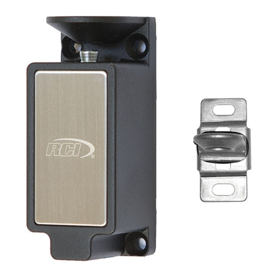
RCI 3513-DM
DUAL MONITOR CABINET LOCK
Instructions For Lock Mode Change
1. Remove the 2 screws on the bottom.
2. Remove base plate and solenoid.
3. Turn assembly 180º and install into
housing.
NOTE: Care should be taken to
prevent damage to switch lever.
4. Insert the two screws.
1-1/4"
(31mm)
IS3513DM
Door Monitor
Switch
Locking Pin
Monitor Switch
1-1/4"
(32mm)
3-11/16"
(93mm)
© 2018 dormakaba Canada Inc
www.dormakaba.us • Phone: 1.800.265.6630 • Fax: 1.800.482.9795 • E-mail: sales_RCI@dormakaba.com
N/C
C
N/O
Fail Secure
N/C
C
N/O
1-3/16"
(30mm)
2-3/4"
(70mm)
7/8"
(22mm)
Connect to
appropriate
DC voltage
(See wiring diagram)
Fail Safe
PCN18041
R12-18TG
Advertisement
Table of Contents

Subscribe to Our Youtube Channel
Related Manuals for Dormakaba RCI 3513-DM


Summary of Contents for Dormakaba RCI 3513-DM
- Page 1 DC voltage Locking Pin (See wiring diagram) Monitor Switch 1-1/4" 1-3/16" (32mm) (30mm) 1-1/4" (31mm) 3-11/16" 2-3/4" (93mm) (70mm) 7/8" (22mm) © 2018 dormakaba Canada Inc PCN18041 IS3513DM www.dormakaba.us • Phone: 1.800.265.6630 • Fax: 1.800.482.9795 • E-mail: sales_RCI@dormakaba.com R12-18TG...
- Page 2 Door Monitor Switch Wiring Diagram Cabinet Lock Dual Voltage Wiring Diagram 125VAC; 3A / 30VDC; 2A 24VDC (100mA) ORANGE 24VDC BLUE BLUE YELLOW BLACK BLACK © 2018 dormakaba Canada Inc www.dormakaba.us • Phone: 1.800.265.6630 • Fax: 1.800.482.9795 • E-mail: sales_RCI@dormakaba.com...
Need help?
Do you have a question about the RCI 3513-DM and is the answer not in the manual?
Questions and answers