Table of Contents
Advertisement
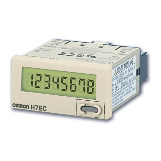
Self-powered Totalizer
H7E
Compact Economical Totalizer with High Visibility
Available with Backlit LCD Display
• Large display with 8.6-mm character height.
• Includes new models with backlight for improved visibility in dimly lit places. (Requires 24-VDC power supply.)
• Black and light-gray cases now available.
• PNP/NPN universal DC voltage input types now available.
• Battery is replaceable for Totalizer reuse and conservation of the environment.
• Key-protect switch to prevent faulty reset key operation.
• Dual operation mode.
• Front face compatible with NEMA4/IP66.
• Short body, all models have a depth of 48.5 mm.
• Finger protection terminal block conforms to VDE0106 Part100.
• Conforms to UL, CSA, and CE marking.
Conforms to EN61010-1 (pollution degree 2/overvoltage category III.)
• Conforms to EMC standards and EN61326, thus allowing use in residential, commercial and light- and heavy-industry environ-
ments.
• Six-language instruction manual provided.
• PCB-mounting models available. (Requires 3-V power supply.)
I Broad Line-up of the H7E Series
H7EC
Total Counter
• 8-digit
Self-powered Totalizers
H7EC.....................................................................................................................
H7ET .....................................................................................................................
H7ER.....................................................................................................................
H7E@-N@P ...........................................................................................................
Common to All Totalizers
Accessories...........................................................................................................
Precautions ...........................................................................................................
H7E
H7ET
Time Counter
• 999999.9h/
3999d23.9h
• 999h59min59s/
9999h59.9min
Contents
RC
H7ER
Tachometer
• 1,000 s
-1
with
1 pulse/rev. encoder
• 1,000.0 s
-1
with
10 pulse/rev. encoder
• 1,000 min
-1
with
60 pulse/rev. encoder
• 10,000 min
-1
with
60 pulse/rev. encoder
• 1,000.0 min
-1
with
600 pulse/rev. encoder
C-17
C-25
C-31
C-37
C-39
Self-powered Totalizer
H7E@-N@P
PCB-mounting Counter
• Total Counter (8-digit)
• Time Counter (999999.9h)
C-9
H7E
C-7
Advertisement
Chapters
Table of Contents


Need help?
Do you have a question about the H7EC and is the answer not in the manual?
Questions and answers
what is the battery replacement procedure ?
The battery replacement procedure for the Omron H7EC is as follows:
1. Use a tool to pry open the lift-tab on the case.
2. Pull the body out of the outer case.
3. Lift the battery by the edge and remove it without touching the display area or internal parts.
4. Wipe the back of the new battery before inserting it.
5. Ensure the + and - terminals are correctly oriented.
6. Re-insert the body into the case and confirm the case is securely held by the lift-tab.
7. Press the Reset Key before use (not required for H7ER-N, -NV, -NV1 models).
This answer is automatically generated