Advertisement
Quick Links
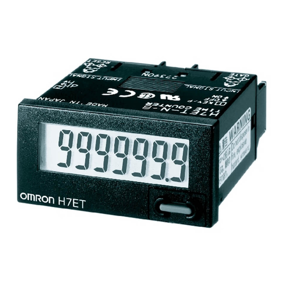
Self-powered Totalizer
New H7E
Compact Economical Totalizer with High Visibility
Available with Backlit LCD Display
• Large display with 8.6-mm character height.
• Includes new models with backlight for improved visibility in dimly lit places. (Requires 24-VDC power supply.)
• Black and light-gray cases now available.
• PNP/NPN universal DC voltage input types now available.
• Battery is replaceable for Totalizer reuse and conservation of the environment.
• Key-protect switch to prevent faulty reset key operation.
• Dual operation mode.
• Front face compatible with NEMA4/IP66.
• Short body, all models have a depth of 48.5 mm.
• Finger protection terminal block conforms to VDE0106, Part100.
• Conforms to UL, CSA, and CE marking.
Conforms to EN61010-1 (pollution degree 2/overvoltage category III.)
• Conforms to EMC standards and EN61326, thus allowing use in residential, commercial and light- and heavy-industry environ-
ments.
• Six-language instruction manual provided.
• PCB-mounting models available. (Requires 3-V power supply.)
■ Broad Line-up of the New H7E Series
New H7EC
Total Counter
• 8-digit
Self-powered Totalizers
Common to All Totalizers
Arrow.com.
Downloaded from
New H7ET
Time Counter
• 999999.9h/
3999d23.9h
• 999h59min59s/
9999h59.9min
H7EC.....................................................................................................................
H7ET .....................................................................................................................
H7ER.....................................................................................................................
H7E@-N@P ...........................................................................................................
Accessories ...........................................................................................................
Precautions ...........................................................................................................
New H7E
New H7ER
Tachometer
• 1,000 s
-1
with
1 pulse/rev. encoder
• 1,000.0 s
-1
with
10 pulse/rev. encoder
• 1,000 min
-1
with
60 pulse/rev. encoder
• 10,000 min
-1
with
60 pulse/rev. encoder
• 1,000.0 min
-1
with
600 pulse/rev. encoder
Contents
CSM_H7E_-N_DS_E_9_3
New H7E@-N@P
PCB-mounting Counter
• Total Counter (8-digit)
• Time Counter (999999.9h)
2
9
16
22
27
29
1
Advertisement

Related Manuals for Omron NNew H7E Series


Summary of Contents for Omron NNew H7E Series
- Page 1 Self-powered Totalizer New H7E CSM_H7E_-N_DS_E_9_3 Compact Economical Totalizer with High Visibility Available with Backlit LCD Display • Large display with 8.6-mm character height. • Includes new models with backlight for improved visibility in dimly lit places. (Requires 24-VDC power supply.) •...
- Page 2 AC/DC multi-voltage input 2. Case Color None: Light gray Black Note: Estimates can be provided for coatings and other specifications that are not given in the datasheet. Ask your OMRON representative for details. Ordering Information ■ Total Counters Count input Max.
- Page 3 New H7EC Specifications ■ General Item H7EC-NV-@ H7EC-NFV-@ H7EC-N-@ H7EC-NV-@H Operating mode Up type Mounting method Flush mounting External connections Screw terminals, optional Wire-wrap Terminals (see note 1) Reset External/Manual reset Number of digits Count input PNP/NPN universal DC voltage in- AC/DC multi-voltage input No-voltage input Display...
- Page 4 New H7EC ■ Characteristics Item H7EC-NV-@ H7EC-NFV-@ H7EC-N-@ H7EC-NV-@H Insulation resistance 100 MΩ min. (at 500 VDC) between 100 MΩ min. (at 500 VDC) between 100 MΩ min. (at 500 VDC) between current-carrying metal parts and ex- current-carrying metal parts and ex- current-carrying metal parts and ex- posed non-current-carrying metal posed non-current-carrying metal parts...
- Page 5 New H7EC Connections ■ Terminal Arrangement Bottom view: View of the Total Counter rotated horizontally 180° Backlight Model No-backlight Model Backlight 24 VDC Count Reset Count Reset input input input input ■ Connections H7EC Total Counter PNP/NPN Universal DC Voltage Input Model With Backlight 1.
- Page 6 Note: Use Relays and Switches that have high contact 2. Solid-state Input reliability because the current flowing from terminals Open collector of a Open collector of a 1 or 3 is small. It is recommended that OMRON's PNP transistor PNP transistor G3TA-IA/ID be used as the SSR. Input 2.
- Page 7 New H7EC Operation ■ Operating Modes H7EC Total Counter Incrementing Operation (Up) Reset Count input Full-scale (Full-scale −1) Counting display values Nomenclature Front view Reset Key H7EC Reset the count value. Not operable under key-protect. Key-protect Switch Counting speed switch The Reset Key is not operable while the For all models except for H7EC-NFV-@.
- Page 8 New H7EC Dimensions Note: All units are in millimeters unless otherwise indicated. H7EC-N M3.5 terminal screw Panel Cutout Separate mounting 40 min. +0.5 +0.5 22.2 Dimensions with Y92F-34 Flush Mounting Bracket Dense mounting +1.0 (48 Units − 2.5) +0.5 22.2 Waterproofing is not possible for dense mounting •...
- Page 9 None: 7-segment LCD without backlight 7-segment LCD with backlight None: 999999.9h/3999d23.9h 999h59m59s/9999h59.9m Note: Estimates can be provided for coatings and other specifications that are not given in the datasheet. Ask your OMRON representative for details. Ordering Information ■ Time Counters Timer input...
- Page 10 New H7ET Specifications ■ General Item H7ET-NV-@ H7ET-NFV-@ H7ET-N-@ H7ET-NV1-@ H7ET-NFV1-@ H7ET-N1-@ H7ET-NV-@H H7ET-NV1-@H Operating mode Accumulating Mounting method Flush mounting External connections Screw terminals Reset External/Manual reset Display 7-segment LCD with or without backlight, zero suppression (character height: 8.6 mm) (see note 1) Number of digits 0.0h to 999999.9h ←→...
- Page 11 New H7ET ■ Characteristics Item H7ET-NV@-@ H7ET-NFV@-@ H7ET-N@-@ H7ET-NV@-H@ Time accuracy ±100 ppm (25°C) Insulation resistance 100 MΩ min. (at 500 VDC) between 100 MΩ min. (at 500 VDC) between 100 MΩ min. (at 500 VDC) between current-carrying metal parts and ex- current-carrying metal parts and ex- current-carrying metal parts and ex- posed non-current-carrying metal...
- Page 12 New H7ET Connections ■ Terminal Arrangement Bottom view: View of the Time Counter rotated horizontally 180° Backlight Model No-backlight Model Backlight 24 VDC Timer Reset Timer Reset input input input input ■ Connections H7ET Time Counter PNP/NPN Universal DC Voltage Input Model With Backlight 1.
- Page 13 3 is as small as approx. 10 µA. It is recommended Open collector of a Open collector of a PNP transistor PNP transistor that OMRON's G3TA-IA/ID be used as the SSR. Input 2. Solid-state Input Reset (Open Collector Input of an NPN Transistor)
- Page 14 New H7ET Operation ■ Operating Modes H7ET Time Counter Incrementing Operation (Up) Reset Timer input Internal clock timer value Full-scale (Full-scale −0.1 (1)) Timer display values Nomenclature Front view Location to Attach Unit Label Attach the correct unit label for the time range Reset Key H7ET that is set.
- Page 15 New H7ET Dimensions Note: All units are in millimeters unless otherwise indicated. H7ET-N Panel Cutout Separate mounting 40 min. +0.5 Dimensions with Y92F-34 Flush Mounting Bracket +0.5 22.2 Dense mounting +1.0 (48 Units − 2.5) +0.5 22.2 Waterproofing is not possible for dense mounting •...
- Page 16 None: 7-segment LCD without backlight 5 digits 7-segment LCD with backlight Note: Estimates can be provided for coatings and other specifications that are not given in the datasheet. Ask your OMRON representative for details. Ordering Information ■ Tachometers Count input Display Max.
- Page 17 New H7ER Specifications ■ General Item H7ER-NV-@ H7ER-N-@ H7ER-NV1-@ H7ER-NV-@H H7ER-NV1-@H Operating mode Up type Mounting method Flush mounting External connections Screw terminals, Wire-wrap Terminals (see note 3) Display 7-segment LCD with or without backlight, zero suppression (character height: 8.6 mm) (see note 4) Number of digits Count input PNP/NPN universal DC...
- Page 18 New H7ER ■ Characteristics Item H7ER-NV@-@ H7ER-N-@ H7ER-NV@-@H Insulation resistance 100 MΩ min. (at 500 VDC) between current-carrying 100 MΩ min. (at 500 VDC) between current-carrying metal parts and exposed non-current-carrying metal metal parts and exposed non-current-carrying metal parts, and between the backlight power supply and parts count input terminals/reset terminals for backlight models...
- Page 19 New H7ER Connections ■ Terminal Arrangement Bottom view: View of the Tachometer rotated horizontally 180° Backlight Model No-backlight Model Backlight 24 VDC Pulse Pulse input input ■ Connections H7ER Tachometer Note: Select input transistors according to the following: Dielectric strength of the collector ≥ 50 V Leakage current <...
- Page 20 New H7ER Operation ■ Operating Modes H7ER Tachometer Incrementing Operation Within Unit Time (Up) Count period Count period 0.25 s (1 s) (1 s) Internal gate Refresh Display refreshed Counter reset Internal count value Previous count Number display value display Display refreshed Display refreshed every 1.25 s...
- Page 21 New H7ER Dimensions Note: All units are in millimeters unless otherwise indicated. H7ER-N Panel Cutout Separate mounting 40 min. +0.5 +0.5 22.2 Dimensions with Y92F-34 Flush Mounting Bracket Dense mounting +1.0 (48 Units − 2.5) +0.5 22.2 Waterproofing is not possible for dense mounting •...
- Page 22 • Dedicated for use on PCB. • Total Counters and Time Counter available. For the most recent information on models that have been certified for safety standards, refer to your OMRON website. Model Number Structure ■ Model Number Legend 1. Function...
- Page 23 H7E@-N@P Specifications ■ General Item Total Counter Time Counter H7EC-NP H7EC-NLP H7ET-NP Operating mode Up type Mounting method Direct mounting on PC Board or mounting on 28-pin socket Reset External reset, Power-OFF reset Number of digits Time range 0.0h to 999999.9h Max.
- Page 24 H7E@-N@P Connections ■ Terminal Arrangement 3-VDC external H7EC-N@P H7ET-NP 3-VDC external power supply power supply Reset Reset Timer Count Bottom view Bottom view input input input input 28 26 17 15 28 26 17 15 Top view Top view COUNTS COUNTS omronH7EC omronH7ET...
- Page 25 H7E@-N@P Input Connections Solid State Input Open-collector Transistor Input Input Connection Contact Input H7E@-N@P Relay Relay H7E@-N@P Reset input Count/Timer input Reset input Count/Timer input TTL or C-MOS IC Input TTL or C-MOS IC TTL or C-MOS IC H7E@-N@P When the H7EC-NP is used, relay chattering may be counted. Use the H7EC-NLP, one of the low-speed input models.
- Page 26 H7E@-N@P Dimensions Note: All units are in millimeters unless otherwise indicated. DIP Terminal PCB Processing Dimensions H7EC-N@P (Soldering Surface) Section occupied by the Counter Eight, 0.8 dia. DIP terminal x 8 Base 17.3 max. H7ET-NP Note: Processing dimensions are for 28-pin IC socket. Arrow.com.
- Page 27 H7E@-N@P Accessories (Order Separately) (Common) ■ New H7E (Except for PCB-mounting Counter) The New H7E models are supplied with a mounting bracket (Y92F-34) and nut. Additionally, the Y92F-75/-76/-77B Flush Mounting Adapters shown here allow the New H7E models to be fitted to existing panel cutouts. Y92F-35 Compact Flush Mounting Bracket Panel Cutout Single mounting...
- Page 28 H7E@-N@P Y92S-37 Wire-wrap Terminal (Set of Two Terminals) 44.8 Wire-wrap terminal (1 × 1 mm) 48.5 17.1 When using the Wire-wrap Terminal, be sure to use the correct wires Wire Sleeve Wrapped state and peripheral devices. (The correct wires, bits and sleeves are AWG22 Normal shown in the table on the right.)
- Page 29 H7E@-N@P Precautions (Common) Refer to Safety Precautions for All Counters. ■ New H7E (Except for PCB-mounting Counter) !WARNING !CAUTION This product has a built-in lithium battery. Do not short-circuit the + If a voltage other than the rated one is applied, internal elements may and −...
- Page 30 • When connecting count/timer input from an SSR to the Counter to More than One H7E Counter at a that operates with AC/DC voltage input, use OMRON’s G3TA-IA/ID Time SSR (for DC) whose leakage current is 0.1 mA max. or connect a bleeder resistor in parallel to the input circuit of the Counter.
- Page 31 H7E@-N@P 7. Press the Reset Key before use (not necessary for H7ER-N,-NV,- EN/IEC Standards NV1). (5) The count or timer input, reset input, and backlight power supply ter- Tool minals of the no-voltage input or PNP/NPN universal DC voltage input models (H7E@-N,-N1, H7E@-NV(-H),-NV1(-H)) are not iso- lated.
- Page 32 • No user-serviceable parts. 1. Minimize the wiring (less than 50 mm) from the H7E@-N@P to the • Return to OMRON for all repairs. power supply section. 2. Avoid placing the H7E@-N@P power, timer, counter, or reset input circuit in parallel with circuits that consume large currents, partic- ularly on the positive side.
- Page 33 (a) Exclusive Warranty. Omron’s exclusive warranty is that the Products will be free from defects in materials and workmanship for a period of twelve months from the date of sale by Omron (or such other period expressed in writing by Omron). Omron disclaims all other warranties, express or implied.
Need help?
Do you have a question about the NNew H7E Series and is the answer not in the manual?
Questions and answers