Table of Contents
Advertisement
Quick Links
The DS280MB810 is an 8 Channel Linear Repeater with the ability to extend the reach and robustness of
high speed serial links for up to 28 Gbps interfaces. Simplified equalization control, low power
consumption, and ultra-low additive jitter make the DS280MB810 ideal for front-port interfaces such as
100G-SR4/LR4/CR4 and backplane applications. The small 8 mm x 13 mm package easily fits behind
numerous standard front-port connectors, including SFP28, QSFP28, CFP2/CFP4, and CDFP, without the
need for a heat sink. The optimized package dimensions, high-speed signal escape, and the pin-
compatible retimer portfolio make the DS280MB810 well-suited for high-density backplane and front port
applications. The DS280MB810 can be configured via the default SMBus slave mode or with an external
EEPROM. With this kit, users can quickly evaluate the linear equalizer's performance.
SNLU213A – October 2016 – Revised September 2019
Submit Documentation Feedback
DS280MB810EVM User's Guide
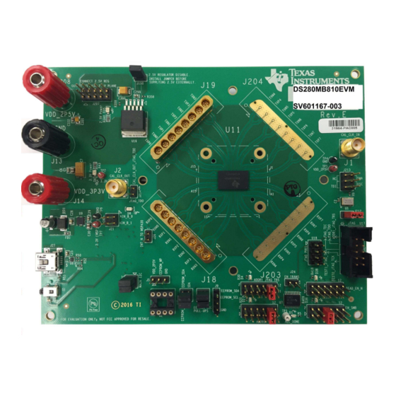
Figure 1. DS280MB810EVM.
Copyright © 2016–2019, Texas Instruments Incorporated
SNLU213A – October 2016 – Revised September 2019
DS280MB810EVM User's Guide
User's Guide
1
Advertisement
Table of Contents

Related Manuals for Texas Instruments DS280MB810EVM


Summary of Contents for Texas Instruments DS280MB810EVM
-
Page 1: Ds280Mb810Evm
The DS280MB810 can be configured via the default SMBus slave mode or with an external EEPROM. With this kit, users can quickly evaluate the linear equalizer’s performance. Figure 1. DS280MB810EVM. SNLU213A – October 2016 – Revised September 2019 DS280MB810EVM User’s Guide Submit Documentation Feedback Copyright © 2016–2019, Texas Instruments Incorporated... -
Page 2: Table Of Contents
Settings and Measurements for CAUI-4 and nPPI with 10in Input Channel and Minimal Output Channel Trademarks All trademarks are the property of their respective owners. DS280MB810EVM User’s Guide SNLU213A – October 2016 – Revised September 2019 Submit Documentation Feedback Copyright © 2016–2019, Texas Instruments Incorporated... -
Page 3: Features
NOTE: Huber+Suhner MXP cable assembles are not provided with this EVM. Users are expected to provide cabling to connect to other boards and test equipment. For MXP cabling recommendations please see Section SNLU213A – October 2016 – Revised September 2019 DS280MB810EVM User’s Guide Submit Documentation Feedback Copyright © 2016–2019, Texas Instruments Incorporated... -
Page 4: Setup
Figure 2. DS280MB810EVM Block Diagram. Modes of Programmable Communication The DS280MB810EVM can be programmed in one of two modes: 1. SMBus Mode – Provides full access to the DS280MB810 status and control settings via the on-board USB2ANY. ADDR0 and ADDR1 pins are used to set the SMBus slave address. -
Page 5: Description Of Smbus And Eeprom Connections
Common Ground +3.3 V Input Software Setup with SigCon Architect The general procedure for setting up and testing with the DS280MB810EVM is as follows. For hardware setup and connections in the steps below, reference the illustrations in Figure 2 Figure 4 to implement the appropriate setup. -
Page 6: Repeater Profile Updater Installers
NOTE: The Reference Clock is not required for DS280MB810 operation. 5. Install the appropriate jumper shunts to operate in default configuration with VDD = 2.5 V in SMBus Slave Mode or EEPROM Master Mode. The default configuration for the DS280MB810EVM operates in SMBus Slave Mode, as shown below in Figure •... -
Page 7: Ds280Mb810Evm Default Configuration
Figure 4 (the top right pin). 6. Connect a PC to DS280MB810EVM with a USB-to-Mini cable via J27. 7. Open SigCon Architect, and navigate to the “Configuration” page of DS280MB810 via the “Selection” column. Choose “Slave Address” “0x30” from the drop down menu. Verify the “USB2ANY Details”... -
Page 8: Sigcon Architect Configuration Page
Write Register: Type the writable address in the “Current Address” text box, and type the data to write to this address in the “Data” text box. Click “Write Register.” Figure 6. SigCon Architect Low Level Page. DS280MB810EVM User’s Guide SNLU213A – October 2016 – Revised September 2019 Submit Documentation Feedback Copyright © 2016–2019, Texas Instruments Incorporated... -
Page 9: Sigcon Architect High Level Page: Device Status
The displayed values are the current settings programmed on the device. Step 10 describes how to edit these settings. Figure 7. SigCon Architect High Level Page: Device Status. SNLU213A – October 2016 – Revised September 2019 DS280MB810EVM User’s Guide Submit Documentation Feedback Copyright © 2016–2019, Texas Instruments Incorporated... -
Page 10: Sigcon Architect High Level Page: Block Diagram
– Driver VOD and EQ DC Gain settings can be changed on this page. The Approximate DC gain in dB ranges from -4.5 to +5.0 dB. Figure 8. SigCon Architect High Level Page: Block Diagram. DS280MB810EVM User’s Guide SNLU213A – October 2016 – Revised September 2019 Submit Documentation Feedback Copyright © 2016–2019, Texas Instruments Incorporated... -
Page 11: Sigcon Architect High Level Page: Crossspoint Switch
– Lane Crossing: Swaps the outputs within the 2x2 crosspoint Figure 9. SigCon Architect High Level Page: Crossspoint Switch. Figure 10. SigCon Architect High Level Page: Crosspoint Switch. SNLU213A – October 2016 – Revised September 2019 DS280MB810EVM User’s Guide Submit Documentation Feedback Copyright © 2016–2019, Texas Instruments Incorporated... - Page 12 EEPROM Size = 3 Bytes (Base Header) + Number of devices x 12 Bytes/device (Address Header) + Number of slots x 66 Bytes/slot (Data) DS280MB810EVM User’s Guide SNLU213A – October 2016 – Revised September 2019 Submit Documentation Feedback Copyright © 2016–2019, Texas Instruments Incorporated...
-
Page 13: Sigcon Architect Eeprom Page
NOTE: Profile versions 1.0.1.0 and earlier do not support CRC with EEPROM size set to larger 256 bytes. This feature will be available in future releases. SNLU213A – October 2016 – Revised September 2019 DS280MB810EVM User’s Guide Submit Documentation Feedback Copyright © 2016–2019, Texas Instruments Incorporated... -
Page 14: Example Hardware Test Setup
Example Hardware Test Setup In order to test the functionality of the DS280MB810EVM, connect TXP0 and TXN0 with MXP cable assemblies to DC blocking capacitors and a Keysight DCA-x Oscilloscope or equivalent (50 Ω terminated). Connect the data source, high speed BERT or other device with MXP cable assemblies to RXP0 and RXN0. -
Page 15: 25.78125 Gbps Caui-4 Eye Mask With 5In Input Channel And Minimal Output Channel
EQ DC Gain Mode Total Jitter @ 1E-15 11.9 ps 13.0 ps Differential Eye Height @ 1E-15 338 mV 544 mV Mask violations SNLU213A – October 2016 – Revised September 2019 DS280MB810EVM User’s Guide Submit Documentation Feedback Copyright © 2016–2019, Texas Instruments Incorporated... -
Page 16: 25.78125 Gbps Caui-4 Eye Mask With 10In Input Channel And Minimal Output Channel
EQ DC Gain Mode Total Jitter @ 1E-15 11.3 ps 13.5 ps Differential Eye Height @ 1E-15 210 mV 532 mV Mask violations DS280MB810EVM User’s Guide SNLU213A – October 2016 – Revised September 2019 Submit Documentation Feedback Copyright © 2016–2019, Texas Instruments Incorporated... -
Page 17: Common Problems And Possible Solutions
File. Another interface adapter must be used to burn Hex File to EEPROM the Hex File to the EPPROM. (i.e. AARDVARK or with SigCon Architect. equivalent ). SNLU213A – October 2016 – Revised September 2019 DS280MB810EVM User’s Guide Submit Documentation Feedback Copyright © 2016–2019, Texas Instruments Incorporated... -
Page 18: Bill Of Materials
7007 POST BINDING ECON NYLON-INS BLK 7007, Black J14,J208 Binding Post, Keystone 7006 POST BINDING ECON NYLON-INS RED 7006, Red DS280MB810EVM User’s Guide SNLU213A – October 2016 – Revised September 2019 Submit Documentation Feedback Copyright © 2016–2019, Texas Instruments Incorporated... - Page 19 IC SOCKET 8PIN .300 SOLDER TAIL MSP430 MSP430F5529IPN or IC MCU 16BIT 128KB FLASH 80LQFP MSP430F5529IPNR TXB0108 TXB0108PWR IC 8-BIT TRNSTR 15KV ESD 20TSSOP SNLU213A – October 2016 – Revised September 2019 DS280MB810EVM User’s Guide Submit Documentation Feedback Copyright © 2016–2019, Texas Instruments Incorporated...
- Page 20 DS280MB810 TPS75725 TPS75725KTTRG3 IC REG LDO 2.5V 3A DDPAK 24.0 MHz ECS-240-20-5PX-TR CRYSTAL 24.000MHZ 20PF SMD SV601167 REVE BOARD PCB DS280MB810EVM User’s Guide SNLU213A – October 2016 – Revised September 2019 Submit Documentation Feedback Copyright © 2016–2019, Texas Instruments Incorporated...
-
Page 21: Evm Cable Assemblies
EVM Cable Assemblies www.ti.com EVM Cable Assemblies The DS280MB810EVM uses Huber+Suhner 1x8 MXP cable assemblies. For Huber+Suhner quotes or additional information requests, please contact: Info.us@hubersuhner.com HUBER+SUHNER Inc. 8530 Steele Creek Place Drive, Suite H Charlotte-NC- 28273 +1 704-790-7300 Below are suggested part numbers that can be used with this EVM. Other part numbers and cable lengths have not been tested, but can be considered for use. - Page 22 NOTE: Page numbers for previous revisions may differ from page numbers in the current version. Changes from Original (October 2016) to A Revision ....................Page ........................• Initial public release Revision History SNLU213A – October 2016 – Revised September 2019 Submit Documentation Feedback Copyright © 2016–2019, Texas Instruments Incorporated...
- Page 23 STANDARD TERMS FOR EVALUATION MODULES Delivery: TI delivers TI evaluation boards, kits, or modules, including any accompanying demonstration software, components, and/or documentation which may be provided together or separately (collectively, an “EVM” or “EVMs”) to the User (“User”) in accordance with the terms set forth herein.
- Page 24 www.ti.com Regulatory Notices: 3.1 United States 3.1.1 Notice applicable to EVMs not FCC-Approved: FCC NOTICE: This kit is designed to allow product developers to evaluate electronic components, circuitry, or software associated with the kit to determine whether to incorporate such items in a finished product and software developers to write software applications for use with the end product.
- Page 25 www.ti.com Concernant les EVMs avec antennes détachables Conformément à la réglementation d'Industrie Canada, le présent émetteur radio peut fonctionner avec une antenne d'un type et d'un gain maximal (ou inférieur) approuvé pour l'émetteur par Industrie Canada. Dans le but de réduire les risques de brouillage radioélectrique à...
- Page 26 www.ti.com EVM Use Restrictions and Warnings: 4.1 EVMS ARE NOT FOR USE IN FUNCTIONAL SAFETY AND/OR SAFETY CRITICAL EVALUATIONS, INCLUDING BUT NOT LIMITED TO EVALUATIONS OF LIFE SUPPORT APPLICATIONS. 4.2 User must read and apply the user guide and other available documentation provided by TI regarding the EVM prior to handling or using the EVM, including without limitation any warning or restriction notices.
- Page 27 Notwithstanding the foregoing, any judgment may be enforced in any United States or foreign court, and TI may seek injunctive relief in any United States or foreign court. Mailing Address: Texas Instruments, Post Office Box 655303, Dallas, Texas 75265 Copyright © 2019, Texas Instruments Incorporated...
- Page 28 TI products. TI’s provision of these resources does not expand or otherwise alter TI’s applicable warranties or warranty disclaimers for TI products. Mailing Address: Texas Instruments, Post Office Box 655303, Dallas, Texas 75265 Copyright © 2019, Texas Instruments Incorporated...
Need help?
Do you have a question about the DS280MB810EVM and is the answer not in the manual?
Questions and answers