Table of Contents
Advertisement
Quick Links
The DS250DF230 is a four-channel multi-rate retimer with integrated signal conditioning. It is used to
extend the reach and robustness of long, lossy, crosstalk-impaired high-speed serial links while achieving
a bit error rate (BER) of 10-15 or less. Each channel of the DS250DF230 independently locks to serial
data rates in a continuous range from 19.6 Gbps to 25.8 Gbps or to any supported sub-rate (÷2 and ÷4).
The DS250DF230 has a single power supply and minimal need for external components. These features
reduce PCB routing complexity and BOM cost. The advanced equalization features of the DS250DF230
include a low-jitter 3-tap transmit finite impulse response (FIR) filter, an adaptive continuous-time linear
equalizer (CTLE), and an adaptive decision feedback equalizer (DFE). This enables reach extension for
lossy interconnect and backplanes with multiple connectors and crosstalk. The integrated CDR function is
ideal for front-port optical module applications to reset the jitter budget and retime the high-speed serial
data. The DS250DF230 implements 2x2 cross-point on each channel pair, providing the host with both
lane crossing and fanout options.
The DS250DF230 can be configured via the default SMBus slave mode or with an external EEPROM. Up
to 16 devices can share a single EEPROM. A non-disruptive on-chip eye monitor and PRBS generator
and checker functions allow for in-system diagnostics. With this kit, users can quickly evaluate the
DS250DF230 retimer performance.
SNLU238A – August 2018 – Revised September 2019
Submit Documentation Feedback
DS250DF230EVM User's Guide
Copyright © 2018–2019, Texas Instruments Incorporated
SNLU238A – August 2018 – Revised September 2019
DS250DF230EVM User's Guide
User's Guide
1
Advertisement
Table of Contents

Related Manuals for Texas Instruments DS250DF230EVM


Summary of Contents for Texas Instruments DS250DF230EVM
- Page 1 16 devices can share a single EEPROM. A non-disruptive on-chip eye monitor and PRBS generator and checker functions allow for in-system diagnostics. With this kit, users can quickly evaluate the DS250DF230 retimer performance. SNLU238A – August 2018 – Revised September 2019 DS250DF230EVM User’s Guide Submit Documentation Feedback Copyright © 2018–2019, Texas Instruments Incorporated...
-
Page 2: Table Of Contents
Environmental (RoHS and REACH) ....................EVM Cable Assemblies List of Figures ......DS250DF230EVM, Showing Connections for Power, Signal, and USB Communications ................Download SigCon Architect from www.ti.com ..................SigCon Architect Start-Up Screen Capture Illustrating the “Manage Devices” Pop-Up Window for Adding New Part Numbers to the ...................... -
Page 3: Hardware Description And Setup
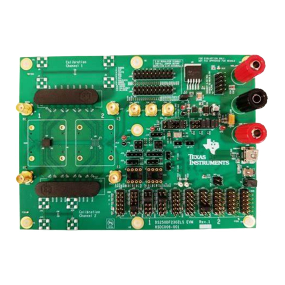
3. Connect 3.3V power (2A max) as shown below. The EVM has an on-board 3.3V-to-2.5V regulator to supply the Retimer with the required 2.5V. Make sure multiple jumpers are used on header J10. Figure 1. DS250DF230EVM, Showing Connections for Power, Signal, and USB Communications 4. Connect the EVM to the system under test. -
Page 4: Software Description
TI MySecure software access. 5. Extract the executable file (.EXE) from the downloaded file and run the executable. DS250DF230EVM User’s Guide SNLU238A – August 2018 – Revised September 2019 Submit Documentation Feedback Copyright © 2018–2019, Texas Instruments Incorporated... -
Page 5: Sigcon Architect Start-Up Screen
“Apply”. Successful connection is indicated by the green “CONNECTED” indicator on the bottom of the application. Figure 3. SigCon Architect Start-Up Screen SNLU238A – August 2018 – Revised September 2019 DS250DF230EVM User’s Guide Submit Documentation Feedback Copyright © 2018–2019, Texas Instruments Incorporated... -
Page 6: Capture Illustrating The "Manage Devices" Pop-Up Window For Adding New Part Numbers To The "Selection" Panel
– If Broadcast is selected for channel register writes, the specified write will be performed to all channels in the device. DS250DF230EVM User’s Guide SNLU238A – August 2018 – Revised September 2019 Submit Documentation Feedback Copyright © 2018–2019, Texas Instruments Incorporated... -
Page 7: Low-Level Page Capture Illustrating The Different Block Select Options
Figure 5. Low-Level Page Capture Illustrating the Different Block Select Options Figure 6. Low-Level Page Capture After Selecting Access to an Individual Register SNLU238A – August 2018 – Revised September 2019 DS250DF230EVM User’s Guide Submit Documentation Feedback Copyright © 2018–2019, Texas Instruments Incorporated... -
Page 8: Eye Monitor Page For Ds250Df230 Profile
“Export Density” buttons respectively generate an Excel spreadsheet containing the 63x63 eye monitor values matrix. Figure 7. Eye Monitor Page for DS250DF230 Profile DS250DF230EVM User’s Guide SNLU238A – August 2018 – Revised September 2019 Submit Documentation Feedback Copyright © 2018–2019, Texas Instruments Incorporated... -
Page 9: Eeprom Page For Ds250Df230 Profile
EEPROM. The user can choose to update all slots, or which slot # to update the SigCon Architect EEPROM page from. SNLU238A – August 2018 – Revised September 2019 DS250DF230EVM User’s Guide Submit Documentation Feedback Copyright © 2018–2019, Texas Instruments Incorporated... -
Page 10: High-Level Page, With Block Diagram Tab Selected
High-Level Page are described further in the next sub-sections. Figure 9. High-Level Page, with Block Diagram Tab Selected DS250DF230EVM User’s Guide SNLU238A – August 2018 – Revised September 2019 Submit Documentation Feedback Copyright © 2018–2019, Texas Instruments Incorporated... -
Page 11: High-Level Page, With Device Status Tab Selected
FIR tap settings. Figure 10. High-Level Page, with Device Status Tab Selected SNLU238A – August 2018 – Revised September 2019 DS250DF230EVM User’s Guide Submit Documentation Feedback Copyright © 2018–2019, Texas Instruments Incorporated... -
Page 12: Rx Eq/Dfe Tab
– VGA (Variable Gain Amplifier) gain bit • When checked, it enables the Rx VGA block. – EQ Hi gain mode bit DS250DF230EVM User’s Guide SNLU238A – August 2018 – Revised September 2019 Submit Documentation Feedback Copyright © 2018–2019, Texas Instruments Incorporated... - Page 13 Tx output of a given channel obtains its data from the Rx of its adjacent cross-point pair channel SNLU238A – August 2018 – Revised September 2019 DS250DF230EVM User’s Guide Submit Documentation Feedback Copyright © 2018–2019, Texas Instruments Incorporated...
-
Page 14: Cross-Point Tab, Default Mode Selected
Software Description www.ti.com Figure 12. Cross-Point Tab, Default Mode Selected Figure 13. Cross-Point Tab, Fanout Mode Selected DS250DF230EVM User’s Guide SNLU238A – August 2018 – Revised September 2019 Submit Documentation Feedback Copyright © 2018–2019, Texas Instruments Incorporated... -
Page 15: Cross-Point Tab, Lane Crossing Mode Selected
This function is intended for applications requiring a data rate that exists within the VCO range, but that are not listed within the “Standard Data Rate Selection” options. SNLU238A – August 2018 – Revised September 2019 DS250DF230EVM User’s Guide Submit Documentation Feedback Copyright © 2018–2019, Texas Instruments Incorporated... -
Page 16: Cdr Tab, Standard Mode Selected
– Enter desired Data Rate for for group 1 then click “Write Rate Regs”. The GUI defaults to max PPM tolerance. – Click “Reset CDR”. Figure 15. CDR Tab, Standard Mode Selected DS250DF230EVM User’s Guide SNLU238A – August 2018 – Revised September 2019 Submit Documentation Feedback Copyright © 2018–2019, Texas Instruments Incorporated... -
Page 17: Cdr Tab, Manual Mode Selected
Software Description www.ti.com Figure 16. CDR Tab, Manual Mode Selected SNLU238A – August 2018 – Revised September 2019 DS250DF230EVM User’s Guide Submit Documentation Feedback Copyright © 2018–2019, Texas Instruments Incorporated... -
Page 18: Tx Fir Tab
“Set Taps” to make the entries effective. • At any point the user can click on “Read Taps”. DS250DF230EVM User’s Guide SNLU238A – August 2018 – Revised September 2019 Submit Documentation Feedback Copyright © 2018–2019, Texas Instruments Incorporated... -
Page 19: Prbs Tab, Prbs Generator Configuration
– Set desired Polarity via pull-down, Non-Invert or Invert. – Click “Enable” button. Figure 18. PRBS Tab, PRBS Generator Configuration SNLU238A – August 2018 – Revised September 2019 DS250DF230EVM User’s Guide Submit Documentation Feedback Copyright © 2018–2019, Texas Instruments Incorporated... -
Page 20: Prbs Tab, Prbs Checker Configuration
To turn off the checker and return to default settings, click on “Turn OFF”. Figure 19. PRBS Tab, PRBS Checker Configuration DS250DF230EVM User’s Guide SNLU238A – August 2018 – Revised September 2019 Submit Documentation Feedback Copyright © 2018–2019, Texas Instruments Incorporated... -
Page 21: Best Practices And Usage Tips
Best Practices and Usage Tips The following is a general procedure that should be followed when using the DS250DF230EVM in a system. 1. Set up your data source (either BERT TX or ASIC TX) to generate a PRBS pattern of the desired data rate. -
Page 22: Test Case Examples
All the EVM design, layout, and other files which are relevant to this EVM are listed below: FILE DESCRIPTION FILE NAME Schematic PDF HSDC006_DS250DF230EVM_schematic.pdf Board layout file DS250DF230EVM_PCB_LAYOUT.brd Board Gerbers DS250DF230EVM_GERBERS.zip Board s-parameters folder EVM/s_parameters/ DS250DF230EVM User’s Guide SNLU238A – August 2018 – Revised September 2019 Submit Documentation Feedback Copyright © 2018–2019, Texas Instruments Incorporated... -
Page 23: Environmental (Rohs And Reach)
In compliance with Article 33 provision of the EU REACH regulation, we are notifying you that this EVM includes two component(s) containing at least one Substance of Very High Concern (SVHC) above 0.1%. These uses from Texas Instruments do not exceed 1 ton per year. The SVHC’s are listed on the table below. - Page 24 40+ GHz. It features a female cable end and longer cable length options. Huber+Suhner brochure available here. DS250DF230EVM User’s Guide SNLU238A – August 2018 – Revised September 2019 Submit Documentation Feedback Copyright © 2018–2019, Texas Instruments Incorporated...
- Page 25 NOTE: Page numbers for previous revisions may differ from page numbers in the current version. Changes from Original (August 2018) to A Revision ..................... Page ........................• Initial Public Release SNLU238A – August 2018 – Revised September 2019 Revision History Submit Documentation Feedback Copyright © 2018–2019, Texas Instruments Incorporated...
- Page 26 STANDARD TERMS FOR EVALUATION MODULES Delivery: TI delivers TI evaluation boards, kits, or modules, including any accompanying demonstration software, components, and/or documentation which may be provided together or separately (collectively, an “EVM” or “EVMs”) to the User (“User”) in accordance with the terms set forth herein.
- Page 27 www.ti.com Regulatory Notices: 3.1 United States 3.1.1 Notice applicable to EVMs not FCC-Approved: FCC NOTICE: This kit is designed to allow product developers to evaluate electronic components, circuitry, or software associated with the kit to determine whether to incorporate such items in a finished product and software developers to write software applications for use with the end product.
- Page 28 www.ti.com Concernant les EVMs avec antennes détachables Conformément à la réglementation d'Industrie Canada, le présent émetteur radio peut fonctionner avec une antenne d'un type et d'un gain maximal (ou inférieur) approuvé pour l'émetteur par Industrie Canada. Dans le but de réduire les risques de brouillage radioélectrique à...
- Page 29 www.ti.com EVM Use Restrictions and Warnings: 4.1 EVMS ARE NOT FOR USE IN FUNCTIONAL SAFETY AND/OR SAFETY CRITICAL EVALUATIONS, INCLUDING BUT NOT LIMITED TO EVALUATIONS OF LIFE SUPPORT APPLICATIONS. 4.2 User must read and apply the user guide and other available documentation provided by TI regarding the EVM prior to handling or using the EVM, including without limitation any warning or restriction notices.
- Page 30 Notwithstanding the foregoing, any judgment may be enforced in any United States or foreign court, and TI may seek injunctive relief in any United States or foreign court. Mailing Address: Texas Instruments, Post Office Box 655303, Dallas, Texas 75265 Copyright © 2019, Texas Instruments Incorporated...
- Page 31 TI products. TI’s provision of these resources does not expand or otherwise alter TI’s applicable warranties or warranty disclaimers for TI products. Mailing Address: Texas Instruments, Post Office Box 655303, Dallas, Texas 75265 Copyright © 2019, Texas Instruments Incorporated...
Need help?
Do you have a question about the DS250DF230EVM and is the answer not in the manual?
Questions and answers