Table of Contents
Advertisement
Quick Links
Advertisement
Table of Contents

Related Manuals for Rice Lake Measurement Systems International MSI9750A


Summary of Contents for Rice Lake Measurement Systems International MSI9750A
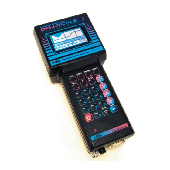
- Page 1 MSI9750A RF Remote Weight Indicator Operator’s Manual...
- Page 2 9750A HANDHELD RF REMOTE INDICATOR for CALE ® Page 2 MSI-9750A RF Remote Indicator • User Guide...
-
Page 3: Table Of Contents
MEASUREMENT SYSTEMS INTERNATIONAL TABLE OF CONTENTS 1 – I & O ........4 8 – S ............49 ECTION NTRODUCTION RIENTATION ECTION OINTS Introduction .................4 Introduction ...............49 9750A Keyboard ..............4 Set Point Setup Menu ............50 Key Descriptions ..............5 Program Set Point Menu ...........51 9750A Display Symbols ............6 9750A Response Menu .............52 General Information ............7... -
Page 4: Section 1 - Introduction & Orientation
9750A HANDHELD RF REMOTE INDICATOR for CALE SECTION 1 – INTRODUCTION & ORIENTATION INTRODUCTION The Measurement Systems International MSI-9750A RF Remote Indicator is an accessory component of MSI's ® CellScale System. Combined with 1 or more CellScales, the 9750A provides complete control over all scale and ®... -
Page 5: Key Descriptions
MEASUREMENT SYSTEMS INTERNATIONAL KEY DESCRIPTIONS POWER key turns the 9750A On and Off. The key must be held for 1 second to ensure startup. POWER POWER ZERO key is used to zero out residual weight on the scale. When entering numbers or strings the key is used ZERO ZERO... -
Page 6: 9750A Display Symbols
9750A HANDHELD RF REMOTE INDICATOR for CALE 9750A DISPLAY SYMBOLS The 9750A uses a full dot matrix graphics display which allows 3 sizes of fonts and full use of graphic symbols. On standard single channel and multi-channel displays, certain symbols are used for scale specifi c indications. ®... -
Page 7: General Information
MEASUREMENT SYSTEMS INTERNATIONAL GENERAL INFORMATION The 9750A is a versatile indicator capable of displaying many data items. As a member of the CellScale family the 9750A does not stand alone. It is a slave device to a MSI-9000 CellScale. All data displayed on the 9750A is received via RF from a master CellScale. -
Page 8: Features
9750A HANDHELD RF REMOTE INDICATOR for CALE FEATURES • Designed to meet or exceed all US and international standards. • • Multiple Customized Display Modes, single channel or multiple channel modes Multiple Customized Display Modes, single channel or multiple channel modes ®... -
Page 9: The Cellscale Family
MEASUREMENT SYSTEMS INTERNATIONAL THE CELLSCALE FAMILY 1) Model 9000 CellScale – Rugged unit for interfacing any scale and converting it to RF networking. 2) Model 9008 Multiplexer – Allows up to eight scales with independent calibrations, to share a single CellScale input channel. -
Page 10: Unit Setup
9750A HANDHELD RF REMOTE INDICATOR for CALE UNIT SETUP The 9750A is simple to setup and use. If there are no peripheral devices such as a printer or bar code scanner, setup consists of charging the battery, and setting the modem controls to talk to a 9000 CellScale. ®... -
Page 11: Section 2 - R Fscale Communications
MEASUREMENT SYSTEMS INTERNATIONAL SECTION 2 – RF SCALE COMMUNICATIONS The 9750A is a component of the MSI CellScale System. The CellScale system uses frequency hopping spread-spectrum RF Modem technology transmitting in the 2.4 GHz ISM band. RF Modems have been problematic as the RF bands are very hostile, corrupted by noise, path loss and inter- fering transmission from other radios. -
Page 12: Rf Network Setup
9750A HANDHELD RF REMOTE INDICATOR for CALE RF NETWORK SETUP The 9750A is a RF Modem connected device. The RF Modem requires setup to connect to one or more CellScales. The 9750A stores information for all 64 possible networks. Each network setting can be modifi ed with the “Modem Settings Menu”. -
Page 13: Advanced Modem Settings
MEASUREMENT SYSTEMS INTERNATIONAL ADVANCED MODEM SETTINGS The “ADVANCED SETTINGS’ menu provides access to some of the advanced features of the 9750A’s RF Modem. These features are not usually needed and should be left to defaults. ADVANCED SETTINGS LOCK OUT KEY 1 Lock Out Key Ø... -
Page 14: Configuring For Multiple Networks
9750A HANDHELD RF REMOTE INDICATOR for CALE CONFIGURING FOR MULTIPLE NETWORKS The 9750A can access multiple CellScales by switching Networks. A press of the key will change the ADDRESS network allowing the 9750A to monitor and control different scales. Because each CellScale has both a network and a CS address, these must be set up with the “SETUP RF NETWORK”... -
Page 15: Troubleshooting Rf Connection Problems
MEASUREMENT SYSTEMS INTERNATIONAL Transmit power set to HI. Time out set to 10 seconds. My Address remains unchanged and is the same in any network. TROUBLESHOOTING RF CONNECTION PROBLEMS Most connection problems are caused by improperly set up RF Networks. Both the 9750A and the master CellScale unit must have identical Network numbers. -
Page 16: Rf Site Testing
9750A HANDHELD RF REMOTE INDICATOR for CALE RF SITE TESTING The 9750A provides a means to check the effi ciency of RF transmissions using the RF Site Testing function. Program a function key (use the procedure in Section 4) to “RF Site Testing” to run the test. ®... -
Page 17: Section 3 - Scale Operation
MEASUREMENT SYSTEMS INTERNATIONAL SECTION 3 – SCALE OPERATION POWER To Turn On the Power 1) Press and hold for 1 second. The display should light and show the MSI POWER POWER Logo. If the system fails 2) The LCD then displays “MSI-9750A-5”, the Network currently loaded as the active to connect in 8 seconds or Address, and the software version number. -
Page 18: To Select The Display Channel
9750A HANDHELD RF REMOTE INDICATOR for CALE TO SELECT THE DISPLAY CHANNEL As mentioned above, the 9750A will access any channels setup in the CellScale. It does this with the “CHAN- NEL” function. Use the key to step from channel to channel as dictated by the Scan list stored in the CHANNEL CellScale. -
Page 19: Zero
MEASUREMENT SYSTEMS INTERNATIONAL To Switch Between Multi-Channel Display and Single Channel Displays 1) Highlight the channel you wish to see in the single channel mode by pressing the UP (^) or DOWN (v) cursor keys. 2) Once highlighted press DISPLAY. The highlighted channel will appear in the single channel mode. 3) Perform any scale function while in the single channel mode. -
Page 20: Tare
9750A HANDHELD RF REMOTE INDICATOR for CALE the scale will zero. The scale will accept a zero setting over the full Range of the scale (NTEP and other Legal-for-trade models may have a limited zero range). Zero settings above 4% of full scale will subtract from the overall capacity of the scale. For example if you zero out 100 lb. -
Page 21: Setup Tare Menu
MEASUREMENT SYSTEMS INTERNATIONAL Multiple Tare Memories The 9750A is capable of storing Tare values through the use of the ID Codes. Each ID code stores an independent Tare. See Section 3 “ID Codes” for more information. SETUP TARE MENU Programs the automatic TARE Clear function (Auto Clear), and the various Tare Modes including a means to disable Tare. -
Page 22: Units
9750A HANDHELD RF REMOTE INDICATOR for CALE UNITS Allows easy weight units conversions. Up to 8 Units are available. See “SETUP UNITS” in the CellScale Manual for details on activating the available units. Since Units are stored with each ID Code, the menu item for chang- ing units is found in the “Product ID Codes”... -
Page 23: Section 4 - Function Keys
MEASUREMENT SYSTEMS INTERNATIONAL SECTION 4 – FUNCTION KEYS SETUP FUNCTION KEYS The 9750A has six FUNCTION keys that can be programmed to any of several functions. The default func- tions are: TOTAL, CHANNEL, SEND/PRINT, ADDRESS, VIEW TOTAL, and ID. These default functions are printed on the front panel. -
Page 24: Default Function Keys
9750A HANDHELD RF REMOTE INDICATOR for CALE DEFAULT FUNCTION KEYS ....Default for F1. Add the current weight to the total, or Auto Total On/Off. Add to Total ......Default for F2. When pressed, changes to the next channel in the Scan Index. Switch Channel between selected scale channels. - Page 25 MEASUREMENT SYSTEMS INTERNATIONAL it’s Host3 print string..Tells the CellScale to output it’s Host1 print string. Send to CS Host 4 ..Outputs Comm 1 print string to the DE-9 connector, and tells the CellScale to output Print & Send Host 4 it’s Host4 print string.
-
Page 26: Custom Function Key Labels
9750A HANDHELD RF REMOTE INDICATOR for CALE Quick View of Function Keys The 9750A provides a quick way to view the assigned function keys. FUNCTION KEYS ARE 1) From any Weight Display press twice. ENTER ® F1 Total Channel F2 The current assigned function are displayed F3 Send Address F4... -
Page 27: Section 5 - I Dcodes
MEASUREMENT SYSTEMS INTERNATIONAL SECTION 5 – ID CODES • The CellScale can store 32 ID codes. The 9750A controls which ID Code is in use. • Each ID Code stores a Tare Value, a Total Value, a weighment counter, display mode (Net, Gross, Peak, etc...), Unit (lb., kg, ton, etc.), and two 20 byte ID code strings. -
Page 28: Setup Id Codes Menu
9750A HANDHELD RF REMOTE INDICATOR for CALE SETUP ID CODES MENU Allows setup of ID Codes. A new ID can be created, the 8 character ID Name can be edited, two 20 character print strings can be assigned to each ID Code. Also any or all IDs can be deleted from this menu. ®... -
Page 29: Using Id Codes
MEASUREMENT SYSTEMS INTERNATIONAL USING ID CODES To Create a New ID Code (Short method) This procedure assumes the default for ENTER F6 has not been modified by the user. 1) Press ENTER, then [F6]. 2) Using the numeric keypad enter a name for the new ID Code. Use the key to select letters as ALPHA required. -
Page 30: Id Code String 1 & String 2
9750A HANDHELD RF REMOTE INDICATOR for CALE The following procedure deletes all existing ID Codes and any totals and statistics stored in them. To Delete all ID Codes ® This procedure will delete all the product ID codes and all associated Names, Strings, Totals and Statistics for the current active channel. To delete all product IDs for all channels, you must select a channel using the CHANNEL key, then repeat this procedure for each Channel. -
Page 31: Section 6 - Total / Statistics
MEASUREMENT SYSTEMS INTERNATIONAL SECTION 6 – TOTAL / STATISTICS TOTAL • The 9750A can add independent weighments together and keep a counter of how many weighments were added (Totaled). The Weighments counter can be thought of as a box or palette counter. •... -
Page 32: Setup Total Menu
9750A HANDHELD RF REMOTE INDICATOR for CALE Auto Total Operation 1) Enable the desired Auto Total mode in the “SETUP TOTAL” menu (see “SETUP TOTAL”). Select the “AUTONORM”, “AUTOLOAD”, or the “AUTOPEAK” mode. Exit from the setup menu. 2) Use the key to disable (“TTL OFF”) or enable (“TTL ON”) Auto Total. -
Page 33: View Total
MEASUREMENT SYSTEMS INTERNATIONAL To Set the Total Mode The following example assumes the F1 function key is in its default mode of “TOTAL”. 1) Press SETUP. 2) Press the switch or select Total. TOTAL [F1] 3) The current Total Mode is shown on selection 1. 4) Press the key to bring up the “Total Mode Selection”... -
Page 34: Statistics
9750A HANDHELD RF REMOTE INDICATOR for CALE To Clear the Total Value (Current ID Code only) At any time during the following procedure the EXIT key cancels the Clear operation. Clears ID’s statistics registers as well. 1) Press ∑. The current total is displayed. VIEW 2) Press CLR. - Page 35 MEASUREMENT SYSTEMS INTERNATIONAL View Statistics and Grand Statistics The View Statistics feature uses totaled data from the current ID code in the CellScale to compute statistics. Grand Statistics uses totaled data from all ID codes. Only weight that has been totaled will be used in computing statistics.
-
Page 36: 9750A Setup
9750A HANDHELD RF REMOTE INDICATOR for CALE SECTION 7 – 9750A SETUP SYSTEM SETUP MENU SETUP SELECT MENU SYSTEM SETTINGS KEYPRESS VOLUME = KEYPRESS VOLUME = SETUP SELECT MENU SYSTEM SETTINGS ® 1 Function Keys CS SW Version: 2-24 2 Set Points 1 Key Volume is SETUP 3 nz... -
Page 37: Password Locks
MEASUREMENT SYSTEMS INTERNATIONAL Date Mode – Pressing changes the date mode from MM/DD/YY to DD-MM-YY. Time Mode – Press to change between 24 hour time or 12 hour time with AM/PM indication. Daylite (sic) Saving – Press to select the Daylight Saving mode. Select “ON” when in Daylight Savings Time (adds 1 hour). -
Page 38: Keyboard Lock
9750A HANDHELD RF REMOTE INDICATOR for CALE RESET ALL: The following procedure will cause you to lose all setups and will return the 9750A to it’s default settings. Use this procedure only as the last resort of having lost your password. ®... - Page 39 MEASUREMENT SYSTEMS INTERNATIONAL xS or xSL .... xS or xSL .... xS or xSL The Scan List Index position as stored in the CellScale where x is 1-8. Used on multiple display presets to show which scan list position is included on the preset display. These can be later altered to any scan list position 1-32.
-
Page 40: Display Setup Menu
9750A HANDHELD RF REMOTE INDICATOR for CALE Multi-Channel Preset Displays Multi-channel presets use the scan list position to assign channels to specifi c locations. After selecting the preset multi-channel display, the user can reassign any channel in the scan list to any screen location. The Multi-Channel Preset Displays are described by line numbers 1-8 corresponding to the small font layout. -
Page 41: Scale Display Setup Menu - Preset Displays
MEASUREMENT SYSTEMS INTERNATIONAL SCALE DISPLAY SETUP MENU – PRESET DISPLAYS SCALE DISPLAY SETUP SCALE DISPLAY SETUP BACKLIGHT BACKLIGHT DISPLAY 1 Single Scale Mode 1 Off (max batt-life) SETUP Shortcut EXIT 2 Multi Scale Mode 2 On for 15 seconds 3 Backlight 2min 3 On for 30 seconds 4 Backlight Level... -
Page 42: Using Display Setup
9750A HANDHELD RF REMOTE INDICATOR for CALE 2 Multi Scale Mode – Accesses multi channel display presets and multi channel custom menus. The various display modes are described on the previous page. 3 Backlight – Controls the duration of the backlight. The duration resets every time a key is pressed. Setting for shorter times increases battery life. -
Page 43: Custom Display Setup
MEASUREMENT SYSTEMS INTERNATIONAL CUSTOM DISPLAY SETUP The 9750A weight display is fully customizable. Both the single channel and multi-channel displays can be customized. All available data types plus custom text can be located anywhere on the screen in any of three font sizes: 1) Large Font –... - Page 44 9750A HANDHELD RF REMOTE INDICATOR for CALE Screen Formatting The 9750A LCD Screen allows a wide variety of scale display screen setups. The illustrations here demonstrate some of the possibilities. The custom display setup menus control the type and placement of available data types. The LCD is a graphics type organized in rows and columns.
- Page 45 MEASUREMENT SYSTEMS INTERNATIONAL Line Preview The bottom two lines of the Row Setup menu illustrate what the line has programmed into it. Data is displayed in row pairs. For example, while programming row 6, row 5 and 6 will be illustrated. When data from another line is present, as it will be with the large font, the preview area will show as lines.
-
Page 46: Custom Screen Setup Procedure
9750A HANDHELD RF REMOTE INDICATOR for CALE Selecting Items for Display The custom display setup menus provide access to all the data the scale can provide. When an item is present on the display, it will have an arrow next to its selection number. The length of some data items are fi xed, but many have variable lengths. -
Page 47: Custom Single Channel Display Setup Menu
MEASUREMENT SYSTEMS INTERNATIONAL CUSTOM SINGLE CHANNEL DISPLAY SETUP MENU SCALE DISPLAY SETUP ROW X-X XX CHARACTERS SCALE DISPLAY SETUP ROW X-X XX CHARACTERS DISPLAY 1 Product ID SETUP Shortcut EXIT 1 Single Scale Mode 2 Net-Gross-Tare Wt 2 Multi Scale Mode 3 Channel Info 3 Backlight 2min... -
Page 48: Custom Multi-Channel Display Setup Menu
9750A HANDHELD RF REMOTE INDICATOR for CALE CUSTOM MULTI-CHANNEL DISPLAY SETUP MENU SCALE DISPLAY SETUP ROW X-X XX CHARACTER SCALE DISPLAY SETUP ROW X-X XX CHARACTER DISPLAY SETUP 1 Product ID Shortcut EXIT 1 Single Scale Mode 2 Net-Gross-Tare Wt 2 Multi Scale Mode 3 Channel Info ®... -
Page 49: Section 8 - Set Points
MEASUREMENT SYSTEMS INTERNATIONAL SECTION 8 – SET POINTS INTRODUCTION The CellScale system provides extensive Set Point capabilities. Up to 32 Set Points are available. The CellScale performs the A/D conversions and does limit checking for all the Set Points. The 9750A receives Set Point infor- mation from the CellScale and responds as programmed. -
Page 50: Set Point Setup Menu
9750A HANDHELD RF REMOTE INDICATOR for CALE SET POINT SETUP MENU There are three ways to program values, operators, and remote relays for Set Points. 1) Use the Terminal Interface Mode at the CellScale, 2) use a 3750CS, or 3) use the 9750A. To Enter the Set Point Setup Menus ®... -
Page 51: Program Set Point Menu
MEASUREMENT SYSTEMS INTERNATIONAL PROGRAM SET POINT MENU 1 SP XX -SPName- To edit Set Point To edit Set Point 2 9750 Response See General Text Editing Name 3 Input Source ALPHA Procedure 4 Output Assign 5 Delay XXXXXms 0 F4 Menu 6 Latch 8 ENT Save... -
Page 52: 9750A Response Menu
9750A HANDHELD RF REMOTE INDICATOR for CALE 9750A RESPONSE MENU The 9750A responds to set points in three ways: with an audible alarm, a message display, or a message sent to comm port 1. These menus program this response. ® SET POINT SET POINT XX 1 Audible Alarms... -
Page 53: Set Point Formula Menu
MEASUREMENT SYSTEMS INTERNATIONAL SET POINT FORMULA MENU FORMULA OPERATOR 1 FORMULA SP XX OPERATOR 1 SP XX 1 Operator 1 > 2 Value 1 XXXXXXX 1 Greater Than > 3 Val 1 Type GROSS 2 > or Equal >= 4 Dual Value 3 Less Than <... -
Page 54: Section 9 - Communication Ports
9750A HANDHELD RF REMOTE INDICATOR for CALE SECTION 9 – COMMUNICATION PORTS INTRODUCTION • • The MSI 9750A is equipped with a single RS-232 serial input / output. The Comm Port is intended for inter- The MSI 9750A is equipped with a single RS-232 serial input / output. The Comm Port is intended for inter- ®... -
Page 55: Comm Port Setup Menu
MEASUREMENT SYSTEMS INTERNATIONAL the weight is in motion and/or not stable. 3) Print on CTS (Clear to Send, a RS-232 handshake line) – By toggling the CTS line from space to mark, the print string will be transmitted. If an interval is set, the string will continue to print as long as CTS is asserted. “Motion Check”... - Page 56 9750A HANDHELD RF REMOTE INDICATOR for CALE SEND/PRINT SETUP SELECT MENU COMM PORT 2 SETUP SELECT MENU COMM PORT 2 1 Function Keys SETUP SELECT MENU SETUP SELECT MENU Shortcut 2 Set Points 1 Enter/Edit Strings 1 Channel & Calibrate SETUP 3 System 2 Output Interval...
-
Page 57: General Text Entry
MEASUREMENT SYSTEMS INTERNATIONAL 5) MODE: The MODE menu sets the communications mode for the port. Use “TALK” for outputting data to a printer that uses hardware handshaking or no handshaking. Use “DUPLEX” for printers with software hand- shaking (XON / XOFF, etc.) or to talk and listen to a computer. Use “LISTEN” to only receive commands from a computer. -
Page 58: General Text Entry Menu
9750A HANDHELD RF REMOTE INDICATOR for CALE GENERAL TEXT ENTRY MENU ASCII CHARACTERS PUNCTUATION MENU ASCII CHARACTERS PUNCTUATION MENU 1 Punctuation 2 Printable Symbols ADDRESS ® 3 Control Characters 0 F4 Menu 4 Enter Decimal Char ‘ 512 ENT Save 5 Full Screen 9 “... -
Page 59: Printer / Output Formatting
MEASUREMENT SYSTEMS INTERNATIONAL Alternate Characters, Punctuation, Symbols, and Control Characters 1) While in the text entry screen, press the key. This enables the ASCII Characters Menu. This menu [F4] provides links to special characters. 2) For standard punctuation, press [1]. For other printable characters, press [2]. For ASCII control characters, press [3]. -
Page 60: Programming The End Of Line Or Start Of Line Strings
9750A HANDHELD RF REMOTE INDICATOR for CALE 6) @W3 causes the current Net weight to be printed. If the scale was in the NET mode, @W1 would have worked as well. 7) @D6 causes the current date to be printed in MM/DD/YYYY format 8) @E causes the end-of-line string to be sent (CR/LF). -
Page 61: Serial Output "@" Commands
MEASUREMENT SYSTEMS INTERNATIONAL SERIAL OUTPUT “@” COMMANDS The printer formatting “@” commands and their data confi gurations are as follows: Description Command Suffi x Input Output examples & comments examples *= a space or place holder Reset the host parser None This command can be used at any time to reset the command parser... - Page 62 9750A HANDHELD RF REMOTE INDICATOR for CALE Description Command Suffi x Input Output examples & comments examples *= a space or place holder Print Modem ID xxx where x is the modem ID from 1-254 ® Output ID String 1=ID String 1 String 1 from the current ID.
- Page 63 MEASUREMENT SYSTEMS INTERNATIONAL Description Command Suffi x Input Output examples & comments examples *= a space or place holder Output Weight Value and mode @W 1=current weight **20.002*LB***GROSS* Length: 20, fi xed. Leading zeros suppressed 2=gross **205.08*KG***GROSS* Length: 20, fi xed. Leading zeros suppressed 3=net *1188.50*G****NET*** Length: 20, fi...
-
Page 64: Section 10 - Data Logging
9750A HANDHELD RF REMOTE INDICATOR for CALE SECTION 10 – DATA LOGGING INTRODUCTION The 9750A has two battery backed memory locations for storing scale data. Predefi ned function keys are available The 9750A has two battery backed memory locations for storing scale data. Predefi ned function keys are available ®... -
Page 65: Data Logging Control Menu
MEASUREMENT SYSTEMS INTERNATIONAL DATA LOGGING CONTROL MENU The Data Logging Control Menu provides a means to upload stored data, and erase the data logging memory locations. The Data Logging Control Menu is reached by pressing followed by NET/GROSS. Alternately the SETUP menu can be reached through the Comm Port and Strings Menu. -
Page 66: Section 11 - Text Messaging
9750A HANDHELD RF REMOTE INDICATOR for CALE SECTION 11 – TEXT MESSAGING The MSI-9750A provides a means for sending messages from host computers directly to the 9750A display. The remote computer uses a host command to send data to any 9750A on the same network (0-31). Once the 9750A receives a text message, it is displayed until a key is pressed. -
Page 67: 9750A To Host Messages
MEASUREMENT SYSTEMS INTERNATIONAL 9750A TO HOST MESSAGES Once a sent message is observed by the 9750A user, pushing any key will clear the message and return the 9750A to the last display mode. An acknowledgment string is automatically sent back to the modem that generated the message. - Page 68 9750A HANDHELD RF REMOTE INDICATOR for CALE ® Page 68 MSI-9750A RF Remote Indicator • User Guide...
-
Page 69: Section 12 - Bar Code
MEASUREMENT SYSTEMS INTERNATIONAL SECTION 12 – BAR CODE The Bar Code features of the 9750A allow the user to add scanned data to weight readings and trigger transmis- sions directly into RF connected computers. In combination with the Data Logging features, bar code scans can trigger data storage for uploading later. - Page 70 9750A HANDHELD RF REMOTE INDICATOR for CALE BAR CODE SETUP MENU SETUP SELECT MENU SETUP SELECT MENU BAR CODE SETUP MENU 1 Function Keys 1 Bar Code 1 Buffer 2 Set Points 2 Bar Code 2 Buffer SETUP 3 System 3 Bar Code 3 Buffer 4 Password Locks...
-
Page 71: Section 13 - Channel Setup & Calibration
MEASUREMENT SYSTEMS INTERNATIONAL SECTION 13 – CHANNEL SETUP & CALIBRATION CHANNEL SETUP MENU CHANNEL / CALIBRATION CHANNEL / CALIBRATION 1 Channel is ACTIVE --Channel Name-- --Channel Name-- --Chn-- --Chn-- --Index-- --Index-- CHANNEL SETUP 1 Channel INACTIVE Shortcut 1 Channel is ACTIVE 2 Filter 3 Calibrate Settings... -
Page 72: Calibrate General Information
9750A HANDHELD RF REMOTE INDICATOR for CALE CALIBRATE GENERAL INFORMATION The following sections are intended for qualifi ed scale technicians. The CellScale can be calibrated either directly using the Terminal Interface mode, or by using a 9750A or 3750CS. See the CellScale operators guide for informa- tion on direct calibration. - Page 73 MEASUREMENT SYSTEMS INTERNATIONAL CHANNEL / CALIBRATION ENTER to CHANNEL / CALIBRATION --Channel Name-- --Channel Name-- Recalibrate --Chn-- --Chn-- --Index-- --Index-- CHANNEL SETUP Shortcut 1 Channel is ACTIVE CLR to Reset Cal 2 Filter 3 Calibrate Settings ESC to Exit Cal 4 Start Calibration 5 Zero RUSure Msg ON ZERO...
-
Page 74: To Enable / Disable Azm (Auto Zero Maintenance)
9750A HANDHELD RF REMOTE INDICATOR for CALE TO ENABLE / DISABLE AZM (AUTO ZERO MAINTENANCE) AZM is used to adjust out variations at zero caused by debris or water on the scale, temperature drift, and any other minor variation that affects the zero setting. Typically AZM is set to 0.5d or 1d, which is adequate for most modern scale systems. -
Page 75: Center-Of-Zero (Coz) Indicator
MEASUREMENT SYSTEMS INTERNATIONAL CENTER-OF-ZERO (COZ) INDICATOR The COZ indicator turns on when the scale is within 1/4 d of the last zero setting. Some legal-for-trade jurisdic- tions require its use. To Enable/Disable the COZ Indicator Before starting the following procedure, you must be in the Top Menu Level of Calibration. 1) Press SETUP, then CHANNEL. -
Page 76: Installing Firmware Updates
9750A HANDHELD RF REMOTE INDICATOR for CALE INSTALLING FIRMWARE UPDATES The 9750A contains Flash memory that allows the fi rmware to be upgraded through the Comm Port. A “Boot Loader” program is used to load a new program fi le into the 95750. MSI will update and improve the 9750A feature set over time and provide program updates free of charge. - Page 77 MEASUREMENT SYSTEMS INTERNATIONAL _+)#!!!_+)#!!!_+)#!!!_+)#!!!_+)#!!!_+)#!!!_+)#!!!_+)#!!!_ #!!!_+)#!!!_+)#!!!_+)#!!!_+)#!!!_+)#!!!_+)#!!!_+)#!!!_+)# before matching baud rates after matching baud When you can read this, press any key. rates When you can read this, press any key. When you can read this, press any key. MSI Boot Loader Version 3.K3 Update Application Change Baud Rate (ESC)
-
Page 78: 9750A Setup Duplicating
9750A HANDHELD RF REMOTE INDICATOR for CALE MSI Boot Loader Version 3.K3 Update Application ® Change Baud Rate (ESC) Start Application 12) After all sectors are programmed, press the key on the 9750A. The 9750A will turn off. Remove POWER the serial cable from the 9750A Comm Port. -
Page 79: Appendixa - Menu Maps
MEASUREMENT SYSTEMS INTERNATIONAL APPENDIX A – MENU MAPS SETUP SELECT MENU SETUP SELECT MENU SETUP SELECT MENU SETUP SELECT MENU SETUP SELECT MENU 1 Function Keys 1 Channel & Calibrate 2 Set Points 2 Display SETUP 3 System 3 RF Modem 4 Password Locks 4 Comm 2 &... -
Page 80: Function Keys
9750A HANDHELD RF REMOTE INDICATOR for CALE FUNCTION KEYS SETUP SELECT MENU FUNCTION KEY ASSIGNS ENTER-FKEY ASSIGNS ENTER-FKEY ASSIGNS SETUP SELECT MENU FUNCTION KEY ASSIGNS 1 Function Keys 1 F1 is Add to Total 1 E1 is Clr Last ∑ 2 Set Points 2 F2 is Next Channel 2 E2 is Back Channel... -
Page 81: Serial & Strings
MEASUREMENT SYSTEMS INTERNATIONAL SERIAL & STRINGS SEND/PRINT SETUP SELECT MENU COMM PORT 2 SETUP SELECT MENU COMM PORT 2 1 Function Keys SETUP SELECT MENU SETUP SELECT MENU Shortcut 2 Set Points 1 Enter/Edit Strings 1 Channel & Calibrate SETUP 3 System 2 Output Interval 2 Display... -
Page 82: Product Id Codes
9750A HANDHELD RF REMOTE INDICATOR for CALE PRODUCT ID CODES SETUP SELECT MENU SETUP SELECT MENU PRODUCT ID Chan SETUP SELECT MENU SETUP SELECT MENU PRODUCT ID Chan X-X 1 Function Keys 1 Channel & Calibrate Net XX IDName-- ® 2 Set Points 2 Scale Display Line 1 New Product ID... -
Page 83: Tare Settings
MEASUREMENT SYSTEMS INTERNATIONAL TARE SETTINGS TARE SETTINGS TARE SETTINGS -CHANNEL NAME or NUM- TARE TARE SETUP Shortcut 1 Disable Auto Clear 2 Set Clear on Minus 3 Set Clear on Total 4 Tare by Product ID 5 Same Tare All ID’s RF MODEM SETTINGS MODEM SETTINGS v2.05... -
Page 84: Scale Display Setup
9750A HANDHELD RF REMOTE INDICATOR for CALE SCALE DISPLAY SETUP BACKLIGHT BACKLIGHT SCALE DISPLAY SETUP SCALE DISPLAY SETUP DISPLAY 1 Single Scale Mode 1 Off (max batt-life) SETUP Shortcut EXIT 2 Multi Scale Mode 2 On for 15 seconds ® 3 Backlight 2min 3 On for 30 seconds... -
Page 85: Scale Single Channel Custom Display Setup
MEASUREMENT SYSTEMS INTERNATIONAL SCALE SINGLE CHANNEL CUSTOM DISPLAY SETUP SCALE DISPLAY SETUP ROW X-X XX CHARACTERS SCALE DISPLAY SETUP ROW X-X XX CHARACTERS DISPLAY 1 Product ID SETUP Shortcut EXIT 1 Single Scale Mode 2 Net-Gross-Tare Wt 2 Multi Scale Mode 3 Channel Info 3 Backlight 2min... -
Page 86: Scale Multi-Channel Custom Display Setup
9750A HANDHELD RF REMOTE INDICATOR for CALE SCALE MULTI-CHANNEL CUSTOM DISPLAY SETUP SCALE DISPLAY SETUP ROW X-X XX CHARACTER SCALE DISPLAY SETUP ROW X-X XX CHARACTER DISPLAY SETUP 1 Product ID Shortcut EXIT 1 Single Scale Mode 2 Net-Gross-Tare Wt 2 Multi Scale Mode 3 Channel Info ®... -
Page 87: Channel / Calibrate Settings
MEASUREMENT SYSTEMS INTERNATIONAL CHANNEL / CALIBRATE SETTINGS 1 Channel is ACTIVE CHANNEL / CALIBRATION CHANNEL / CALIBRATION --Channel Name-- --Channel Name-- --Chn-- --Index-- --Chn-- --Index-- CHANNEL SETUP 1 Channel INACTIVE Shortcut 1 Channel is ACTIVE 2 Filter 3 Calibrate Settings CHANNEL FILTER CHANNEL FILTER 4 Start Calibration... -
Page 88: System Settings
9750A HANDHELD RF REMOTE INDICATOR for CALE SYSTEM SETTINGS SETUP SELECT MENU SYSTEM SETTINGS KEYPRESS VOLUME = KEYPRESS VOLUME = SETUP SELECT MENU SYSTEM SETTINGS 1 Function Keys CS SW Version: 2-24 1 Key Volume is 2 Set Points SETUP 3 nz 3 System 2 Alarm Volume is... -
Page 89: Calibration
MEASUREMENT SYSTEMS INTERNATIONAL CALIBRATION CHANNEL / CALIBRATION ENTER to CHANNEL / CALIBRATION --Channel Name-- --Channel Name-- Recalibrate --Chn-- --Chn-- --Index-- --Index-- CHANNEL SETUP Shortcut 1 Channel is ACTIVE CLR to Reset Cal 2 Filter 3 Calibrate Settings ESC to Exit Cal 4 Start Calibration 5 Zero RUSure Msg ON ZERO... -
Page 90: General Text Entry
9750A HANDHELD RF REMOTE INDICATOR for CALE GENERAL TEXT ENTRY ASCII CHARACTERS PUNCTUATION MENU ASCII CHARACTERS PUNCTUATION MENU 1 Punctuation 2 Printable Symbols ADDRESS 3 Control Characters ® 0 F4 Menu 4 Enter Decimal Char ‘ 512 ENT Save 5 Full Screen 9 “... -
Page 91: Set Points
MEASUREMENT SYSTEMS INTERNATIONAL SET POINTS Input Set Point MASTER SET POINTS PROGRAM SET POINT MASTER SET POINTS PROGRAM SET POINT 1 SP XX -SPName- # for programming ESC exits no change 2 9750 Response (1-32) 1 Program Set Point ENTER edits value 3 Input Source ENTER SETUP... -
Page 92: Appendixb - Ascii C
9750A HANDHELD RF REMOTE INDICATOR for CALE APPENDIX B – ASCII CHART ® Page 92 MSI-9750A RF Remote Indicator • User Guide... - Page 93 MEASUREMENT SYSTEMS INTERNATIONAL APPENDIX C – SPECIFICATIONS & SUMMARY OF FEATURES Temperature Range Display • 64 x 128 Full Graphics Module • -20° C to +60° C Operating (-4° F to 140° F) • Multiple Font sizes, up to 8 lines of 21 characters •...
-
Page 94: The Msi Limited Warranty
THE MSI LIMITED WARRANTY MEASUREMENT SYSTEMS INTERNATIONAL, INC., WARRANTS load sensing elements and meters against defects in workmanship and materials for a period of one year from date of purchase and warrants electrical cables and batteries against the same defects for a period of ninety (90) days from date of purchase. Any device which proves defective during the warranty period will be replaced or repaired at no charge;... - Page 95 Measurement Systems International A RICE LAKE WEIGHING SYSTEMS COMPANY 14240 Interurban Avenue South Suite 200 Seattle, WA 98168-4661 Phone: 206-433-0199 Fax: 206-244-8470 www.msiscales.com © 2012 Rice Lake Weighing Systems...
Need help?
Do you have a question about the Measurement Systems International MSI9750A and is the answer not in the manual?
Questions and answers