Table of Contents
Advertisement
Quick Links
Advertisement
Table of Contents

Subscribe to Our Youtube Channel
Related Manuals for Rice Lake MSI9000


Summary of Contents for Rice Lake MSI9000
- Page 1 MSI9000 Spread Spectrum RF Operator’s Manual...
-
Page 2: Table Of Contents
9000 CellScale ™ RF SCALE INSTRUMENTATION TABLE OF CONTENTS 1 – I & I ........3 Setting up the Scan List ..............46 ECTION NTRODUCTION NSTALLATION Installation ..................3 Activate, Inactivate Channels .............49 Firmware Version Notice ..............3 CellScale Throughput Considerations ........49 CellScale Connectors Diagram .............4 Slave CellScale - Channel 5 Setup ..........51 Power and Remote Switches Cable ..........4 Setting up the Math Channels .............51... -
Page 3: Section 1 - Introduction & Installation
If there are no peripheral devices such as a printer or scoreboard, setup consists of installing the unit in its per- manent location (see installation templates), plugging in the Antenna and load sensors, and applying power. Power–MSI9000 The CellScale is powered by any DC source from 9V to 30V or optionally with 85-265VAC. The universal AC... -
Page 4: Cellscale Connectors Diagram
9000 CellScale ™ RF SCALE INSTRUMENTATION CELLSCALE CONNECTORS Power and Remote Switches Cable Power is supplied through a pre assembled cable (MSI P/N 12020). It provides for DC power in (9-30Vdc), two switches, and a remote LED indicator. The switches and LED are supplied by the end user. Blue –... -
Page 5: Sensor Input Connector
MEASUREMENT SYSTEMS INTERNATIONAL Sensor Input The sensor input connector has twelve pins. A minimum scale connection consists of +Excitation, -Excitation, +Signal Ch1, and -Signal Ch1 (4 wire). The user can add +Sense and -Sense for a 6 wire connection to a sum- ming box or 6 wire connected load cell. - Page 6 9000 CellScale ™ RF SCALE INSTRUMENTATION to the Hi wire, and ground to the low wire to trigger the switch 2 function. This must be momentary! The func- tion is edge triggered. The Common must be low for the isolated input to function. If the Isolated input is not needed, the common can be high or low return.
-
Page 7: Comm Port Cables
MEASUREMENT SYSTEMS INTERNATIONAL 60Vdc Max Set Points Limit 500mA per output Negative Common CellScale Battery or Set Points Port Power Supply Pin 1- Iso Input Relay Power Pin 2 - K1 Source BLUE – Pin 3 - COM Pin 4 - K2 GREY Pin 5 - K3 Driving Lamps and Audible Alarm... -
Page 8: Wiring Diagrams
9000 CellScale ™ RF SCALE INSTRUMENTATION White – RTS/RTR output from CellScale. Connect to CTS input of DTE. Blue – Signal Ground Drain Wire – Connect to metal shell. RS-422/485 Operation RS-422 and RS-485 serial connections are used when long wire runs are necessary. The 485 spec covers cable runs up to 4000’. - Page 9 MEASUREMENT SYSTEMS INTERNATIONAL RS-485/422 Full Duplex Connection 485 Termination Resistor. 120Ω 1/4W Final receiver only. CellScale Remote Device Shield COMM PORT Pin 1- TD+ Pin 2 - TD- Up to 1000 meters BLUE Pin 3 - GND Pin 4 - RD+ GREY Pin 5 - RD- CHASSIS GND...
-
Page 10: Cellscale Block Diagram
9000 CellScale ™ RF SCALE INSTRUMENTATION CELLSCALE BLOCK DIAGRAM CellScale Input Channel 1 Spread 16 Bit 24 Bit A/D Spectrum Input Channel 2 Embedded Converter RF Modem µController Mux Control A 512k Flash Input Channel 3 24 Bit A/D 512k RAM Opto-isolated Converter Input Channel 4... -
Page 11: Cellscale Mounting Holes
MEASUREMENT SYSTEMS INTERNATIONAL CELLSCALE MOUNTING HOLES Enlarge this template by 200%. Rev 4 4/4/06 for SW Ver 5-xx, 2nd Generation Modems • MSI-9000 CellScale™ User Guide Page 11... - Page 12 9000 CellScale ™ RF SCALE INSTRUMENTATION • Page 12 MSI-9000 CellScale™ User Guide...
-
Page 13: Rf Scale Communications
MEASUREMENT SYSTEMS INTERNATIONAL SECTION 2 – RF SCALE COMMUNICATIONS – THE CELLSCALE SYSTEM INTRODUCTION The 9000 CellScale is the key component of the MSI CellScale System. The CellScale system uses frequency ™ hopping spread-spectrum RF Modem technology transmitting in the 2.4 GHz ISM band. RF Modems have been problematic as the RF bands are very hostile, corrupted by noise, path loss and inter- fering transmission from other radios. -
Page 14: Fcc Statement
9000 CellScale ™ RF SCALE INSTRUMENTATION numerous load sensors; send weighment data automatically from numerous load sensors to a computer database; cross reference shipments with inventory; track product flow; monitor shelf life; and unlimited others. ANTENNAS To meet FCC licensing rules, you must use only antennas supplied or recommended by MSI. MSI offers the CellScale with six antenna choices: 1) Standard Antenna –... -
Page 15: Standard Antenna
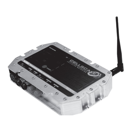
MEASUREMENT SYSTEMS INTERNATIONAL STANDARD ANTENNA The Standard Antenna (pictured here) is an articulated 1/2 wave 2dBi gain design with a standard TNC connector. This antenna and Coax connector, though resistant to water, is not water-proof. Seal the TNC base with an adhesive heat shrink boot if this antenna is exposed to rain. This Antenna should be vertically oriented. -
Page 16: Yagi, Corner Reflectors, Vehicle
9000 CellScale ™ RF SCALE INSTRUMENTATION YAGI ANTENNA A highly directional YAGI Antenna is available by special order. This antennas offers both high gain (14dBi) and controllable transmission pat- terns. This antenna must be carefully aligned for long distance applications. The Beamwidth of the Yagi is 30°... -
Page 17: Fcc's Mpe Requirements
MEASUREMENT SYSTEMS INTERNATIONAL STANDARD ANTENNA BULKHEAD EXTENSIONS MSI offers short Coaxial cable assemblies to extend the antenna connector when the CellScale equipment is mounted in an industrial enclosure. These Coaxial assemblies are designed for 2.4Ghz use and have TNC Male connectors at both ends. -
Page 18: Section 3 - Terminal Access Mode
9000 CellScale ™ RF SCALE INSTRUMENTATION SECTION 3 – TERMINAL ACCESS MODE One way to setup, control, calibrate, and receive data from a CellScale is using a terminal program through Comm Port 1. Tested terminal programs that function well with the CellScale include ProComm Plus, Qmodem, HyperTerm (shipped with many versions of Windows), WinTerm, and ZTerm or Microphone (for Macintosh). -
Page 19: Main Cellscale Menu
MEASUREMENT SYSTEMS INTERNATIONAL Main CellScale Menu ---------- MSI 9000 CellScale ---------- - (c) 2006 Measurement Systems International - ---------------------------------------------- 13:48:06 03/25/06 Channels/Calibration Communications Display Feature Locks/Passwords Product IDs Set Points System About... Enter choice : 1) Channels/Calibration – Calibration, channel setup, measurement parameters. 2) Communications –... -
Page 20: Cal Data Backup
9000 CellScale ™ RF SCALE INSTRUMENTATION removed from the data. 7) Tare – Setup tare options such as Auto clear, universal tare mode, and set tare for every ID programmed for the set channel. 8) Total – Setup total modes and total thresholds. 9) Units Lock –... - Page 21 MEASUREMENT SYSTEMS INTERNATIONAL Main CellScale Menu ➔ (1) Channels/Calibration ➔ (4) Channel scanlist functions ***** Channel ScanList ***** Add a specific channel-subchannel Delete a scanList entry Edit a scanList entry Move a scanList entry (ESC) Exit ----------------------------------------- Position = ch-subch, * indicates channel is active 1 = 1-1 9 = --- 17 = ---...
-
Page 22: Total
9000 CellScale ™ RF SCALE INSTRUMENTATION 1) Input channel and sub channel for this tare parameter setup. 2) Auto clear: Enabling “Auto Clear” causes the CellScale to clear the Tare Value after each lift greater than 0 NET. The Tare Value is cleared and the display mode reverts to Gross Weight once the load is removed (the weight goes below 0 NET). -
Page 23: Units Lock
MEASUREMENT SYSTEMS INTERNATIONAL Manual – Requires the operator pushes a button to total the current load. This button can be a pro- grammed external switch on the CellScale, the Total F key on any 3750CS, or the external cabled total switch found in the External Total Switch option. -
Page 24: Zero Mode Setup
9000 CellScale ™ RF SCALE INSTRUMENTATION Main CellScale Menu ➔ (1) Channels/Calibration ➔ (a) Zero ***** Zero setup ***** Choose the channel to change: Automatically zero at power up: Disabled AZM (auto zero maintenance): Enabled AZM range (0=1/2, 1-255): AZM time between checks: 1000 msec Current zero offset: Positive Zero range (+1 to +100%) -
Page 25: Define Terminal Keys
MEASUREMENT SYSTEMS INTERNATIONAL Main CellScale Menu ➔ (3) Display ➔ (2) Define a key function ***** Change a Display Key Menu Function ***** Menu key to configure is: 5, Undefined (ESC) Exit Type new value for menu key and hit (ENTER) 1) Zero 13) Tare;... -
Page 26: Feature Locks/Passwords Menu
9000 CellScale ™ RF SCALE INSTRUMENTATION parameters can easily be confirmed by assigning them to display locations. Us ‘p’ to see the second page of weight types. Main CellScale Menu ➔ (4) Feature Locks / Passwords ***** Feature Locks/Passwords Setup ***** Calibration Channel menu Communications... -
Page 27: Systems Menus/Real Time Clock
MEASUREMENT SYSTEMS INTERNATIONAL Main CellScale Menu ➔ (6) Set Points ***** Set Points ***** All set points are: Disabled Clear latch Setup overhead Setup outputs Setup values (ESC) Exit Set point status 1 = Disab 9 = Disab 17 = Disab 25 = Disab 2 = Disab 10 = Disab... -
Page 28: Led Management
9000 CellScale ™ RF SCALE INSTRUMENTATION Main CellScale Menu ➔ (7) System ➔ (2) Initializations ***** Initializations ***** Clear all calibration data to defaults Clear all product ID data to defaults Clear all registry data to defaults Clear all serial settings to defaults Clear all set point settings to defaults... -
Page 29: Systems Menus/Power Settings
MEASUREMENT SYSTEMS INTERNATIONAL Main CellScale Menu ➔ (7) System ➔ (4) Switch Functions ➔ (1) Switch #1 Functions ***** Choose Function of Switch #1 ***** Find Slaves Next ID Power Print Tare Total Total Clear Total View Units Zero Not Defined (ESC) Exit Current function of switch #1 is:... -
Page 30: Auto Power Up/Down
9000 CellScale ™ RF SCALE INSTRUMENTATION Type % battery that CellScale shuts down (1-100): 5) Shutdown With - This menu item allows the operator to select the power down parameters. The following sub-menu provides the choices: 1-Switch only. This is the SW1 or SW2 set up as power. 2- adds the key- board in the terminal interface program. -
Page 31: About (Cellscale) Screen
MEASUREMENT SYSTEMS INTERNATIONAL Press until the desired power source is shown. Adjust the input voltage to the asked for setting. Then press to calibrate the battery check digital comparator. Main CellScale Menu ➔ (8) About ***** About ***** Hardware built: 04/26/06 at 09:29:30 Serial number: 123454321... -
Page 32: Section 4 - Set U P Communications
9000 CellScale ™ RF SCALE INSTRUMENTATION SECTION 4 – SETTING UP COMMUNICATIONS COMMPORT 2 - RF MODEM The CellScale, being a networked RF device, requires proper setup of the communications parameters. As mentioned in the introduction, the CellScale uses a Star topology, with the CellScale as the Master device (in most situations). -
Page 33: Rf Configuration Procedure
MEASUREMENT SYSTEMS INTERNATIONAL The CellScale™ features a heavy duty, milled enclosure rated at NEMA 4 IP 65 or NEMA 6 IP 67 with the long range an Setting the RF Configuration 1) Connect a terminal to the CellScale. This can be a computer with virtually any terminal emulation soft- ware. - Page 34 9000 CellScale ™ RF SCALE INSTRUMENTATION 5) To change the Network number, push 2. The following menu appears. Enter network number (0 - 63): 6) Enter the desired Network number. For our example, type 12, then press return on the terminal keyboard. Now the Comm 2 Settings menu appears with the network changed to 12.
-
Page 35: Configure A Cellscale As A Slave
MEASUREMENT SYSTEMS INTERNATIONAL to determine the 802.11b band in use. Also found here is a setting that makes the 9000 French compliant. CommPort 2 Menu ➔ (c) Advanced Radio Setup ***** Advanced Radio Setup ***** Hop Duration: 10.0 mSec Max Number of Remotes: Bytes Per Slot: Retry Limit: Lockout Key:... -
Page 36: Comm Port Settings
9000 CellScale ™ RF SCALE INSTRUMENTATION All CellScale parameters are setup in the terminal mode. Once Comm Port 1 is switched to Host Mode, only the command ;MSI9MSI9 will return function to the Terminal mode. [Return] Menu in Terminal Mode ***** Comport 1 Settings ***** Function: Terminal... -
Page 37: Virtual Comm Ports 3, 4, And 5
MEASUREMENT SYSTEMS INTERNATIONAL ing on comm port speed. 2) DCE. 3) DTE. 4) CTS/RTR. See additional comments on these handshaking modes following. b) Control - The control choices are: 1) On command - the CellScale must receive a print command from either a host, or from a key programmed for “Print”. -
Page 38: Inputing Data Strings
9000 CellScale ™ RF SCALE INSTRUMENTATION Comm Port String: Up to 512 characters. Due to @ Codes the resultant output can actually be larger than 512 characters. Comm Port Start String: The “Start” string can be 0 to 64 characters long. It is intended for commonly used commands that usually precede printed lines. -
Page 39: Rf Registry
MEASUREMENT SYSTEMS INTERNATIONAL To Initialize a Print string 1) From the main menu, select “Communications” [2]. Then press “Data Strings” [6]. 2) Use the key to select the comm port. 3) Use the numbered key next to the string you wish to initialize. 4) When the edit screen appears, push the key. - Page 40 9000 CellScale ™ RF SCALE INSTRUMENTATION Main CellScale Menu ➔ (2) Communications ➔ (7) Registry ➔ (n) Show next... ***** Registry ***** Contact a smart device Configure a device Add a 9020 CellModem to Comm3 Add a 9020 CellModem to Comm4 Add a 9020 CellModem to Comm5 Contact smart device with serial number &...
-
Page 41: Remote Device Configuration
MEASUREMENT SYSTEMS INTERNATIONAL Main CellScale Menu ➔ (8) System ➔ (2) Registry ➔ (2) Configure a device ***** Configure Registry ***** Change current device from Change device name : 3750CS Meter1 Change broadcast rate msgs every 1 secs Change timeout : 30 seconds Change retry... -
Page 42: Legal-For-Trade Control Device
9000 CellScale ™ RF SCALE INSTRUMENTATION LEGAL FOR TRADE CONTROL DEVICE When the CellScale is configured for NTEP or OIML Legal-For-Trade (LFT) only one remote device is allowed to have control over the CellScale. The control device is the only RF connected device that can zero, tare, calibrate, and any other controls that are considered metrologically significant. - Page 43 MEASUREMENT SYSTEMS INTERNATIONAL Rev 4 4/4/06 for SW Ver 5-xx, 2nd Generation Modems • MSI-9000 CellScale™ User Guide Page 43...
-
Page 44: Section 5 - Channels , Scanlists , Id Codes
9000 CellScale ™ RF SCALE INSTRUMENTATION SECTION 5 – CHANNELS, SCANLISTS, AND PRODUCT ID CODES The CellScale’s multiple channel capability allows a single CellScale to monitor multiple inputs. The mecha- nism for this is the Scan List. The Scan List is merely a list of input channels, math channels, and or remote channels, that dictate the order in which the CellScale reads its inputs. -
Page 45: Id Codes Overview
MEASUREMENT SYSTEMS INTERNATIONAL CellScale. The name can be all numbers, all letters, or a combination of numerals and letters. Once the name is entered by the user, the CellScale scans its memory to see if the ID Code already exists. If it does, all new totaled weighments are added to the previously totaled weighments, and any preexisting Tare value will be used for NET weight computation. -
Page 46: Setting Up The Scan List
9000 CellScale ™ RF SCALE INSTRUMENTATION 2 (each 20 characters). These strings are used in identifying and printing setups. If a permanent tare is associated with the ID input the value and check the “NET” button. 8) If more ID Codes are needed for this input channel, input the information in the Product IDs section. Leave the Channel section blank. - Page 47 MEASUREMENT SYSTEMS INTERNATIONAL Valid primary channels are 1 - 2, Valid secondary channels are 3 - 4, (2nd A/D option required) Valid slave channel 5, (Slave CellScale required) Valid math channel Valid sub-channels are 1 - 8, Type channel#-subChannel# (Ex. 1-1): 2-1 Type the scanList position to place this (1 - 32):2 Position = ch-subch, * indicates channel is active...
- Page 48 9000 CellScale ™ RF SCALE INSTRUMENTATION ***** Edit a ScanList entry ***** ScanList entry: 01 = Channel 1-1 Channel 1-1 name: ....Channel type: Type A, 10,000 counts Hardware excitation: Hardware output rate: 57 Hz # readings per dwell: Active/in-active status: Active (ESC) Exit...
-
Page 49: Activate, Inactivate Channels
MEASUREMENT SYSTEMS INTERNATIONAL 10) If a channel name is needed add one by pressing [2]. Enter new name (up to 20 chars): 11) Type in a channel name. Limit the name to 20 characters or less. Note only the first 8 characters are dis- played on a 3750CS. - Page 50 9000 CellScale ™ RF SCALE INSTRUMENTATION SETTING UP SLAVE CELLSCALES AS CHANNEL 5 A CellScale configured as a network remote can supply data to another master CellScale via RF using chan- nel 5-1 through 5-8. Setup of this is straightforward. It is advised that the scan list on the remote CellScale is known and documented, and that all channels on the remote CellScale are already calibrated (calibration per- formed while in the Master mode or connected with a terminal directly to the Remote CellScale).
-
Page 51: Slave Cellscale - Channel 5 Setup
MEASUREMENT SYSTEMS INTERNATIONAL Valid primary channels are 1 - 2, Valid secondary channels are 3 - 4, (2nd A/D option required) Valid slave channel 5, (Slave CellScale required) Valid math channel Valid sub-channels are 1 - 8, Type channel#-subChannel# (Ex. 1-1): 5-1 Type the slave CellScale radio ID (1 - 254): 122 Position = ch-subch, * indicates channel is active... -
Page 52: Setting Up The Math Channels
9000 CellScale ™ RF SCALE INSTRUMENTATION Type the scanList position to place this (1 - 32): 2 Position = ch-subch, * indicates channel is active 1 = 1-1 9 = --- 17 = --- 25 = --- 2 = --- 10 = --- 18 = --- 26 = ---... - Page 53 MEASUREMENT SYSTEMS INTERNATIONAL r((1*1)+(2*2)) RMS (square root of the sum of the squares) of channel 1 and 2. It is possible to include a math channel in another math channels calculation. However, you must not allow a circular argument. Math Channel Entry Procedure 1) After setting up all the input channels in the scan list, add math channels in the same way as standard input channels except input 6-1 to 6-8 as the channel-subchannel number.
-
Page 54: Example Scan Lists
9000 CellScale ™ RF SCALE INSTRUMENTATION ***** Edit a Math Channel Expression ***** Enter expression by typing on keyboard Set expression to sum of all active channels Clear the expression (ESC) Exit Math channel 6-1 expression 0x20 7) Press to input the expression using the terminal keyboard. ***** Type a Math Channel Expression ***** (ESC) Exit... -
Page 55: Example Math Channels
MEASUREMENT SYSTEMS INTERNATIONAL 3= 1-3 Pad placed under rear left wheel 4= 1-4 Pad placed under rear right wheel 5= 6-1 Channel 6-1 defined as (CH1-1)+(CH1-2) (see Math Channels) 6= 6-2 Channel 6-2 defined as (CH1-3)+(CH1-4) 7= 6-3 Channel 6-3 defined as (CH1-1)+(CH1-2)+(CH1-3)+(CH1-4) This scan list could be used with a wheel weighing system. - Page 56 9000 CellScale ™ RF SCALE INSTRUMENTATION 1*k31.103 Converts grams (unit of sc1 must be grams) to troy ounces 1*k2240 Converts pounds (unit of sc1 must be pounds) to long tons (1/(1+2))*k10 Calculates center of gravity from two weights. Returns the distance from center of weight 1. Replace the ‘10’...
-
Page 57: Setup Product Id Codes
MEASUREMENT SYSTEMS INTERNATIONAL Math Channels are a versatile, powerful tool and open up many application possibilities. SETUP PRODUCT ID CODES Main CellScale Menu ➔ (5) Product IDs ***** Product Data ***** Show the next Show the previous Find/Create an Show statistics for this ID Show summary of all IDs (ESC) Exit... -
Page 58: Activate/Deactivate, Or Delete Product Ids
9000 CellScale ™ RF SCALE INSTRUMENTATION Main CellScale Menu ➔ (5) Product IDs ➔ (6) Show summary of all IDs ***** Product ID Summary ***** Show the next page of IDs Show the previous page of IDs (ESC) Exit **************************************** ID # Name Ch-Sub... - Page 59 MEASUREMENT SYSTEMS INTERNATIONAL screen appears. You are about to delete this ID Are you sure?? Type to complete this action. Type to abort this action. 4) This screen only responds to “YES” and each letter must be upper case. Any other letter entered here will abort the deletion process and leave the ID Code intact.
-
Page 60: Section 6 - Set Points
9000 CellScale ™ RF SCALE INSTRUMENTATION SECTION 6 – SET POINTS INTRODUCTION The CellScale system provides extensive Set Point capabilities. Up to 32 Set Points are available. The CellScale performs the A/D conversions and does limit checking for all the Set Points. Any connected 3750CS receives Set Point information from the CellScale and responds as programmed. - Page 61 MEASUREMENT SYSTEMS INTERNATIONAL to Gross weight, Net weight, Total weight, or number of samples in the total (nSamples). “nSam- ples” can also be thought of as a box counter or load counter. 5) Preact, Postact, and Deadzone – These parameters modify the value of the Set Point for process control applications.
-
Page 62: Set Point Setup Menu
9000 CellScale ™ RF SCALE INSTRUMENTATION SET POINT SETUP MENU ***** Setpoints ***** All setpoints are: Enabled Clear latch Setup overhead Setup outputs Setup values (ESC) Exit Setpoint status 1 = Disab 9 = Disab 17 = Disab 25 = Disab 2 = Enab 10 = Disab 18 = Disab... - Page 63 MEASUREMENT SYSTEMS INTERNATIONAL unit. However, changing the units of the input channel will not effect the actual weight value. 4) Assign a trigger type for Value 1. Choices are: Gross - value is compared using the gross weight no matter what the mode of the channel is.
- Page 64 9000 CellScale ™ RF SCALE INSTRUMENTATION Programming Set Points 1) Connect a terminal to the CellScale. This can be a computer with virtually any terminal emulation soft- ware. Set the terminal program for 9600 baud, 8 bits, no parity, 1 stop bit, and no handshaking. 2) Press to refresh the menu.
- Page 65 MEASUREMENT SYSTEMS INTERNATIONAL ***** Setpoint Overhead ***** Setpoint being configured: Enabled/Disabled: Disabled Name: Input position in ScanList: Output position in SPoutList: Delay before trigger: 0 msec Latching: Disabled (ESC) Exit If previously programmed, the set point trigger formula will display in this area. 2) Select the set point by pushing [1].
- Page 66 9000 CellScale ™ RF SCALE INSTRUMENTATION For example we’ll enter a 1 second delay (1000ms), by typing 1000[Return]. Enter setpoint # 4 trigger delay (0 - 10000 msec): 1000 ***** Setpoint Overhead ***** Setpoint being configured: Enabled/Disabled: Disabled Name: Input position in ScanList: Output position in SPoutList: Delay before trigger:...
-
Page 67: Set Point Messages
MEASUREMENT SYSTEMS INTERNATIONAL ***** Setpoint Values ***** Setpoint being configured: Operator relationship: None Operator #1: Greater than Operator #2: None Value #1: Value #2: Value #1 weight type: Gross Value #2 weight type: Gross Pre -act: Post-act: DeadZone: (ESC) Exit If (grs wgt >... -
Page 68: Set Point Outputs
9000 CellScale ™ RF SCALE INSTRUMENTATION Strings, once programmed, can be sent to any serial device wired directly to the CellScale, or through one of the “virtual” Comm Ports 3-5 connected via RF with 9020 CellModems. You can also send a message to the terminal interface program in a dialog box that will interupt the current terminal function. - Page 69 MEASUREMENT SYSTEMS INTERNATIONAL and preassigns a matching output list position. If you want to use a different output position or share one previously setup, you can change it with the key. ***** Setup SPoutList ***** Set point being configured: Set point ON string: Set point OFF string: Output position in SPoutList:...
- Page 70 9000 CellScale ™ RF SCALE INSTRUMENTATION ***** Add an output to SPoutList ***** SPoutList position: Dialog box to terminal Send string to a commport On board relay 1 On board relay 2 On board relay 3 External relay (ESC) Exit SPoutList position 5 available available...
-
Page 71: External Relays
MEASUREMENT SYSTEMS INTERNATIONAL ***** Add an output to SPoutList ***** SPoutList position: Dialog box to terminal Send string to a commport On board relay 1 On board relay 2 On board relay 3 External relay (ESC) Exit SPoutList position 5 Send string to Comm 1 available On board relay 1... - Page 72 9000 CellScale ™ RF SCALE INSTRUMENTATION the set points will control the outputs. The CellScale and ProMux ® boards communicate serially over two pair of twisted wires per RS-422/485 in either a multi-drop or repeat configuration. Setup of communications with the Pro Mux boards is covered in the Communications menu.
- Page 73 MEASUREMENT SYSTEMS INTERNATIONAL Rev 4 4/4/06 for SW Ver 5-xx, 2nd Generation Modems • MSI-9000 CellScale™ User Guide Page 73...
-
Page 74: Section 7 - Calibration
9000 CellScale ™ RF SCALE INSTRUMENTATION SECTION 7 – CALIBRATION The CellScale is calibrated in any of 4 ways: 1) Using the 3750CS RF Meter. Calibration using this method is covered in the 3750CS User Guide. 2) Using the 9750A Handheld Meter. Calibration using this method is cov- ered in the 9750A User Guide. - Page 75 MEASUREMENT SYSTEMS INTERNATIONAL ---------- MSI 9000 CellScale ---------- - (c) 2006 Measurement Systems International - ---------------------------------------------- 13:48:06 01/02/06 Channels/Calibration Communications Display Feature Locks/Passwords Product IDs Set Points System About... Enter choice : 3) Select “Channels / Calibration” by pressing the key.
- Page 76 9000 CellScale ™ RF SCALE INSTRUMENTATION ***** Channel Calibration ***** Perform a completely new calibration Re-do the current calibration Manually adjust current cal points Reset all cal parameters to defaults (ESC) Exit Calibrate channel #: The channel name is: Fred2....Calibration Capacity: 1000.0 Calibration Countby:...
- Page 77 MEASUREMENT SYSTEMS INTERNATIONAL ***** Channel Calibration ***** Calibrating Ch # 1-1, named: Test2....Precision in Kilograms 10000. x 2. Test weight # 0 in Kilograms Unload the scale. Press when scale is unloaded and steady Press to backup Press (ESC) to exit calibration Raw A/D counts: 1900709 The number presented on the screen is direct A/D counts.
- Page 78 9000 CellScale ™ RF SCALE INSTRUMENTATION ***** Channel Calibration ***** Calibrating Ch # 1-1, named: Fred2....Precision in Kilograms 10000. x 2. Test weight # 0 in Kilograms Test weight # 1 in Kilograms 5000. Load the scale with test weight # Press when scale is loaded and steady Press...
-
Page 79: Azm (Auto Zero Maintenance)
MEASUREMENT SYSTEMS INTERNATIONAL ***** Channel Calibration ***** Calibrating Ch # 1-1, named: Fred2....Precision in Kilograms 10000. x 2. Test weight # 0 in Kilograms Test weight # 1 in Kilograms 5000. Test weight # 2 in Kilograms 2000. Load the scale with test weight # Press when scale is loaded and steady Press... - Page 80 9000 CellScale ™ RF SCALE INSTRUMENTATION 2) Press on your Terminal keyboard. The main menu should appear. If the comm port is in the [Return] Host Mode, you must send the characters: ;MSI9MSI9 Make sure you have matched the [Return] Baud Rate the Host was using.
-
Page 81: Calibrating Partially Filled Tanks
MEASUREMENT SYSTEMS INTERNATIONAL ***** Zero setup ***** Choose the channel to change: Automatically zero at power up: Disabled AZM (auto zero maintenance): Enabled AZM range (0=1/2, 1-255): AZM time between checks: 1000 msec Current zero offset: Kilograms (ESC) Exit 8) Next choose the AZM timing screen by pushing [5]. This menu sets how often the CellScale will adjust zero within the AZM range. - Page 82 9000 CellScale ™ RF SCALE INSTRUMENTATION ---------- MSI 9000 CellScale ---------- - (c) 2006 Measurement Systems International - ---------------------------------------------- 13:48:06 04/04/06 Channels/Calibration Communications Display Feature Locks/Passwords Product IDs Set Points System About... 3) Select “Channels / Calibration” by pressing the key.
-
Page 83: Calibrating Slave Cellscales
MEASUREMENT SYSTEMS INTERNATIONAL Type # msec in which to detect motion (50 - 10000): 1000 A good number for this is 1s (1000ms). Longer times will slow the response to keys such as tare or zero. Shorter times may allow tare or zero of a weight that is still not settled to the final reading. This is applica- tion dependent. - Page 84 9000 CellScale ™ RF SCALE INSTRUMENTATION ***** Channel Setup ***** Channel Calibration Data backup Filter (software) Channel Scanlist functions Motion Compensation (Accelerometer option required) Motion Detection Tare Total Units Lock Zero (ESC) Exit ***** Motion Compensation Setup ***** Choose the channel to change: Motion/Angle compensation: Motion, Side A up Motion/Angle compensation mode:...
- Page 85 MEASUREMENT SYSTEMS INTERNATIONAL ***** Motion Compensation Mode ***** Actual Smart (ESC) Exit Current motion compensation mode: Smart Hardware FastStep mode: Hardware filter speed: Hardware skip mode: Software filter: High Hi end settling filter: Lo end settling filter: Use of the “Actual” setting should be limited to at sea applications where the whole system is in motion. The information set below is only programmable by MSI and is used to optimize motion algorithms.
-
Page 86: Updating Cellscale Firmware
9000 CellScale ™ RF SCALE INSTRUMENTATION UPDATING CELLSCALE FIRMWARE The CellScale contains Flash memory that allows the firmware to be upgraded through the Comm Port. A “Boot Loader” program is used to load a new program file into the CellScale. MSI will upgrade and improve the CellScale feature set over time and provide program updates free of charge. - Page 87 MEASUREMENT SYSTEMS INTERNATIONAL Baud Change menu 9600 Baud 19200 Baud 38400 Baud 57600 Baud 115200 Baud (ESC) Exit Choose a baud rate, then change your terminal’s baud rate. If you encounter problems, reset your terminal to 9600 Baud and re-start. Choose now : 11) In this example, choose 57.6K baud.
- Page 88 9000 CellScale ™ RF SCALE INSTRUMENTATION 12) A slow, monotonous flash pattern indicates a successful upgrade. A fast flash pattern indicates an error. If in error, repeat the process with a slower baud rate. If successful, the main boot load screen will reappear. MSI Boot Loader Version 2.13 Update Application Change Baud Rate...
-
Page 89: Motion Compensation Option Calibration
MEASUREMENT SYSTEMS INTERNATIONAL STANDARD MODE The 9000 CellScale is a versatile instrument that adapts to many industrial weighing systems. In Legal-for- Trade systems, certain features are limited in order to reduce the possibility of fraud. Setting the standard will setup the feature set to adapt to legal requirements. Setting the Legal Standard Mode 1) From the Channels/Calibration Menu, push [b]. -
Page 90: Sealing The Msi-9000 Cellscale
9000 CellScale ™ RF SCALE INSTRUMENTATION behind the hole. This enables menu access and calibration of all the metrologically significant parameters. Pressing the button stays in effect until the power is cycled. SEALING THE MSI-9000 CELLSCALE The 9000 CellScale is sealed with a standard lead-wire seal. The seal is used to prevent removal of the seal screw covering the calibration enable switch. -
Page 91: 4-20Ma Output Option Setup
MEASUREMENT SYSTEMS INTERNATIONAL 4-20mA OUTPUT OPTION The 4-20mA Output Option provides a means to connect the CellScale to analog inputs found on PLCs and other industrial equipment. The option is available in single and dual output versions allowing one or two chan- nels of the CellScale to drive the 4-20mA outputs. - Page 92 9000 CellScale ™ RF SCALE INSTRUMENTATION ***** 4 to 20mA Setup ***** 4 to 20mA Device # 1 Installed: NO Status: Enabled Data from scan list position: 1 Data source mode : Gross 20mA = 10000.0000 Pounds = 0.0000 Pounds Default output value = 4.000 Test output value = 4.000 Test output status: Disabled...
- Page 93 MEASUREMENT SYSTEMS INTERNATIONAL 12) A default output setting is available. This output setting will be used if the scan list channel suppling the data for current conversion is unavailable. This can happen on a slave cellscale channel 5 if the RF com- munications is disconnected, or if the channel is made inactive.
- Page 94 9000 CellScale ™ RF SCALE INSTRUMENTATION 4-20mA CONNECTOR LOCATION 4-20mA Option Connector Figure 7-2 TYPICAL WIRING DIAGRAM +Loop Supply (7.5-100V Loop Power Supply Loop Return (4-20mA) 7.5-100 9000 Sense Resistor Typ.100-1000Ω The Dual Output Option can share one loop supply or use a separate isolated supply if necessary. Figure 7-3 •...
-
Page 95: Section 8 - Host Mode
MEASUREMENT SYSTEMS INTERNATIONAL SECTION 8 - HOST MODE The CellScale can be controlled by a computer through the use of “Host Commands.” These commands are sent to the CellScale through the Comm Ports or via RF from a computer connected to a MSI 9020 CellModem. - Page 96 9000 CellScale ™ RF SCALE INSTRUMENTATION Description Command Suffix Input Output examples & comments examples *= a space or place holder Reset the host parser None This command can be used at any time to reset the command parser Select Active Channel where “nn”...
- Page 97 MEASUREMENT SYSTEMS INTERNATIONAL Description Command Suffix Input Output examples & comments examples *= a space or place holder Output an RF modem ID 125 ... RF ID of CellScale where “#” is the Registry position 1-16 *15 ... RF ID of registry position 2 **8 ...
- Page 98 9000 CellScale ™ RF SCALE INSTRUMENTATION Description Command Suffix Input Output examples & comments examples *= a space or place holder Output ID String 1=ID String 1 String 1 from the current ID. ≤20 Bytes. 2=ID String 2 String 2 from the current ID. ≤20 Bytes. Output a scale mode 1=Current GROSS* or NET...
- Page 99 MEASUREMENT SYSTEMS INTERNATIONAL Description Command Suffix Input Output examples & comments examples *= a space or place holder Output Weight Value and mode @W 1=current weight **20.002*LB***GROSS* Length: 20, fixed. Leading zeros suppressed 2=gross **205.08*KG***GROSS* Length: 20, fixed. Leading zeros suppressed 3=net *1188.50*G****NET*** Length: 20, fixed.
- Page 100 9000 CellScale ™ RF SCALE INSTRUMENTATION Description Command Suffix Input Output examples & comments examples *= a space or place holder Auto Off 1=Disabled Auto off disabled 2=10 Min. 3=30 Min. 4=1 Hour Unit powers off after 1 hour of inactivity 5=2 Hours 6=4 Hours 7=8 Hours...
- Page 101 MEASUREMENT SYSTEMS INTERNATIONAL Description Command Suffix Input Output examples & comments examples *= a space or place holder Total Rise Above Threshold Sets rise above threshold to 2% of capacity. (% of capacity) Where # = 1-100 This must be set higher than the drop below threshold.
- Page 102 9000 CellScale ™ RF SCALE INSTRUMENTATION Description Command Suffix Input Output examples & comments examples *= a space or place holder MCA 1=Actual Motion Compensation Algo- MCA1 Actual lets user control A/D parameters rithm 2=Smart MCA2 Smart matches A/D & accelerometer for best Motion Comp Option performance Motion Compensation High...
-
Page 103: Commands
MEASUREMENT SYSTEMS INTERNATIONAL Description Command Suffix Input Output examples & comments examples *= a space or place holder Set Print Control Mode PC31 Comm Port 3 set to continuous output Where the first # is for Comm Ports 1-5, and the 2nd # sets the mode: PC55 Comm Port 5 prints on load. - Page 104 9000 CellScale ™ RF SCALE INSTRUMENTATION Description Command Suffix Input Output examples & comments examples *= a space or place holder Execute End-of-line string PEE 1=CommPort1 The end-of-line string preprogrammed for 2=CommPort2 CommPort 3 (virtual comm port at a remote 3=CommPort3 (RF) RF modem) will interpret all @ codes and PEE3...
- Page 105 MEASUREMENT SYSTEMS INTERNATIONAL Description Command Suffix Input Output examples & comments examples *= a space or place holder Set Point Check / Test 0 = Released Set Point actions test 1 = Enabled Set Point Delay SDL # Where “#” is equal to SDL1000;...
- Page 106 9000 CellScale ™ RF SCALE INSTRUMENTATION Description Command Suffix Input Output examples & comments examples *= a space or place holder Set Point Value Type #2 1=Gross ST21 Set Point threshold 2 compare to gross wgt 2=Net/Gross ST22 Set Point compares to gross or net wgt 3=Total ST23 Set Point compares to the total wgt...
-
Page 107: Host Mode Calibration Commands
MEASUREMENT SYSTEMS INTERNATIONAL Host Mode Calibration Commands The following commands allow the CellScale to be calibrated from a host. The commands must be followed in order. Description Command Suffix Input Output examples & comments examples *= a space or place holder Start Calibration CAL # Where “#”... -
Page 108: Sma Level 1 Protocol
This document outlines commands currently defined in the Scale Manufacturers Association (SMA) Standard Scale Serial Communication Level 1 Protocol currently supported by the MSI9000 CellScale. The CellScale must be setup with the Terminal Interface program to respond to SMA commands. -
Page 109: Sma Level 2 Protocol
MEASUREMENT SYSTEMS INTERNATIONAL Description Input Output examples & comments examples *= a space or place holder Clear Tare Weight 4550lb See standard response defined under SMA command W. Output High This command is not relevant. Resolution Weight Send 1st line of SMA:2/1.0 SMA compliance level 2 / revision 1.0 “About”... -
Page 110: Appendixa - Specifications
9000 CellScale ™ RF SCALE INSTRUMENTATION APPENDIX A – SPECIFICATIONS HARDWARE OVERVIEW: Electronics • µC Board: 6 layer SMD, AM186ESLV based w/ Flash Memory – Fits in center well. 512kbytes of Flash Program Memory, 512kbytes of non-volatile RAM. • Power Supply / I/O Board: power regulation and I/O for MM – Fits in center well. Input range 9-30V. Optional direct AC board 85-265VAC (also useful for HVAC inputs from 120VDC to 300VDC). - Page 111 MEASUREMENT SYSTEMS INTERNATIONAL Calibration Via RF or Input Port. Calibration is accomplished through a computer program residing on any computer. • The calibration program is user friendly, with menus that are easy to use on a full graphics screen. Calibra- tion is also available using the 3750CS, 9750A or 9850 Meters.
- Page 112 9000 CellScale ™ RF SCALE INSTRUMENTATION RFI/EMI Shielding Exceeds NIST HB44 and European Standards. • Dimensions 8.75” x 5.5” x 1.425 (1.5” including lid closure screws) • • 223mm x 140mm x 36mm (38mm including lid closure screws) Weight 3.5 lb.. (1.6kg) •...
- Page 113 MEASUREMENT SYSTEMS INTERNATIONAL green for good. 6) Comm Port 2 Status. 7) Excitation On: Green. A/D fault: Red. Connectors Channel Input Connections are made with a Mil Style PT connector. Power and I/O connections are made with heavy duty waterproof industrial connectors (Eurostyle) using pre molded waterproof cord sets. 4-20mA Output Option 16 bit resolution.
-
Page 114: Appendixb - Ascii Chart
9000 CellScale ™ RF SCALE INSTRUMENTATION APPENDIX B – ASCII CHART APPENDIX C – WORKSHEETS See attached PDF files for CellScale Work Sheets. • Page 114 MSI-9000 CellScale™ User Guide... -
Page 115: Warranty
MEASUREMENT SYSTEMS INTERNATIONAL THE MSI LIMITED WARRANTY MEASUREMENT SYSTEMS INTERNATIONAL, INC., WARRANTS load sensing elements and meters against defects in workmanship and materials for a period of one year from date of purchase and warrants elec- trical cables and batteries against the same defects for a period of ninety (90) days from date of purchase. Any device which proves defective during the warranty period will be replaced or repaired at no charge;... - Page 116 Measurement Systems International A RICE LAKE WEIGHING SYSTEMS COMPANY 14240 Interurban Avenue South Suite 200 Seattle, WA 98168-4661 Phone: 206-433-0199 Fax: 206-244-8470 www.msiscales.com © 2012 Rice Lake Weighing Systems...
Need help?
Do you have a question about the MSI9000 and is the answer not in the manual?
Questions and answers