
Related Manuals for Ariston NIMBUS AQUASLIM WH


Summary of Contents for Ariston NIMBUS AQUASLIM WH
- Page 1 NIMBUS AQUASLIM WH ISTRUZIONI TECNICHE PER L’INSTALLAZIONE E LA MANUTENZIONE TECHNICAL INSTRUCTIONS FOR INSTALLATION AND MAINTENANCE...
-
Page 2: Table Of Contents
In caso di necessità, il nostro Centro Assistenza Tecnica a voi più vicino è a vostra disposizione. Per trovare il Centro Assistenza Tecnica più vicino a voi, potete consultare il nostro sito internet www.Ariston.com. Vi invitiamo inoltre a far riferimento al Certificato di Garanzia che trovate all’interno dell’imballaggio o che il vostro installatore avrà... -
Page 3: Generale
Norme vigenti ed alle indicazioni fornite da Ariston nel libretto d’istruzione a Evitare che il locale rimanga chiuso a lungo. corredo dell’apparecchio. Periodicamente aprire le finestre per assicurare un corretto ricambio d’aria. -
Page 4: Gamma Prodotti
È vietato disperdere e lasciare alla portata di bambini il simbolo cassonetto barrato riportato materiale dell'imballo in quanto può essere potenziale sull’apparecchiatura o sulla sua confezione indica che fonte di pericolo. il prodotto alla fine della propria vita utile deve essere raccolto separatamente dagli altri rifiuti. -
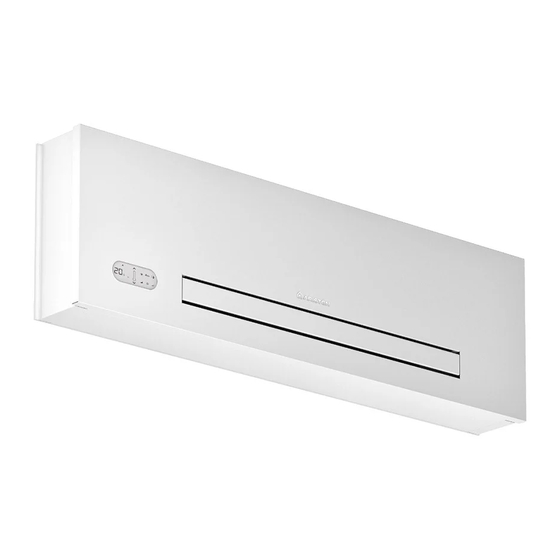
Page 5: Dimensioni D'ingombro
Dimensioni d’ingombro U.M. 15 WH 20 WH 25 WH Dimensioni 1.127 1.327 Dimensioni e pesi in trasporto Imballo M.E. 15 WH 20 WH 25 WH Dimensioni Peso 1.035 1.235 1.435 IT / 5... -
Page 6: Installazione
INSTALLAZIONE Posizionamento dell’unità Il ventilconvettore NIMBUS AQUASLIM WH può essere Accertarsi che: installato solo in posizione alta a parete, ad altezza minima la parete su cui si intende installare l’unità abbia una di 2 m. struttura e una portata adeguata;... -
Page 7: Apertura Frontale Per Installazione Apparecchio E
Apertura frontale per installazione apparecchio e collegamenti Rimuovere il pannello frontale estetico sollevandolo come in figura pannello frontale estetico IT / 7... - Page 8 Ruotare i filtri e sollevarli come in figura; Rimuovere i fianchi sollevandoli verso l'alto (B). Svitare le viti di fissaggio dei fianchi (C); filtri superiori vite di fissaggio fianco fianchi laterali IT / 8...
-
Page 9: Installazione A Parete Alta
Installazione a parete alta Per un'agevole installazione, soprattutto se si vuole in alternativa, se si riesce a curvare in modo agevole predisporre l'impianto in attesa della posa definitiva la tubazione (dipenderà dalla profondità della cassetta dell'apparecchio, consigliamo la predisposizione di installata), sarà... - Page 10 Utilizzare la dima di carta/cartone a corredo nella 3. Bloccare definitivamente le due staffe serrando confezione (alle pagine successive è riportata completamente le quattro viti. l'anteprima), e tracciare sulla parete la posizione delle 4. Verificarne la stabilità spostando manualmente le due staffe di fissaggio.
-
Page 11: Collegamenti Idraulici
Collegamenti idraulici U.M. 15 WH 20 WH 25 WH Diametro tubazioni La scelta ed il dimensionamento delle linee idrauliche Evitare di stringere troppo per non danneggiare sono demandati per competenza al progettista, che l’isolamento. dovrà operare secondo le regole della buona tecnica e delle legislazioni vigenti, tenendo conto che tubazioni Per la tenuta idrica delle connessioni filettate utilizzare sottodimensionate determinano un cattivo funzionamento. -
Page 12: Dima Di Installazione Quotata
Dima di installazione quotata IT / 12... - Page 13 IT / 13...
-
Page 14: Scarico Condensa
Scarico condensa La rete di scarico della condensa deve essere Nel caso si debba scaricare la condensa all’interno di opportunamente dimensionata (diametro interno tubo un recipiente, questo deve restare aperto all’atmosfera minimo 14 mm) e la tubazione posizionata in modo da ed il tubo non deve essere immerso in acqua, mantenere sempre lungo il percorso una determinata evitando fenomeni di adesività... -
Page 15: Riempimento Impianto
Riempimento impianto Durante l’avviamento dell’impianto assicurarsi che il è già stata alimentata precedentemente sarà necessario detentore sul gruppo idraulico sia aperto. Se ci si trova utilizzare l’apposito cappuccio per premere l’otturatore in mancanza di alimentazione elettrica e la termovalvola della valvola per aprirla. Evacuazione dell’aria durante il riempimento dell’impianto Aprire tutti i dispositivi di intercettazione dell’impianto caricamento fino al valore nominale previsto per... -
Page 16: Installazione E Collegamento Comandi
INSTALLAZIONE E COLLEGAMENTO COMANDI Touchpad e Telecomando Ventilconvettore DC Inverter per installazione a parete conformità alle norme nazionali vigenti. con comando elettronico autonomo a bordo macchina e telecomando. È possibile procedere all'allacciamento elettrico mediante un cavo incassato nella parete come in posizione indicata Prima di collegare il ventilconvettore assicurarsi che: nella dima di installazione (allacciamento consigliato per I valori della tensione e frequenza di alimentazione... -
Page 17: Istruzioni D'uso Con Touchpad E
ISTRUZIONI D'USO CON TOUCHPAD E TELECOMANDO Avvertenze Non appoggiarsi o peggio sedersi sulla scocca L’apparecchio non deve essere installato in locali dove del ventilconvettore per evitare di danneggiare si sviluppano gas esplosivi o dove vi sono condizioni l'apparecchio. di umidità e temperatura fuori dai limiti massimi definiti sul manuale di installazione. -
Page 18: Inserimento Batteria
Attraverso la pressione dei tasti è possibile impostare lasciarlo esposto ai raggi solari le varie funzioni (vedi paragrafo Descrizione del frapporre ostacoli tra il telecomando e l’apparecchio funzionamento). mentre si usa il telecomando stesso. Il telecomando fornito a corredo dell’apparecchio Inoltre: è... - Page 19 Tasto/Display Operazione I tasti del telecomando e del display touch screen eseguono la medesima funzione. Quando l’apparecchio è acceso sui 3 digit del display viene visualizzato il setpoint impostato. E’ possibile impostare tra 16 e 31°C il setpoint a cui il ventilconvettore porterà l’ambiente. Evitare di impostare una temperatura troppo bassa o troppo alta perché...
-
Page 20: Visualizzazione Allarmi A Display
Tasto/Display Operazione Controllo della velocità del ventilatore Premendo più volte questo pulsante la velocità cambia con la seguente sequenza: Minima, Media, Massima ed Automatica. Tanto maggiore è la velocità impostata, tanto maggiore è la resa dell’apparecchio, ma tanto minore è la sua silenziosità. -
Page 21: Gestione Dell'apparecchio In Caso Di Non Disponibilità Del Telecomando
Gestione dell’apparecchio in caso di non disponibilità del telecomando In caso di smarrimento del telecomando, esaurimento funzionare utilizzando i tasti del display touch screen a delle batterie o suo guasto l’apparecchio può essere fatto bordo macchina. Diagnosi degli inconvenienti l'Utente è... -
Page 22: Manutenzione Ordinaria
è indispensabile alcuni interventi e annuale per altri, dal Servizio Tecnico mantenere il ventilconvettore NIMBUS AQUASLIM WH di Assistenza, che è tecnicamente abilitato e preparato e sempre efficiente, sicuro ed affidabile nel tempo. Essa può inoltre disporre, se necessario, di ricambi originali. -
Page 23: Pulizia Filtro Aspirazione Aria
Pulizia filtro aspirazione aria Dopo un periodo di funzionamento continuativo ed in oppure quando si intende riavviare l’impianto dopo un considerazione della concentrazione di impurità nell'aria, periodo di inattività, procedere come descritto. Estrazione celle filtranti Estrarre le celle filtranti sollevandole leggermente e estrarre il filtro, tirando in senso verticale verso l’alto. -
Page 24: Pulizia Setti Filtranti
Pulizia setti filtranti aspirare la polvere dal filtro con un aspirapolvere E’ vietato l’uso dell’apparecchio senza il filtro a rete. lavare sotto acqua corrente, senza utilizzare detergenti o solventi, il filtro, e lasciare asciugare. L'apparecchio è dotato di un interruttore di sicurezza Rimontare il filtro sul ventilconvettore, prestando che impedisce il funzionamento del ventilatore in particolare attenzione ad infilare il lembo inferiore... -
Page 25: Anomalie E Rimedi
ANOMALIE E RIMEDI La ventilazione non si attiva anche se nel circuito In caso di fuoriuscite di acqua o di funzionamento idraulico è presente acqua calda o fredda. anomalo, staccare immediatamente l’alimentazione L’apparecchio perde acqua in funzione riscaldamento. elettrica e chiudere i rubinetti dell’acqua. L’apparecchio perde acqua nella sola funzione di raffreddamento. - Page 26 This manual has been written with the intention to inform you about how to install, use, and do the maintenance of the system in order to allow you to use your NIMBUS AQUASLIM WH system in the most performing way.
- Page 27 Avoid prolonged contact with the direct air flow. laws in force and the indications given by Ariston in the instructions leaflet supplied together with the appliance. Do not leave the room closed for long periods.
- Page 28 It is forbidden to dispose of or leave in the reach of The barred dustbin symbol appearing on the device children the packaging materials which could become indicates that the product must be disposed of a source of danger. separately from household waste once it reaches the end of its lifespan, and transferred to a waste disposal It is forbidden to climb onto the appliance or rest any site for electric and electronic equipment, or returned to...
- Page 29 Overall dimensions U.M. 15 WH 20 WH 25 WH Dimensions 1.127 1.327 Dimensions and weight during transportation Package M.E. 15 WH 20 WH 25 WH Dimensions Weight 1.035 1.235 1.435 EN / 29...
- Page 30 INSTALLATION Unit placement NIMBUS AQUASLIM WH fancoils have to be installed only Make sure that: in high wall position, above 2 meters. the wall on which you intend to install the unit has an appropriate structure and capacity; Avoid installing the unit near: the wall surface is not crossed by pipelines or power areas exposed to direct sunlight;...
- Page 31 Front opening for installing the device and connections Remove the aesthetic front panel by lifting it as shown in the figure; aesthetic front panel EN / 31...
- Page 32 Turn the filters and raise them as shown in the picture; Remove the side panels by lifting them (B). Loosen the screws fastening the sides (C); upper filters side screw side plates EN / 32...
- Page 33 High wall mount For smooth installation, especially if you want to another option if you can comfortably bend the set-up the system before you install the device, we pipeline (which will depend on the depth of the recommend installing a built-in cistern, as shown in the installed cistern) is to install the eurokonus connection figure;...
- Page 34 Use the paper template shown in full scale on the next 3. Firmly fasten the brackets by tightening the four page and trace the position of the two fixing brackets screws. on the wall. 4. Check stability by moving the brackets to the right and 2.
- Page 35 Hydraulic connections U.M. 15 WH 20 WH 25 WH Pipeline diameter The engineer is responsible for choosing the right water Avoid over-tightening the pipes to avoid damage to the lines and their size, in accordance with good installation insulation. practices and the applicable laws, keeping in mind that under-sized pipelines lead to poor system operation.
- Page 36 Installation template EN / 36...
- Page 37 EN / 37...
- Page 38 Condensate drain The condensate drain network must be sized appropriately must remain open and the pipe must not be immersed (minimum inner pipe diameter: 14 mm) and the pipeline in water to prevent adhesion and back-pressure that positioned so that it maintains a consistent slope along the would obstruct free flow.
- Page 39 Filling system When starting the system, make sure that the lock-shield and the thermal valve is already running, use its cap to on the hydraulic unit is open. If there is a power black-out press the valve shutter and open it. Air exhaust when filling the system Open all the system’s shut-off devices (whether rated specifications).
- Page 40 CONTROL PANEL INSTALLATION AND CONNECTION Touchpad and Remote control Fancoil DC Inverter for wall installation with autonomous compliance with the applicable national laws. electronic control on board machine and remote control. You can use a cable embedded in the wall in the position Before you connect the cooler-radiator, make sure traced with the installation template to make the electrical that:...
- Page 41 INSTRUCTIONS FOR USE WITH TOUCHPAD AND REMOTE CONTROL Warnings Do not lean or sit on the body of the cooler-radiator to The device must not be installed in rooms where there avoid damaging it. are explosive gases or where there are conditions of humidity and temperature out of the limits defined in Do not manually move the horizontal louver of the the installation manual.
- Page 42 You can set the various functions by pressing the keys placing obstacles between the remote control and the (see the keys function chapter). device while you are using the remote. The remote control supplied with the device is Moreover: designed to provide maximum sturdiness and if other devices are being used within the premises that exceptional functionality, but should nonetheless be are operated by remote control (TVs, radios, stereos,...
- Page 43 Key/Display Operation The keys of the remote control and touch-screen display perform the same function. When the unit is switched on, the preset set-point appears on the 3 digits of the display. The room temperature set-point can range between 16 and 31 °C. Do not set a temperature that is too low or too high is harmful to health and is an unnecessary waste of energy.
- Page 44 Key/Display Operation Fan speed control Repeatedly pressing this key will change the speed with the following sequence: Minimum, Medium, Maximum and Automatic. The higher the set speed, the higher the device’s performance (but also the louder the noise). If you set the speed to Automatic (you will notice the 3 speed bars slide on the display), the micro-processor will adjust the speed automatically (the higher the difference between the room temperature and the set temperature, the higher the speed).
- Page 45 Operating the unit if the remote control is not available If you lose the remote control, the batteries run out or the with the keys on the touch-screen display on-board the remote stops working, you can be operate the device machine.
- Page 46 Routine maintenance is essential to keep the cooler- other tasks) by our Technical Customer Service, which is radiator NIMBUS AQUASLIM WH always efficient, safe and qualified for such tasks and which can also supply original reliable over time. Routine maintenance can be performed spare parts, if necessary.
- Page 47 Cleaning the air suction filter After prolonged operation and so as to factor the to restart the system after prolonged disuse, proceed as concentration of impurities in the air, or when you plan follows. Extraction of filter cells Remove the filter cells by lifting them slightly and Remove the filter by pulling it horizontally and upwards.
- Page 48 Filter media cleaning suction the dust from the filter using a vacuum cleaner It is forbidden to use the device without its mesh filter. wash the filter with running water without using any detergents or solvents and then let it dry. The device features a safety switch hat prevents the Remount the filter on the cooler-radiator, paying fan from starting if the mobile panel is incorrectly...
- Page 49 TROUBLESHOOTING The ventilation does not start even if the water circuit In case of water leaks or abnormal operation, is filled with hot or cold water. disconnect the device from power supply immediately The device is losing water in heating mode. and close the water taps.
- Page 52 Ariston SpA Viale Aristide Merloni, 45 60044 Fabriano (AN) Italy Telefono 0732 6011 Fax 0732 602331 info.it@aristonthermo.com Servizio Clienti Ariston Telefono 0732 633528...
Need help?
Do you have a question about the NIMBUS AQUASLIM WH and is the answer not in the manual?
Questions and answers