Table of Contents
Advertisement
Available languages
Available languages
Quick Links
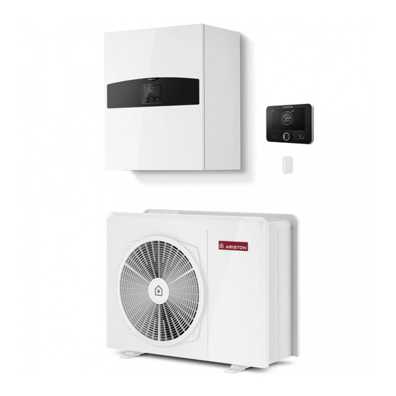
NIMBUS HYBRID S NET R32
QUICK START GUIDE
EN WARNING!
This document summarises the information contained in the manual TECHNICAL
INSTRUCTIONS FOR INSTALLATION AND MAINTENANCE.
We refer to this manual, which must be read carefully before proceeding with the
INSTALLATION, FOR THE RELEVANT SAFETY INFORMATION.
FR
ATTENTION !
Ce document est un récapitulatif des informations fournies dans le manuel INSTRUCTIONS
TECHNIQUES D'INSTALLATION ET D'ENTRETIEN.
Veuillez vous référer à ce manuel pour les INFORMATIONS DE SÉCURITÉ ET LE LIRE
ATTENTIVEMENT AVANT DE PROCÉDER À L'INSTALLATION.
Advertisement
Table of Contents

Related Manuals for Ariston NIMBUS HYBRID S NET R32


Summary of Contents for Ariston NIMBUS HYBRID S NET R32
- Page 1 NIMBUS HYBRID S NET R32 QUICK START GUIDE EN WARNING! This document summarises the information contained in the manual TECHNICAL INSTRUCTIONS FOR INSTALLATION AND MAINTENANCE. We refer to this manual, which must be read carefully before proceeding with the INSTALLATION, FOR THE RELEVANT SAFETY INFORMATION.
-
Page 2: System Description
SYSTEM DESCRIPTION To install... 4 HEATING AND COOLING SOLUTION WALL-MOUNTED MODULE Material supplied together with the units: Technical documentation (Installer manual, User manual, this Quick Start Guide, Technical data, Energy labels, Circuit diagrams, Warnings sheet), cable ties; Material for mounting the system interface (mounting plate, screws and plugs); Material for mounting the wall-mounted module (horizontal mounting plate, template, screws and plugs);... -
Page 3: Preliminary Checks
CHECKLIST (1/3) The external and internal units must be installed by a qualified technician. For detailed instructions, refer to the installation manual. PRELIMINARY CHECKS Have you cleaned the system and the boiler (if present)? Have you checked the water quality? Where are you installing the units? Make sure that: •... -
Page 4: External Unit
CHECKLIST (2/3) The external and internal units must be installed by a qualified technician. For detailed instructions, refer to the installation manual. EXTERNAL UNIT Did I position the unit outside? Did I mount the vibration damper? Have you positioned the unit on a strong, level base, with easy access for maintenance? Have you installed a shield to protect the unit against draughts? Are you sure the flow of air is unobstructed? Are you sure the supporting structure can bear the weight of the external unit? -
Page 5: Plumbing Connections
CHECKLIST (3/3) The external and internal units must be installed by a qualified technician. For detailed instructions, refer to the installation manual. PLUMBING CONNECTIONS Have you checked that the water circuit pressure never exceeds 5 bar, or installed a pressure reducer at the system’s intake if it does? Have you filled the system to less than 3 bar (recommended pressure = 1.2 bar)? Have you checked the tightness of the system? - Page 6 LAYOUT WITH COMBI BOILER - HEATING MODE OPERATION Outdoor unit Symbol Description Indoor unit System flow Sensys HD interface Shutter valve System return Sludge filter Communication connection System expansion vessel Bypass (optional) Electrical connection Outdoor Sensor 3-way valve Domestic cold water inlet 10 Circulation pump Domestic hot water outlet 11 Finned heat exchanger...
- Page 7 LAYOUT WITH SYSTEM BOILER - HEATING MODE OPERATION Outdoor unit Symbol Description Indoor unit System flow Sensys HD interface Shutter valve System return Sludge filter Communication connection System expansion vessel Bypass (optional) Electrical connection Outdoor Sensor 3-way valve Domestic cold water inlet 10 Siphon Domestic hot water outlet 11 Non-return valve...
-
Page 8: Electrical Wiring
ELECTRICAL WIRING MODBUS ATG BUS DHW HEATER ANODE TA1 TA2 EBUS2 PM AUX OPEN IN AUX 2 STE BUF THERM AUX 1 AUX 2 AUX 1 IN 1 IN 2 AUX 4 AUX 3 ⏚ +24V FB STH +24V 4. 5. 8. -
Page 9: Main Parameters
MAIN PARAMETERS BOILER SETTINGS par. 2.2.7 Boiler Hybrid Set to 2 --> Enabled HYDRAULIC SCHEME AND RELATED PARAMETER SETTING 1.0.2 - Tank Management WHB COMBY WHB SYSTEM (TANK) 0 - None 1 - Tank with NTC par. 2.2.8 Boiler version set 2 -->... - Page 10 HEATING PARAMETERS par. 1.3.2 ECO / COMFORT select eco-comfort degree: eco/comfort: Eco plus / Eco / Average / Comfort / comfort plus par. 1.0.6 AUTO function Absent / Present BUFFER SCHEME PARAMETERS par. 20.0.0 Buffer Activation OFF / ON par. 20.0.1 Buffer charge mode partial load (1 sensor) / full load (2 sensors) par.
-
Page 11: Description Du Système
DESCRIPTION DU SYSTÈME Si j’installe... 4 SOLUTION DE CHAUFFAGE Matériel fourni avec les unités : Documentation technique (notice installateur, notice utilisateur, ce guide de démarrage rapide, paramètres techniques, étiquettes énergie, schéma des circuits, fiche des recommandations), attaches de câble ; Matériel pour le montage de l’interface du système (plaque de support, vis et chevilles) ;... -
Page 12: Liste De Contrôle
LISTE DE CONTRÔLE (1/3) L’installation des unités extérieure et intérieure doit toujours être réalisée par un technicien qualifié. Consulter la notice d’installation pour le détail des différentes étapes. VÉRIFICATIONS PRÉLIMINAIRES J’ai effectué de nettoyage du système et du chauffe-eau (s’il est présent) ? J’ai vérifié... -
Page 13: Unité Extérieure
LISTE DE CONTRÔLE (2/3) L’installation des unités extérieure et intérieure doit toujours être réalisée par un technicien qualifié. Consulter la notice d’installation pour le détail des différentes étapes. UNITÉ EXTÉRIEURE Ai-je placé l'unité à l'extérieur ? Ai-je monté le support antivibratile ? J’ai placé... -
Page 14: Première Mise En Marche
LISTE DE CONTRÔLE (3/3) L’installation des unités extérieure et intérieure doit toujours être réalisée par un technicien qualifié. Consulter la notice d’installation pour le détail des différentes étapes. RACCORDEMENTS À L’EAU J’ai vérifié que la pression du réseau eau ne dépasse pas 5 bar, autrement j’ai prévu un réducteur de pression à l’entrée de l’installation ? J’ai remplis l’installation à... - Page 15 SCHÉMA AVEC CHAUDIÈRE COMBI - FONCTIONNEMENT CHAUFFAGE Unité extérieure Symbole Description Unité intérieure Départ installation Interface Sensys HD Vanne d’arrêt Retour installation Pot de décantation Connexion communication Vase d’expansion chauffage By-pass (en option) Liaison électrique Sonde extérieure Vanne 3 voies Entrée eau froide sanitaire 10 Circulateur Sortie eau chaude sanitaire...
- Page 16 SCHÉMA AVEC CHAUDIÈRE SYSTEM - FONCTIONNEMENT CHAUFFAGE Unité extérieure Symbole Description Unité intérieure Départ installation Interface Sensys Vanne d’arrêt Retour installation Pot de décantation Connexion communication Vase d’expansion chauffage By-pass (en option) Liaison électrique Sonde extérieure Soupape à 3 voies Entrée eau froide sanitaire 10 Siphon Sortie eau chaude sanitaire...
-
Page 17: Raccordements Électriques
RACCORDEMENTS ÉLECTRIQUES MODBUS OPEN ATG BUS DHW HEATER ANODE TA1 TA2 EBUS2 PM AUX IN AUX 2 STE BUF THERM AUX 1 AUX 2 AUX 1 IN 1 IN 2 AUX 4 AUX 3 ⏚ +24V FB STH +24V 4. 5. 8. - Page 18 RÉGLAGE DES PRINCIPAUX PARAMÈTRES: RÉGLAGE DES PARAMÈTRES DE LA CHAUDIÈRE paramètre 2.2.7 Chaudière hybride sélectionner 2 --> activée RÉGLAGE DU SCHÉMA HYDRAULIQUE ET PARAMÈTRES ASSOCIÉS 1.0.2 - Gestion du réservoir CHAUDIÈRE COMBI CHAUDIÈRE SYSTEM (AVEC BALLON D’EAU CHAUDE) 0 - None 1 - Tank with NTC paramètre 2.2.8 version chaudière sélectionner 2 -->...
- Page 19 PARAMÈTRES CHAUFFAGE paramètre 1.3.2 Mode chauffage sélectionner le niveau eco/comfort : Eco plus / Eco / Moyen / Confort / Confort plus paramètre 1.0.6 Fonction AUTO Absent / présent PARAMÈTRES SCHÉMA BALLON DE STOCKAGE paramètre 20.0.0 Activation charge ballon de stockage OFF / ON paramètre 20.0.1 Type de charge du ballon de stockage charge partielle (1 sonde) / charge complète (2 sondes)
- Page 20 Viale Aristide Merloni, 45 60044 Fabriano (AN) Italy Tel. +39 0732 6011 Fax +39 0732 602331 www.ariston.com...
Need help?
Do you have a question about the NIMBUS HYBRID S NET R32 and is the answer not in the manual?
Questions and answers