
Related Manuals for Noblelift FE4P16-35N-SMS-001


Summary of Contents for Noblelift FE4P16-35N-SMS-001
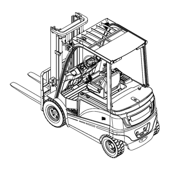
- Page 1 We Promise, We deliver FE4P16-35N-SMS-001 Service Manual Battery Weight Balanced Forklift...
-
Page 2: Table Of Contents
We Promise, We deliver 1.General 1-1 How to Use This Manual............11 1-1-1 Composition of This Manual........11 1-2-2 Definitions of Warning Signs........12 1-2 Glossary................13 1-3 Appearance and Specifications..........18 1-4 Safety Notes................22 1-5 Maintenance................31 1-6 Lube..................35 1-6-1 Specification of Lubricant..........35 1-7 Disassembly/Assembly Instructions ........37 1-8 Standard Torque..............51 1-8-1 Standard Torque for Bolts and Nuts......51 1-8-2 Standard Torque for Fastenings ........53... - Page 3 We Promise, We deliver 2-2-2 Functions..............60 2-2-3 Test................61 2-2-4 Maintenance.............65 2-2-5 Disassembly and Installation........66 2-2-6 Lithium Battery............68 2-3 Emergency Switch .............74 2-3-1 Appearance and Specifications........74 2-3-2 Functions..............74 2-4 Controller and Related Equipment........75 2-4-1 Appearance and Specifications........75 2-4-2 Circuits and Functions..........75 2-4-3 Diagnosis and Troubleshooting........80 2-4-4 Test................81 2-4-5 Disassembly and Installation........84...
- Page 4 We Promise, We deliver 2-6-2 Functions..............90 2-6-3 Description and Function...........91 2-7 CURTIS Handheld Programmer .........91 2-7-1 Operation Cautions............91 2-7-2 Process of Vehicle Fault Reading......92 2-7-3 Vehicle signal Detection..........92 2-7-4 Contents of CURTIS Handheld Unit Menu....93 2-8 Troubleshooting to Each Fault Code ........99 3.Driving/Braking System 3-1 General ................105 3-1-1 Component....
- Page 5 We Promise, We deliver 3-4 Accelerator................116 3-4-1 Appearance and Specifications........116 3-4-2 How Does This Work ..........117 3-4-3 Disassembly and Installation........118 3-5 Combination Switch..............119 3-5-1 Appearance and Specifications........119 3-5-2 How Does This Work ..........119 3-6 Service Brake Pedal.............123 3-6-1 Appearance and Specifications........123 3-6-2 How Does This Work ..........123 3-6-3 Air Removal of Brake Oil ..........124 3-6-4 Adjustment of Brake Pedal .........125...
- Page 6 We Promise, We deliver 3-7-4 Adjustment Parking Brake Switches......142 3-7-5 Disassembly/Installation of Parking Brake Bar...143 3-8 Troubleshooting ..............145 3-8-1 Drive Motor ...............145 3-8-2 Drive Axle ..............147 3-8-3 Service Brake............148 3-4 Parking Brake ..............149 4.Hydraulic System 4-1 General 4-1-1 Component....
- Page 7 We Promise, We deliver 4-3-3 Disassembly and Installation........163 4-4 Multiway Valve and Priority Valve 4-4-1 Appearance and Specifications.........167 4-4-2 How Does This Work ..........168 4-5 Hydraulic Tank and Filter. 4-5-1 Appearance and Specifications.........171 4-5-2 How Does This Work ..........172 4-5-3 Replacement of Hydraulic Tank and Filter....174 4-6 Troubleshooting ..............175 4-6-1 Pump Electric Motor...........175 4-6-2 Main Hydraulic Pump..........177...
- Page 8 We Promise, We deliver 5-2-4 Disassembly/Installation of Multiway Valve....197 5-3 Mast 5-3-1 Appearance and Specifications........199 5-3-2 How Does This Work ..........200 5-3-3 Service of Pallet Fork ..........203 5-3-4 Side Shifter...............209 5-3-5 Service of Chains............213 5-3-6 Service of Tilting Cylinder ........218 5-3-7 Service of Main Lifting Cylinder.........224 5-3-8 Service of Transportation.....
- Page 9 We Promise, We deliver 6-2-3 Air Removal of Steering System........248 6-2-4 Pressure Test of Steering System......249 6-2-5 Disassembly/Installation of Steering Wheel Cover..252 6-2-6 Disassembly/Installation of Steering Wheel....253 6-2-7 Disassembly/Installation of Steering Wheel Column..255 6-3 Steering Axle 6-3-1 Appearance and Specifications.........256 6-3-2 How Does This Work ..........257 6-3-3 Disassembly/Installation/Adjustment of Rear Wheels and Wheel Hub....
- Page 10 We Promise, We deliver 8-2 Disassembly/Installation of Overhead Cover.......273 8-3 Disassembly/Installation of Floor..........274 8-4 Disassembly/Installation of Top Cover and Counterweight...275 9.Battery Charger 9-1 Introduction of Battery Charger..........277 9-2 Introduction of Control Panel ..........278 9-3 General Faults of Battery Charger.........280...
-
Page 11: How To Use This Manual
We Promise, We deliver 1-1 How to use this manual 1-1-1 Composition of this manual This service manual mainly provides engineers and technicians service information for forklift repair and maintenance, which excludes vehicle operation instructions. The introduction section of this manual introduces the functions of the vehicle with particular attention to its different components. -
Page 12: Definitions Of Warning Signs
We Promise, We deliver Section Headings General Electronic System 3 Driving/Braking System Hydraulic System Lift/Tilt/Auxiliary System Steering System Schematic Diagram Miscellaneous Battery Charger 1-1-2 Definitions of Warning Signs The following three warning signs are applicable to this Manual: "Danger", "Warning" and "Caution". Each label is intended to indicate the severity and nature of the potential hazard, the consequences, as well as preventive measures against hazards. -
Page 13: Glossary
We Promise, We deliver 1-2 Glossary The terms referred in this service manual and their descriptions are as follows. Item Descriptions Accelerator A device that converts mechanical motion to an analog voltage mode and transmit to a controller to control the speed at which a vehicle is driven Actuator A device (e.g. - Page 14 We Promise, We deliver Condenser A device for short-time electrical energy storage. Goods Holder A supporting structure on which a fork is mounted Check Valve A valve that allows oil to flow in one direction rather than in the other Circuit A path along which The current can travel from the positive (+) side of the source to the negative (-) side.
- Page 15 We Promise, We deliver controller. Filter A mechanical device used to accommodate a filter element, or a filter device used to prevent contamination flow through a system Flow Protector A valve that prevents the hydraulic oil extraction of the control valve from the lifting cylinder when the hydraulic line breaks unexpectedly, which prevents the backstay from dropping suddenly.
- Page 16 We Promise, We deliver Suffocated The part of an electric brake in which the current generated is directed back to the armature. Port An input or output point on a hydraulic element Power Socket A connecting socket that installed on the forklift. Pressure a fluid force as per unit area Proximity Detector...
- Page 17 We Promise, We deliver hydraulic system Voltage A measurement unit of electrodynamic force. A volt is the force that required for an ampere of current to pass through an ohmic resistor in a circuit. Watt A unit of power measurement. The power for one volt to push one ampere of current through an ohmic resistor.
-
Page 18: Appearance And Specifications
We Promise, We deliver 1-3 Appearance and Specifications... - Page 19 We Promise, We deliver...
- Page 20 We Promise, We deliver Model FE4P16 N FE4P25 N Drive Mode Electromotion Operating Mode Seated Rated Capacity of Load 1600 2500 Q(kg) Center Distance of Load C(mm) Front Overhang x(mm) Wheel Base 1360 1360 y(mm) Self weight with battery 3120 3120 Bridge load of full load, 3950/770...
- Page 21 We Promise, We deliver (mm) Length of body(to pallet 2061 fork end) (mm) Total width 1150 (mm) Size of pallet fork 35/100/920 s/e/l(mm) Width of fork arm carrier (mm) Wheelbase centre clearance from ground (mm) Radius of turning 1880 Wa(mm) Running speed(full/empty) 13/15 Km/hr...
-
Page 22: Safety Notes
We Promise, We deliver 1-4 Safety Notes The following safety sections contains the following subsections: general, personal safety, maintenance safety, compressed air hazards, hydraulic oil hazards, mechanical hazards, electrical hazards, and fire & burning hazards. Each heading are attached with the precautions you should take for your safety while working in your vehicle. - Page 23 We Promise, We deliver Make sure that all safety rules, regulations and instructions are followed when performing maintenance tasks. Special attention is required to the danger warning in this manual, which will detail you the potential dangerous conditions. Do not assume that you can replace the steps outlined in this manual with your previous maintenance experience of similar models.
- Page 24 We Promise, We deliver Personal Safety Do not operate or service a vehicle without authorization or training Do not operate or service a vehicle after alcohol or drugs taking which will impair your judgement. If you have any disease or condition that restricts physical activity, please do not operate or service the vehicle.
- Page 25 We Promise, We deliver and an air breathing device is advised when painting. Welder gloves, welding masks/goggles, aprons and other suitable welding clothing are required when welding. Security of Service Pre-service Make sure that the vehicle is kept in a clean, open environment, and is free from any traffic and personnel.
- Page 26 We Promise, We deliver Disassembly and Installation Make sure the working environment is clean, clean and dry before installing the vehicle. When using steps, ladders or walkways for installation or removal, please face the vehicle. Please follow these steps and grab the handle to install or remove parts.
- Page 27 We Promise, We deliver should not be loaded laterally during lifting operation. Disassembly/Assembly Make sure that the assembly/disassembly site is kept clean and dry and that hand tools are kept clean. When tightening/loosening bolts and nuts, please use a properly sized wrench and always pull towards the body.
- Page 28 We Promise, We deliver cleaning operation。 The maximum air pressure for cleaning must be less than 205 kPa (30 psi). Hazard of Hydraulic Oil Please follow the following safety instructions for hydraulic system maintenance carefully. Oil removal under pressure, even if the pinhole size leaks, can penetrate the body elements and cause serious damage and possibly death.
- Page 29 We Promise, We deliver ensure that all heat shields, fixtures and guards are properly installed to avoid overheating, vibration or friction with other components during operation. Lines must be installed correctly to prevent oil from being sprayed into the shield on the hot exhaust components in case of any pipe or seal failure. Mechanical Hazards Keep all the objects away from the fan blades, or they will throw or cut any object or tool that falls or is pushed in.
- Page 30 We Promise, We deliver Electrical Hazards Do not damage any wire during disassembly operation. When re-installing wiring, make sure it is installed correctly Do not wire to any oily cable. Do not smoke or expose batteries to any spark or flame when checking, charging or repairing the batteries.
-
Page 31: Maintenance
We Promise, We deliver nonflammable solvent. Remove all residual flammable materials from the forklift and then collect, like fuel and oil. 1-5 Maintenance The following provides the key items and replaceable components to be checked during maintenance intervals. Note: all maintenance and repair should be carried out by a qualified authorized engineer except for the routine inspection of the vehicle driver. - Page 32 We Promise, We deliver Necessary Check as Required Item Inspection Standard and Method Instrument Board Press Enter You can access diagnostic mode by pressing this button while driving Idler Wheel Measure the distance from the bottom of the inner frame to the bottom of Goods Holder the sliding frame bearing to ensure a upright inner frame and then adjust the squeezed roller.
- Page 33 We Promise, We deliver Battery Check the battery box for loose connections, worn cables and limits on properly secured battery limits. Clean the top of the battery. If necessary, clean the top of the battery with a solution of 0.5 kilograms (1 pound) of baking soda and 4 liters (1 gallon) of hot water.
- Page 34 We Promise, We deliver needed. Check for loose wiring and secure it as needed. Parking Brake Check the parking brake to ensure that the vehicle is stationary at a 15% gradient and repair or replace if necessary. Hydraulic Oil Check the hydraulic oil level and refill if necessary. Check every 1,000 service hours or every 6 months Item Inspection Standard and Method...
-
Page 35: Lube
We Promise, We deliver 1-6 Lube The following is a detailed description of the lubricant as required and the parts to be lubricated. 1-6-1 Lubricating Oil Specification The following lubricants are recommended for chains and connecting rods: Item Specification DIN 51825 Standard Oil and Grease Hydraulic Oil (HYDO)... - Page 36 API GL-4 or SAE 80W oil is acceptable Note: Noblelift does not mix multi-stage oils for transmissions. Multistage oils with high molecular weight polymers as vi improvers lose their viscosity effectiveness due to the permanent and temporary shear of vi improvers and...
-
Page 37: Disassembly/Assembly Instructions
We Promise, We deliver 1-7 Instructions of Disassembly/Assembly The following parts of Disassembly/Assembly include the following sections: the preparation before disassembly, the inspection and test before disassembly, the matters to be attended during disassembly, the matters to be attended after disassembly, the matters to be attended during assembly, the handling of common parts and hydraulic piping fittings. - Page 38 We Promise, We deliver Be sure to record any problems before starting the disassembly, which can prevents unnecessary disassembly, loss of replacement parts, and repeated failures as caused by the same problem. To prevent failures, record failures and replace required parts are required. The following information shall be also checked and recorded: Vehicle model number, serial number and operation hours Reasons of the vehicle needs to be dismantled...
- Page 39 We Promise, We deliver Notes for disassembly Disassembly: Determine the way of parts assembly (front/rear, left/right and up/down) for the sequence of disassembly. Before starting to disassemble parts, attention shall be paid to the join points of parts with arrow marks to avoid misplacing parts during assembly Please use the right tools to remove specific parts.
- Page 40 We Promise, We deliver Keep the distance Make sure that the installed spacers and gaskets will produce the required specific clearance. Remove pressure fittings Remove any dent or mark that caused by area hammering and polishing. If any pressing part is released, please identify and eliminate the cause to avoid problems during assembly.
- Page 41 We Promise, We deliver When using dangerous chemical cleaners, be careful to avoid a skin or eye contact. Used oil should be disposed of in designated containers at designated locations. Dustproof A dust cover is advised to keep cleaned parts free of dust and contaminants and to block up the ends of all pipes.
- Page 42 We Promise, We deliver Before pressing parts, the surface shall be lubricated with lube. Tighten the bolts and nuts To ensure a uniform torque of bolts and nuts, the tighten order shown in figure 1-19 shall be followed and then the other end of the other side shall be tightened.
- Page 43 We Promise, We deliver Assembly Inspection At each step of the assembly process, each part's number shall be checked and recorded. Reassemble the gaskets Install the gasket and washer in the same position as before, and then check the gap for correctness. Assembly adjustment If no adjustments are required, assemble them to the same length as before Assemble pressed parts...
- Page 44 We Promise, We deliver Handling the general parts Handling the packaging Packing, as well as gaskets &copper packing should be replaced as instructed. After using the adhesive, please assemble the gasket specified in this maintenance manual. The followings shall be noted when applying the adhesive to the gasket: Old adhesive, scratches, dust, paint and grease shall be thoroughly removed from the washer surface.
- Page 45 We Promise, We deliver the parts list. For example, the O rings used in engine oil are made of special materials, such as silicone rubber, and are resistant to heat and aging. Installing different types of O-rings in this situation can cause serious damage to the system and its components.
- Page 46 We Promise, We deliver After the oil seal is inserted, the inclination shall be checked (tilt tolerance: 0.2 mm /00 mm, diameter 0.008 in. /3.937 in.).When applying adhesive to oil seal, make sure that there is no adhesive in contact with the lip surface. All residual adhesive shall be removed from the guide and fixture before inserting another seal.
- Page 47 We Promise, We deliver hot insertion, the bearing shall be heated to 120℃(248℉). However, please note that excessive heating can reduce the hardness of the bearing surface. When inserting non-split bearings with inner and outer rings with reasonable tolerances, the fixture shown in figure 1-24 shall be applied and both inner and outer rings shall be pressed.
- Page 48 We Promise, We deliver 6. Start up the engine. 7. Move the control lever to full position. 8.Inspect the hose during tool movement. Make sure that the hoses do not contact any machines or other hose. 9. Shut off the motor 10.
- Page 49 We Promise, We deliver Note: if the joint is a connector (direct connector), then the lock nut on the main body shall be replaced by the hexagon nut. To install this type of joint, the hexagon joint shall be tightened to the surface of the parts into which it enters. Tighten accessories of other types Pipe fittings (shear sleeve) of high load: please turn the nut with a wrench until a slight reduction in torque is felt after the pipe passes through the nut and...
- Page 50 We Promise, We deliver thread of the body. As soon as the fitting is removed and reinstalled, the remaining space will be available. Figure 1-26 Figure 1-27 Figure 1-28 Figure 1-29 Flexible fittings: please place the nuts and sleeves on the pipes and push the pipes as far as possible into the countersunk holes of the fitting bodies.
-
Page 51: Standard Torque
We Promise, We deliver 1-8 Standard Torque 1-8-1 Standard torque of bolts and nuts Be careful that the metric and British size fasteners shall not be mixed in used. Mismatched or incorrect fasteners may cause damages or malfunctions to the vehicle or personal injuries. Exceptions to these torques may be provided in the service manual if required. - Page 52 We Promise, We deliver marked on the heads (e.g. 8.8 or 10.9) as shown in figure 1-30. The following table are listing the standard torques for typical bolts, nuts and the taper bolts as shown in figure 1-31. For metric fasten...
-
Page 53: Standard Torque For Fastenings
We Promise, We deliver 1-8-2 Standard torques for fastening fittings Standard torques for O-ring surface seal fittings... - Page 54 We Promise, We deliver...
- Page 55 We Promise, We deliver Thread fittings for air conditioning and conical pipes...
-
Page 56: Electronic System
We Promise, We deliver 2 Electronic System 2-1 General This model is equipped with an electrical system with the following components: 1. The battery supplies the power to the electrical system [Section 2-2] 2. The emergency switches may be pressed in emergency to turn off all DC and AC circuits [Section 2-3] 3.Motors, controllers, and associated equipment are providing the necessary drive and pump power to the vehicle based on their interactions with sensors,... -
Page 57: Communication Protocol
We Promise, We deliver 8. The handheld programmer provides the same functions as the instrument board, but are detailed [sections 2-7] 2-1-2 Communication Protocol To enable all electrical equipment in the vehicle and provide diagnostic and parameter calibration functions to the user, data shall be shared between these controllers and instrument equipment. - Page 58 We Promise, We deliver referred to sections 2-7. Such CAN communication effectively overcomes the shortcomings of the widely used point-to-point communication based UART...
-
Page 59: Battery (Lead Battery)
We Promise, We deliver (universal asynchronous receiver/sender) system. The UART systems are limited by the one-to-one communication between individual devices in the number of communication devices, wiring availability and vehicle performance improvement. CAN and UART communication are compared in the figure above. - Page 60 We Promise, We deliver REMA95044-01 Battery cable length B+:1450mm B-:1450mm Battery cable size More then 2/0 GA(60 mm 2 ) Specific gravity depends on temperature Temperature Charging Level...
-
Page 61: Functions
We Promise, We deliver 2-2-2 Function A. Characteristics of lead batteries This model uses a lead battery as a power source for its electrical system. The lead battery is mainly composed of positive plate, negative plate, electrolyte, separator, battery tank, battery cover, electrode, liquid injection cover, etc. -
Page 62: Test
We Promise, We deliver 2-2-3 Test A. Battery condition check Weak batteries can cause problems in the controller and power circuit. The battery shall be ensured with a good condition before troubleshooting other areas. Preliminary steps Verify the polarity on the battery connector and control panel for correctness. The positive terminal cable shall be located at the line fuse while the negative terminal shall be located at the negative terminal of the control panel. - Page 63 We Promise, We deliver repaired before the troubleshooting. When the vehicle does not work and the battery is suspicious. Battery pressure drop test 1.The voltage of each battery shall be measured when the vehicle is powered on and the pump motor is running. 2.
- Page 64 We Promise, We deliver shall be properly charged or repaired B. Insulation check of battery case Any resistance between any point of the wiring in forklift truck and car body should be at least 10000 Ω or higher. A short circuit in the battery case may cause many faults. Because the battery may have chassis leakage, A chassis short circuit in the forklift wiring may cause problems.
-
Page 65: Maintenance
We Promise, We deliver 2-2-4 Maintenance Battery maintenance and service is essential to maximize the service life of battery and efficient vehicle operation. Regular inspection and maintenance will extend the service life of the battery. Special attention should be paid to the following rules: 1. -
Page 66: Disassembly And Installation
We Promise, We deliver temperature shall not exceed 55° C (131° F) during operation or charging. Overcharging of the battery will lead to an overheating of the battery, causing the battery bulge and other adverse phenomena. The battery has the longest service life when the electrolyte temperature is maintained at 25 °... - Page 67 We Promise, We deliver 1. Vehicles Parking 2. Drop the fork and tilt the mast forward until the tip of the fork touches the ground. 3. Close key switch 4. Disconnect the battery connector. 5. Position the operating column vertically and move the seat back completely.
-
Page 68: Lithium Battery
We Promise, We deliver 2-2-6 Lithium Battery 1 Technical parameters and description of lithium battery... - Page 69 We Promise, We deliver Description of lithium battery charging port Positive pole of Dc power which connects DC power positive pole and battery positive pole Positive pole of Dc power which connects DC power positive pole and battery positive pole Charging input CAN-L...
- Page 70 We Promise, We deliver Description of lithium battery debugging port 10.1.2 Fault analysis and description of lithium battery Fault repair list of battery pack system Fault type Preliminary estimate Test method Failure confirmation Countermeasure 1.If the resistance is measured to be infinite, the the CAN 1.
- Page 71 We Promise, We deliver for breakover. 2.If there is resistance and is far bigger than 120 Ω, damage may be indicated inside the BMS CAN chip. If there is an output, the 1.Disconnect the discharge plug locomotive may have Check the locomotive and start the battery pack an internal circuit error communication and...
- Page 72 We Promise, We deliver 1. Check if the 12V charging Replace the cable The conduction is socket harness , GND, CANH harness of the charging abnormal and CNAL harness is normal socket The battery pack 1. Abnormal 2. Connect the charger to check cannot be communication with the fault code of the charger...
-
Page 73: Functions
We Promise, We deliver 3. Disconnect the battery pack BMS fault Replace BMS from the connection to the forklift and the wiring harness on the switch. 2-3 Emergency Switch 2-3-1 Appearance and Specifications Item Specification Part Number 1010434024 CE4T-10R-01 2-3-2 Function The emergency switch is used to shut off the current in the electrical system in case of emergency,... -
Page 74: Emergency Switch
We Promise, We deliver and thereby stopping the operation of the vehicle. When pressed the key, all DC and AC circuits are open except the speaker circuit. When the emergency switch is opened, the positive terminal of the battery is disconnected from the key switch, thus cutting off all the load power supplied through the key switch. -
Page 75: Circuits And Functions
We Promise, We deliver voltage then the voltage is high; if temperature the rising edge >4.4V, then the voltage is high KSI input current <1.0A Storage ambient -40℃ to 50℃ temperature Input current of logical <10mA Current limit The current is limited at 85℃ overtemperature and will cut off at 95℃... - Page 76 We Promise, We deliver Critical Power Supply of Controller This model is equipped with a drive motor and a pump motor, which are controlled by different controllers. The forklift is powered by the controllers through key switches and then turned on. Current to the contactor of the line Power supply of controller Once the controller is energized, a magnetic coil built into the line contactor will receive power from the driven motor controller.
- Page 77 We Promise, We deliver Overcurrent. The two controllers are connected through the following sensors, switches, relays and actuators. Key switch Emergency Switch Forward/revise units Accelerator Seat Switch Brake pedal switch Parking brake switch Hydraulic control switch Horn relay These devices provide DC power and interact with controllers that activate or receive data based on a number of parameter settings to control the motor.
- Page 78 We Promise, We deliver function of the controller enables the a long-time operation of electric forklift at a low speed. 2. The acceleration rate is adjustable. The acceleration rate refers to the "soft and hard" feeling of accelerator pedal when operating electric forklift. By setting the acceleration rate, the forklift can meet the requirements of acceleration operation in different working conditions.
- Page 79 We Promise, We deliver maximum driving speed of electric forklift can prevent any overloading of traction motor due to high speed. 6.Static reply switch off. In the event that the seat switch or key switch is disconnected, the control will be turned off and the directional control lever shall be pushed back into the neutral position to restart.
-
Page 80: Diagnosis And Troubleshooting
We Promise, We deliver 2-4-3 Diagnosis and Troubleshooting There is a way to view the current fault code without a instrument board or handheld programmer: a built-in LED light is set on each controller to indicate the entire fault code list. Each code consists of two digits. -
Page 81: Test
We Promise, We deliver 2-4-4 Test A. Controller The diode voltage of AC MOSFET circuit inside the controller shall be tested and checked for any burn out damage. According to the table below, each test item shall be tested repeatedly for more than 3 times. - Page 82 We Promise, We deliver Test 2:Read the voltage of the diode to U, V and W, and the black lead to B + with red wires. Notes: The multimeter pointers shall not be inverted in use...
- Page 83 We Promise, We deliver B. Line contactor and fuse Figure 2-22 Line contactors Line fuse Figure 2-23 For line contactors and line fuses, an ohmmeter shall be connected at the...
-
Page 84: Disassembly And Installation
We Promise, We deliver point shown in the figure and shall be tested for the specified value. 2-4-5 Disassembly and Installation Access to control panel 1. Disconnect the battery connector. 2. Keep the key switch open to discharge the power module. Twice for 30 seconds. - Page 85 We Promise, We deliver 1. Disconnect the control harness from the controller connectors 2 . Disconnect U, V and W cables. Tightening torque : 9.5± 1 N· m (7.0± 0.7 lb· ft) 3. Remove B+ and B- wires from the drive motor controller 4....
-
Page 86: Miscellaneous Load
We Promise, We deliver 3. Loosen the bracket screw. 4. Remove the line contactor 5. Perform the above steps in reverse order to install the line contactor Disassembly/installation of line fuse 1. Remove B+x line from line fuse. 2. Remove the line fuse. 3.... -
Page 87: Dc-Dc Convertor
We Promise, We deliver 1. Close the key switch 2. Disconnect the battery connector. 3. Remove the cover. Steps 1.Disconnect the two harness connections from the fuse box. 2.Remove the bolts and washers, and then remove the fuse holder 3 .Perform the above steps in reverse order to install the fuse holder Note: when replacing fuses, new fuses of the same type and specification shall be used to avoid any electrical damage. -
Page 88: Lamp Bank
We Promise, We deliver Item Specification Maximum power IN 400W Input voltage DC 48V Output voltage DC 24V B Circuits and Functions The DC-DC converter power supply (48 V) into a 24 V power supply, which is suitable for various loads. The functions of each terminal are as follows: 1.The INPUT terminal receives power from the battery to activate the DC-DC converter. -
Page 89: Horn
We Promise, We deliver The reverse lights will turn on during reverse operation Press the brake pedal and the brake light will turn on 2-5-4 Horn The horn is powered directly by a battery. It is used to sound an alarm to warn people around. -
Page 90: Functions
We Promise, We deliver 2-6-2 Function The instrument board displays the various states of the vehicle by receiving input from different switches, and shares information with the controller through CAN communication, as shown below: 1.Speed mode: "H" high energy mode; "S" conventional performance mode; "E" economic model 2.Direction mode:“↑”... -
Page 91: Description And Function
We Promise, We deliver The company has finished the commissioning of the internal parameter adjustment of the instrument before delivery. If any change is needed, please contact the after-sales department of the company for further modification. 2-6-3 Description and Function The instrument panel is located in the centre of the console cover. -
Page 92: Process Of Vehicle Fault Reading
We Promise, We deliver vehicle inspection and maintenance, which not allow the adjustment of the controller parameters without the approval of the vehicle manufacturer, so as to avoid vehicle and personal safety accidents. After modifying the parameters, the handheld unit will automatically save the parameter settings, and the only thing you need to do is just close the key switch and restart. -
Page 93: Contents Of Curtis Handheld Unit Menu
We Promise, We deliver 2-7-4 Contents of CURTIS Handheld Unit Menu The Curtis 1313 handheld programmer is used to configure the Curtis electronic control system. The set parameters, real-time monitoring controller data and fault diagnosis may be adjusted and saved trough this programmer Warning:The control system will affect the performance of vehicle's acceleration, deceleration, hydraulic system and brakes. - Page 94 We Promise, We deliver after connecting to the controller. When the programmer finishes the loading of the controller information, the main menu will displayed The green circle indicates that the controller is connected Red flashing indicates that the controller is not connected Shows programmatic access 1313 battery status Date and time...
- Page 95 We Promise, We deliver Function keys The three keys will be blank because the function of the three keys is based on the specified content. At any given time, the functions of the buttons are displayed on the LCD screen above. Directional arrow key The information displayed can be selected by pressing up, down, or left or right through 4 directional keys.
- Page 96 We Promise, We deliver All nine submenu names are shown in bold on the main menu and below the icons. When you enter the stepped menu, the name of the submenu or the path you are in are displayed at the top of the screen. Nine main menus Programming Favorites...
- Page 97 We Promise, We deliver system fault in some cases. and you can determine if the fault really exists by restarting the system and observing the automatic fault indication. In the history failure folder, the failures listed are all failures encountered after the last history failure was cleared, which can be restarted by clearing the fault content in the entire folder.
- Page 98 We Promise, We deliver 5.Parameter Settings Select "Parameters" from the main page and press "Select" to enter the parameter setting page, in which you can adjust or modify the parameters of the controller. Parameters can be adjusted or modified in two ways: one is in the parameter list page as shown in the figure below;...
-
Page 99: Troubleshooting To Each Fault Code
We Promise, We deliver 2-8 Troubleshooting to Each Fault Code A. Fault levels One of the features of the instrument panel is to show the faults occurring in the vehicle. B Curtis codes In addition to the instrument panel and handheld programmer, the driver and pump motor controllers will notify the operator of the current failure with two fault code Leds mounted on each controller and the fingertip extension module, of which the... - Page 100 We Promise, We deliver will light up only when a fault is detected. The following table shows the controllers to set warnings for each fault code. Instructions on how to read the Curtis codes are detailed in section 2-4-3. Countermeasures of failure codes Display Display codes of codes of...
- Page 101 We Promise, We deliver Performance degradation 1. The working conditions of the controller is too harsh Controller Overtemp resulted by excessive 2.Vehicle overloaded Cutback controller temperature 3.Wrong installation of controller 1. Low battery 2. Wrong battery parameter setting Performance reduction as 3.
- Page 102 We Promise, We deliver The electromagnetic brake 1. the connection load has opened or gotten a short circuit EMBrake Open/Short coil has opened or gotten 2. Joint pin soiled a short circuit 3. Wrong wiring The output connection coil 1. the connection load has opened or gotten a short circuit Coil3 Driver of drive 3 has opened 2.
-
Page 103: General
We Promise, We deliver High pedal 1.Incorrect key start, interlock, incorrect orientation, and HPD/Sequencing protection/operation incorrect accelerator input sequence. Fault sequence performance 2. Wiring, switch key, interlock, failed orientation, or accelerator input failure 1.The emergency reverse operation has finished, but the High pedal protection of Emer Rev HPD accelerator, forward and reverse input and interlock have... - Page 104 We Promise, We deliver 1.The CAN PDO information receiving time has exceeded PDO Timeout PDO Timeout the time limit of PDO 1. Motor stalling 2. Motor encoder failure Stall Detected Motor stalling 3. Wrong wiring 4. Power failure of input motor encoder 1.
-
Page 105: Component
We Promise, We deliver 3 Drive / Brake System 3-1 Overview 3-1-1 Assembly The drive/brake system consists of the followings: 1.The drive motor regulated by the respective controller transmits the rotating force to the left and right drive shafts (electric power/ mechanical power).[Section 3-2] 2.The drive shaft converts the rotating force transmitted from the drive motor into the torque and speed suitable for driving through its gear set, and sends... -
Page 106: Drive Motor
We Promise, We deliver 6.The parking brake, which is built into each drive axle, holds the motor shaft when engaged to ensure that the vehicle is stationary (mechanical power/friction).[Section 3-7] 3-2 Drive motor 3-2-1 Appearance and specification Project Specifications Voltage 50 V Power 10.0 Kw... - Page 107 We Promise, We deliver Control by a controller Each drive motor is connected to the controller via U, V and W wires. The controller operates the drive motor based on inputs from multiple switches and sensors and internal parameter settings. The drive motor operates when the following conditions are met: 1.
- Page 108 We Promise, We deliver magnetic flux decreases accordingly, when the bottom platform passes through the magnetic field. The cycle occurs again and the flux has a waveform that produces a voltage pulse. The controller analyzes the amplitude of the pulse to calculate the speed of the motor.
-
Page 109: Disassembly/Assembly And Testing Of Drive Motor
We Promise, We deliver 3-2-3 Disassembly/assembly and test of drive motor Disassembly/assembly 1.After removing the terminal protector, loosen the screws (10-1) and remove the terminal block (10). 2.Loosen the bolts (13-1) and remove the encoder (13). 3.Remove the O-ring (4) and the oil seal (1). 4.Loosen the back nut (2) and remove the lower cover (3). - Page 110 We Promise, We deliver 8.Perform the above steps in reverse order to assemble the drive motor. Note: before reassembling the motor, you can test its components as follows. Stator test 1.Carefully wipe the contamination on the stator surface with a clean cloth dipped in alcohol.
- Page 111 We Promise, We deliver...
-
Page 112: Disassembly/Installation Of Driving Wheel
We Promise, We deliver 3-2-4 Removal / installation of drive wheel 1.Place a jack or block of wood under the forklift to empty the wheel and loosen the nut (1). Installation torque: 450 ± 70 n · m (331.9 ± 51.6 LB · ft) 2.Remove the nut (1) and drive the tire (2). -
Page 113: Drive Axle
We Promise, We deliver 3-3 Drive axle 3-3-1 Appearance and specifications Serial Description Amount Serial Description Amount Axle housing Blocking Brake drum Half shaft Hub connecting bolt Halfshaft gasket Bearing 30213E Half shaft bolt Bearing retaining ring Small round nut Oil seal sg100 * 125 * 12 Lock washer Brake hinge bolt... -
Page 114: How Does This Work
We Promise, We deliver 3-3-2 How does it work Driving function The drive shaft is responsible for transmitting the output of the drive motor to the wheel, reducing the speed and multiplying the torque according to the specific gear ratio generated by its internal gear train.This is to make the motor adapt to driving at high speed and obtain enough force to bear the load of the vehicle and other external conditions. -
Page 115: Oil Replacement Of Drive Shaft
We Promise, We deliver disc, and then turning to release the brake.As a result, all other rotating parts become free to rotate. 3-3-3 Replacement of drive gear oil Initial steps 1.Park the vehicle on level ground.Check that the parking brake indicator is on, then place the F / R switch in neutral. -
Page 116: Accelerator
We Promise, We deliver 3-4 Accelerator 3-4-1 Appearance and specifications Plug-in definition Colour Power supply + 12V - + 80V Signal output, 0-10V Green Ground wire 1 Black CAM (common) White Idle switch signal Blue None... -
Page 117: How Does This Work
We Promise, We deliver 3-4-2 How does it work Electric vehicle is powered by a drive motor. As a result, the accelerator that determines the vehicle's travel speed is connected to the drive motor controller. The accelerator is powered by 5 V from the drive motor controller, and generates Signal A in gear F and Signal B in gear R. -
Page 118: Disassembly And Installation
We Promise, We deliver in the electrical system or accelerator and a fault code will appear on the display. 3-4-3 Disassembly and installation Initial steps 1.Turn off the key switch. 2.Remove floor covering mat Process 1.Lift the base plate slightly and perform the following steps: 2.Remove the accelerator pedal connector from the main harness. -
Page 119: Combination Switch
We Promise, We deliver 3-5 F/R units 3-5-1 Appearance and specifications 3-5-2 How does it work The combination switch is a combination of direction switch, turn light switch and large and small light switch. - Page 120 We Promise, We deliver 1-F/R direction switch 2-Turn light switch 3-Large and small light switch The direction switch controls the driving direction of the vehicle and transmits the signal to the instrument for display. Push the handle forward, pull the handle backward, and set the middle position to neutral.When the handle is set to the backward position, the reversing light and warning light are on and the reversing buzzer sounds.
- Page 121 We Promise, We deliver Gear position Gear I Gear II Automative lighting ○ ○ Indicator lamp × ○ ○ Taillight × ○ Headlamp × × ○: Light on ×: Light off (4) Rear headlamp switch The rear headlamp switch is a single gear switch, which controls the lighting and extinguishing of the rear headlamp.
- Page 122 We Promise, We deliver The 6-pin connector pins of the F/R direction switch are all connected with the F/R switch to provide 5V power supply and receive the operator's requirements through forward, reverse or undirected switches. When the switch is in neutral, it sends voltage signals from the forward and reverse terminals.The B-way and C-way connectors are the vehicle's lamp switch connectors, as shown below.
-
Page 123: Service Brake Pedal
We Promise, We deliver 3-6 Brake system 3-6-1 Summary The brake system is composed of brake pedal, brake master cylinder and wheel brake, which is the internal expansion oil pressure type of the front two wheel braking. 3-6-2 Brake pedal The structure of the brake pedal is as shown in the figure. -
Page 124: Air Removal Of Brake Oil
We Promise, We deliver 3-6-3 Brake master cylinder The master cylinder includes a seat, a check valve, a return spring, as well as the main seal cup, piston and auxiliary cup.The end is fixed with lock washer and Lock wire, and the outside is protected by rubber dust cover.The master cylinder piston is operated by means of the brake pedal through the push rod. -
Page 125: Adjustment Of Brake Pedal
We Promise, We deliver pipeline and the brake cylinderIn a certain proportion, the cup of scoring pump shall be placed correctly to prevent oil leakage and eliminate the possible air resistance during emergency braking. 1.Lock nut 2.Push rod 3.Dust cover. 4.Lock wire 5.Lock washer 6.Auxiliary... - Page 126 We Promise, We deliver 1.Brake base plate assembly 2.Gap adjuster 3.Friction plate assembly 4.Elastic gasket 5.Hand brake lever 6.Return spring 7.Shim 8.Ejector pin 9.Return spring 10.Hand brake push rod 11.Compression spring 12.Adjustment lever 13.Pressure spring seat 14.Spring 15.Pressure spring cover 16.Spring 17.Pressure spring seat 18.Tension spring rod...
- Page 127 We Promise, We deliver The brake action in reverse is the opposite of that in forward. Driven shoe Driving shoe Driven shoe Driving shoe Figure forward action Figure backward action (2) Parking brake The parking brake device is assembled in the wheel brake and consists of a pull rod and a push rod.The pull rod is installed on the side of the main brake shoe by the pin and pulled The action of is transmitted to one side of the auxiliary brake shoe through the...
-
Page 128: Disassembly And Installation Of Brake Pedal
We Promise, We deliver 1.Pin 2.Pull rod 3.Driving shoe 1.Regulating 2.Spring 3.Inhaul cable mechanism 4.Driven 5.Strut 4.Guide slot 5.Pull rod shoe (4) Action of clearance automatic adjustment mechanism When the forklift is backing up, brake operation is carried out. The auxiliary brake shoe contacts with the main brake shoe and rotates together to make the pull rod turn right around point a, as shown in the figure, point B is raised. -
Page 129: Disassembly/Assembly/Adjustment Of Brake Pedal
We Promise, We deliver Adjustment of braking force: turn the adjuster clockwise to increase the braking force; turn the adjuster anticlockwise to reduce the braking force. Tensile force: 196N ~ 294N. Elongate this direction Figure Clearance self adjusting mechanism Figure Parking brake pedal 3-6-6 Key points of brake disassembly and adjustment When the wheel and hub are disassembled, the disassembly, assembly and adjustment of the brake and the adjustment method of the brake pedal. - Page 130 We Promise, We deliver (3) Remove the fixed spring from the main brake shoe. (4) Remove the main brake shoe and auxiliary brake shoe. Remove the adjuster and adjuster spring at the same time. (5) Remove the brake pipe from the brake cylinder.Then remove the mounting bolts of the brake cylinder and remove the brake cylinder from the brake base plate.
- Page 131 We Promise, We deliver (7) Disassemble the brake cylinder: remove the dust ring.Press one side of the piston to push out the other side of the piston, and then press this side of the piston with your fingers. 2.Brake inspection Inspection of all parts, repair or replacement of damaged parts.
- Page 132 We Promise, We deliver (5) Visually inspect the inner surface of the brake drum. If there is damage or partial wear, grind it for correction. If it exceeds the correction limit, replace it. Standard value: 314mm; limit value: 316mm. 3.Brake assembly (1) Apply brake fluid on the cup and piston of the brake cylinder, and assemble the spring, piston cup, piston and anti ring in sequence.
- Page 133 We Promise, We deliver (6) Install the brake shoe with the fixed spring. (7) Install the compression spring onto the hand brake push rod, and then install the push rod onto the brake shoe (8) Install the brake shoe guide plate onto the support pin, and then install the brake shoe return spring.Install the main shoe first, then the auxiliary shoe.As shown in Figure 2-28 (9) Install the adjuster, adjuster spring, ejector rod and ejector rod return spring.
- Page 134 We Promise, We deliver (c) The direction of the return spring of the ejector pin (the spring hook at the end of the support pin shall be fixed on the opposite side of the ejector pin); (d) The lower end of the adjusting lever must be in contact with the tooth part of the adjuster.
-
Page 135: Disassembly/Installation Of Master Cylinder
We Promise, We deliver (2) If the adjuster fails to do the above actions when pulling the adjusting lever, the following inspection shall be carried out: (a) Install the adjustment lever, top bar, top bar spring and compression spring seat firmly; (b) Check whether the ejector return spring and adjuster spring are damaged, and then check whether the rotation of adjuster gear and its engagement part are excessively worn or damaged.Check whether the lever is in contact with the... - Page 136 We Promise, We deliver Stop bolt Push rod Brake pedal Free stroke (5) Adjustment of brake switch (a) After the height of the brake pedal is adjusted, loosen the lock nut of the brake switch; (b) Pull off the plug to separate the wire; (c) Turn the switch so that the clearance A = 1mm;...
-
Page 137: Fault Analysis And Troubleshooting
We Promise, We deliver 3-6-8 Fault analysis and troubleshooting Problem Cause analysis Exclusion method 1 Brake system oil leakage repair 2 Brake shoe clearance not adjusted Regulator 3 Brake overheating Check for slipping 4 Poor contact between brake drum and friction plate Resetting 5 Impurities attached to friction plate Repair or replace... -
Page 138: Maintenance And Service
We Promise, We deliver 3-6-9 Maintenance and service ① Before running in test, the new drive axle shall be filled with gear oil (the selection of gear oil shall be strictly in accordance with the specification, and the specific model shall refer to table 2-1).Oil shall be injected from the oil filling hole on the upper part of the axle housing until oil overflows from the oil level hole in the middle of the axle housing. - Page 139 We Promise, We deliver III. Check whether the oil level of the axle housing meets the requirements. If the oil level drops, make up in time. ⑤ Technical maintenance every half a year: replace the gear oil in the bridge every half a year.
-
Page 140: Parking Brake
We Promise, We deliver 3-7 Parking brake 3-7-1 Appearance and specifications 3-7-2 How does it work For this model, the parking brake is built into each drive shaft.Once the operator pulls the lever, the cable assembly pulls the brake lever, which in turn presses the brake piston and the resilient disc.This causes the compression discs to produce friction braking forces in the drive shaft.In this case, all rotating parts in the drive shaft are no longer able to move, thus keeping the drive wheel... -
Page 141: Parking Brake Test
We Promise, We deliver releasing the brake.In addition, the parking brake switch is installed behind the lever.The switch opens when the lever moves to engage the parking brake and closes when the lever moves to release the brake. 3-7-3 Parking brake test 1. -
Page 142: Adjustment Parking Brake Switches
We Promise, We deliver Figure 3-64 3-7-4 Park brake switch adjustment If the instrument panel does not correctly recognize the engagement of the park brake, it must be checked and Adjust the park brake switch. 1. Remove the two bolts and washers and remove the left-hand cover. 2. -
Page 143: Disassembly/Installation Of Parking Brake Bar
We Promise, We deliver 3-7-5 Parking brake lever removal / installation... - Page 144 We Promise, We deliver Initial steps 1. Secure the vehicle with a stop to ensure that it remains stationary even after the parking brake has been removed. 2. Turn off the key switch. Process 1. After removing the screws and washers shown in figure 3-68, remove the left-hand cover.
-
Page 145: Troubleshooting
We Promise, We deliver 3-8 Troubleshooting 3-8-1 Driving motor Problem Possible causes Drive motor does not work Switch not off (battery connector, key switch, seat switch, f / R switch or parking brake switch): Turn off the switch.If it still fails to operate, use a voltmeter to test the power supply of the control panel and the current of each switch. - Page 146 We Promise, We deliver The battery has one or more defective single cells, causing the rated capacity and capacity of the battery to be lower than normal: Due to the failure of the drive system, the drive system consumes too much battery power. Check the brake adjustment.Check the wheel bearing, axle and other mechanical parts for correction to eliminate the fault.Change to a tire with less friction...
-
Page 147: Drive Axle
We Promise, We deliver 3-8-2 Drive axle Problem Possible causes Noise or vibration in the transmission Incorrect oil level: Meet the correct oil level Use non-standard oil: Replace the oil with standard oil. Gear damaged or dented: Replace the gear. Bearing damage: Replace the bearing. -
Page 148: Service Brake
We Promise, We deliver Air respirator damaged: Clean or replace vent Use non-standard oil: Replace the oil with standard oil. Brake disc pack leakage Brake seal damaged: Replace sealing ring Brake seal not installed correctly: Reinstall or replace the seal. The sliding parts of the brake seal (damaged shaft, bearing seat or piston: Replace damaged components. -
Page 149: Parking Brake
We Promise, We deliver Air in the brake hydraulic system. The linkage is not adjusted correctly or bent. There is oil or brake fluid on the brake disc. Bad master cylinder. There is oil or brake fluid on the brake disc. There is poor contact between the steel plate and the friction plate. -
Page 150: Hydraulic System
We Promise, We deliver 4 Hydraulic system 4-1 Overview 4-1-1 Component The hydraulic system operates multiple brakes with pressurized oil from the main hydraulic pump and draws oil from these actuators. 1.The main hydraulic pump is driven by the pump motor controlled by the controller.[Section 4-2] 2.The main hydraulic pump uses the rotating force output from the motor to pressurize the oil in the hydraulic tank and send the oil to the priority... -
Page 151: Oil Flow
We Promise, We deliver 3.The priority valve determines which device is preferred between the steering and the control valve, and then supplies most of the pump oil to the priority valve.[Section 4-4] 4.The hydraulic tank stores the hydraulic oil that is returned from the actuator.The stored oil is drawn in by the main hydraulic pump for reuse.[Section 4-5] 4-1-2 Oil flow rate... - Page 152 We Promise, We deliver Hydraulic oil circulation The hydraulic oil tank stores the hydraulic oil, which is supplied to the main hydraulic pump through a filter.The main hydraulic pump pressurizes the supplied oil and distributes it through the priority valve to different systems throughout the vehicle.When hydraulic oil is received, these systems perform their functions and then drain the waste oil to the tank through the return filter.
-
Page 153: Pump Motor
We Promise, We deliver However, once the operator turns the steering wheel, the priority valve receives a pilot signal from the steering unit via a load sensing line, which moves its spool, thus increasing the supply of hydraulic oil to the steering unit. For more information on the operation of the various components involved in the hydraulic oil circulation, refer to the following sections. - Page 154 We Promise, We deliver Project Specifications Power 8.6KW Speed 1618rpm Frequency 55.5hz Insulation grade Encoder Project Specifications 64 Pulse /revolution. Connector 4 Needle AMP Thermal sensor Project Specifications Part number Included in pump motor 603 Ω ± 3% at 25 ° C (77 ° f) Resistance Connector 2 Needle AMP...
-
Page 155: How Does This Work
We Promise, We deliver 4-2-2 How does this work The pump motor electrically transfers power to the main hydraulic pump for pumping hydraulic oil to operate the hydraulic system. The pump motor is connected to the pump motor controller through u, V and W lines.The controller operates the pump motor based on inputs from multiple switches and sensors and internal parameter settings. - Page 156 We Promise, We deliver Motor speed detection (encoder operation) The pump motor is equipped with an encoder, which is used as the speed sensor of the motor.The controller analyzes the amplitude of the pulse to calculate the speed of the motor.The smaller the amplitude, the higher the speed of the motor.
-
Page 157: Pump
We Promise, We deliver 4-2-3 Pump motor and main hydraulic pump removal / installation Note: do not apply any pressure to the motor or damage the encoder (sensor bearing) cable when assembling and disassembling the hydraulic pump. - Page 158 We Promise, We deliver Initial steps 1. Remove residual pressure in the hydraulic system by moving the lever back and forth several times by closing the key 2. Remove the pedal so that the pump motor can be seen. 3. Prepare the drain basin. Process 3.
-
Page 159: Disassembly/Assembly And Testing Of Pump Motor
We Promise, We deliver Installation torque: 55 ± 10 N · m (40 ± 7 LB · ft). 12. Perform the above steps in reverse order to install the pump motor. 13. Fill the tank with hydraulic oil according to the specifications given in Section 4-2-4 Pump motor disassembly / assembly and testing Disassembly / assembly 1. - Page 160 We Promise, We deliver 4. Remove the front bell cover (4) and the rear bell cover (14). 5. Remove the stator assembly (10) by hand or using a tool. 6. Remove the flat washer (5), bearing from the rear bell housing (14 (6) and rotor assembly (7).
-
Page 161: Main Hydraulic Pump
We Promise, We deliver 4-3 Main hydraulic pump 4-3-1 Appearance and specification Project Specifications Displacement 32.1 Ml / L Pump rotation... - Page 162 We Promise, We deliver 4-3-2 How does this work This model uses internal gear pump as its main hydraulic pump. The internal gear pump includes a driven gear (2) [external gear] and a driving gear (1) [internal gear], as shown in the figure.The volume of the meshing area between the driving gear and the driven gear increases as they rotate and draw oil.The suction cage is then placed between the teeth of the two gears and the crescent seal (3) (the bright area in the figure) and brought to the outlet as the...
-
Page 163: Disassembly And Installation
We Promise, We deliver 4-3-3 Disassembly and assembly... - Page 164 We Promise, We deliver Disassemble 1. Loosen and remove the 4 screws (pos.22) on the cover plate (pos.19). 2. Carefully remove the cover plate (pos. 9) from the housing (pos. 18). 3. Remove the shaft plate II (2), pinion shaft (17), rod spring (16), segment (11,12), segment spring (14,15) and sealing roller (13).Note the position of the pinion shaft (17), which may be locked by the locating pin (10), as shown.
- Page 165 We Promise, We deliver 2. Install the dowels (10) first, as shown.Then place the inner gear (9) and turn the locating pin (10) about 90 ° 3. Install the pinion shaft (17) and make sure it is not obstructed by the dowels (10), as shown.
- Page 166 We Promise, We deliver 9. Check the green O-ring (20) and check the position on the cover plate (19).Install the flexible axial seal (3) first, then the right-hand ring (5).It is helpful to cover the axial seal (3) and the right backup ring (5) with grease, which makes assembly easier.
-
Page 167: Appearance And Specifications
We Promise, We deliver 4-4 Multiway and priority valves 4-4-1 Appearance and specifications Project Specifications Maximum.Over flow pressure (EF) 20,600 kPa(2,988 psi) Control spring pressure 680 kPa(98.6 psi) Steering system Internal pilot dynamic signal... -
Page 168: How Does This Work
We Promise, We deliver 4-4-2 How does this work The multi way valve adopts the two piece four body type. The hydraulic oil from the working oil pump is controlled by the multi way valve stem to distribute the high pressure oil to the lifting oil cylinder or the tilt oil cylinder.There are safety valve and self-locking valve inside the multi way valve.The safety valve is set on the upper side of the oil inlet of the multi way valve to control the system pressure;... - Page 169 We Promise, We deliver gear, port EF is connected with the oil inlet of the multi way valve of the working system, port LS is connected with the control port of the steering gear, and port t is the oil return port of the safety valve. When oil is fed into port P, hydraulic oil is preferentially supplied to port CF through valve element 3.When the steering gear is not working, the CF port is in a closed state.
-
Page 170: Hydraulic Tank And Filter
We Promise, We deliver 4-5 Hydraulic tank and filter 4-5-1 Appearance and specifications... -
Page 171: Appearance And Specifications
We Promise, We deliver 4-5-2 How does this work... -
Page 172: How Does This Work
We Promise, We deliver The hydraulic tank and the filter installed in the tank perform the following functions: Storing hydraulic oil The hydraulic tank recovers and stores the hydraulic oil drained from different parts of the hydraulic system so that these drains can be reused by the main... - Page 173 We Promise, We deliver hydraulic pump.As shown in Figure 4-28, two pipelines connected to the oil tank are respectively responsible for receiving and supplying hydraulic oil. The oil height (H) in the tank changes according to the contraction / expansion of various cylinders and the opening / closing of different valves, and the remaining space (R) changes accordingly.An air respirator (2) is installed to allow external air to enter / exit the space, keep the oil in the tank at a constant...
-
Page 174: Replacement Of Hydraulic Tank And Filter
We Promise, We deliver The large solid particles are the first pollutants filtered by the reflux filter (3), while the remaining particles are separated into light oil instead of oil, and the floating oil is on the surface, while the heavier oil is deposited on the bottom.The plug (5) is installed at the bottom of the oil tank to facilitate the precipitation of impurities. -
Page 175: Troubleshooting
We Promise, We deliver Order 1. Unscrew all bolts (2) and remove tank cap (3). 2. Replace the sun screen (5) or return screen (4) as required. 3. Reinstall the tank cap (3) and tighten with the bolts (2). 4. Turn on the key switch with the seat switch off, operating fluid Pressure controller and steering system, filled by several cycles... - Page 176 We Promise, We deliver power flow through the seat switch, key switch, line contactor coil and line contactor.The key switch, seat switch and wiring connector must be turned off for the power steering function to operate. Insufficient voltage. Charge or replace the battery. The hydraulic pump motor does not work.
-
Page 177: Main Hydraulic Pump
We Promise, We deliver Check the defective hydraulic control valve and pilot relief valve.Remove any restrictions in the hydraulic circuit. Check for restrictions on movable hydraulic attachments.Check sliding parts, bearing wear, hinge binding and proper lubrication on necessary parts. Hydraulic pump motor overheated. If the motor temperature reaches 155 °... - Page 178 We Promise, We deliver The sealing lip is dry and hardened by heat. The oil content in the tank is low. The pump inlet line is limited. The pump is unable to deliver fluid. There is air leakage in the pump inlet pipeline..Loose bolts. Defect in suction line of bay.
-
Page 179: Component
We Promise, We deliver 5 Lifting/tilting/auxiliary system 5-1 Overview 5-1-1 Assembly Figure 5-1 The lifting / tilting / auxiliary system is powered by the main hydraulic pump, which consists of the following components: The control valve that connects the main hydraulic pump and multiple actuator cylinders supplies or returns pump oil to these cylinders.The position of... - Page 180 We Promise, We deliver the valve spool determines whether the cylinder supplies or discharges hydraulic oil; and their positions are moved by corresponding levers.[Section 5-2] Multi way valve is a set of lifting, side shifting, back and forth tilting, and other operations through the load processing equipment.The assembly is equipped with operator controlled lifting, tilting and auxiliary cylinders.These cylinders are connected to the lift, tilt and AUX sections of the control valve.[Section 5-3]...
-
Page 181: Oil Flow
We Promise, We deliver Standard lift cylinders: single acting cylinders for extended inner Mast [Section 5-3-8] Transportation: support structure for fork installation [Section 5-3-9] Mast: vertical structure at the front of the forklift, extending and retracting to lift and lower the load [Section 5-3-10] 5-1-2 Oil flow rate 1 Hydraulic tank 2 Oil filter... - Page 182 We Promise, We deliver Priority valve operation The priority valve receives hydraulic oil from the main hydraulic pump and distributes it to the steering unit and control valve. When the steering wheel is not operated, as shown in the circuit diagram, the priority valve moves the valve element, the steering device receives the low-pressure oil through the valve hole, and the control valve receives all the remaining pump high-pressure oil.As a result, masts, brackets, sideshifters, and other accessories have become able...
- Page 183 We Promise, We deliver Sudden reductions can reduce productivity and threaten safety.To control this situation, there are many devices including flow protectors and flow regulators. Tilt forward/backward Tilt cylinder is connected to tilt block of multiway valve, and hydraulic pipeline is used for one of the following operations, which depends on the movement of valve core mechanically connected to tilt rod.
- Page 184 We Promise, We deliver Accessories The operation of the Sideshifter and various other accessories is controlled by the auxiliary cylinder, and can be manufactured in two directions according to the position of the valve element, like the tilting cylinder. Pressure relief If the hydraulic pressure to the cylinder exceeds the set limit, the excess oil will be discharged for safety reasons.
-
Page 185: Appearance And Specifications
We Promise, We deliver 5-2 Multiway valve 5-2-1 Appearance and specifications Project Specifications Set pressure of relief valve Adjustable on TILT and AUX Tilt flow: 28 ± 2 LPM Performance of solenoid valve "A" 12VDC active, NC Internal leakage: 0.6l/min, 20594 kPa (2987 psi), difference 32cst Paint color Primer and finish - Black... - Page 186 We Promise, We deliver Figure 5-4 When the lift lever is in the neutral position, the oil from the pump cannot pass through the valve element (1) but bypass the tilt part, and the Mast will not rise because the pump oil supply line and the lift cylinder line are disconnected from each other.
- Page 187 We Promise, We deliver Figure 5-5 Lift Move the lifting rod to the lifting position to move the valve element (1) so that the oil from the pump reaches the pipeline of the lifting cylinder (2) through the valve element (1), push the piston upward and lift the valve rod.
- Page 188 We Promise, We deliver Figure 5-6 Lower Moving the lift lever to the lower position moves the spool (1) so that oil from the pump passes through the spool (1) to the tilt section.At the same time, the oil in the lifting cylinder (2) is pushed by the piston under the action of gravity, and returns to the control valve, and discharges to the oil tank through the valve core (1).
- Page 189 We Promise, We deliver If the line from the multiway valve to the lift cylinder (2) is disconnected, the valve of the protector (7) will move so that the oil in the cylinder passes through its orifice to prevent the Mast from dropping suddenly. Figure 5-7...
- Page 190 We Promise, We deliver B. TILT part Figure 5-8 Tilt forward Once the tilt rod is pushed forward, the spool (1) moves, allowing pump oil to flow in the top chamber (A) of the tilt cylinder (2) and allowing the oil in the cylinder rod chamber (B) to drain through the spool (1) to the tank.As a result, the mast is pushed forward.
- Page 191 We Promise, We deliver B.Therefore, the tilt forward function is not available even when the lever is moved incorrectly or accidentally, thus preventing the load from dropping accidentally. Install the flow control valve (4) to regulate the amount of pump oil flowing into the cylinder (2) to control the tilt speed.
- Page 192 We Promise, We deliver The oil in (A) is discharged from the oil tank through the valve element (1) and pulled back to the mast. Install the flow control valve (3) to regulate the amount of pump oil flowing into the cylinder (2) to control the tilt speed.
- Page 193 We Promise, We deliver CAUX Part Figure 5-10 Lateral displacement...
- Page 194 We Promise, We deliver The movement of the auxiliary cylinder (2) is similar to that of the tilt cylinder.Depending on the position of the spool (1), the chamber to be supplied with hydraulic oil and the chamber to be drained are switched in the cylinder (2).In this way, any accessories fitted to the piston rod will move with it.
-
Page 195: Units
We Promise, We deliver in to discharge the TILIT and AUX parts of the residual pressure according to the setting of the flow control valve. 5-2-3 Lever and switchpack adjustment / removal / installation Lift, tilt and sideshift switch adjustment 1. - Page 196 We Promise, We deliver 3.The distance (y) between the adjusting screws is 1.0 mm (0.039 in),When the lift lever is fully pulled back. 4.Tighten the set screws. Lever and switchpack removal / installation 1. Remove the knob assembly from the top of the lever. 2.
- Page 197 We Promise, We deliver 5-2-4 Removal / installation of multiway valve Initial steps 1. Remove residual pressure in the hydraulic system by moving the lever back and forth several times by closing the key...
- Page 198 We Promise, We deliver 2. Prepare the oil pan. 3. Lift the battery box cover. Process 1. Give each port and its connection, adapter or insert the corresponding tag As a reference for assembly. 2. Disconnect connections, adapters or plugs, then plug in and cover those connected to the hydraulic hoses.
-
Page 199: Appearance And Specifications
We Promise, We deliver 10. Support the control valve and remove the bolt (21) from the bracket (22). 11. Perform the above steps in reverse order to install the control valve. 12. Fill the tank with hydraulic oil according to the specifications given in Section 5-3 Mast 5-3-1 Appearance and specification... -
Page 200: How Does This Work
We Promise, We deliver 5-3-2 How does this work A. Mast tilt Mast tilt operation is performed by two double acting cylinders.In the case of each cylinder, one end is connected to the chassis of the vehicle and the other end to the side of the Mast. - Page 201 We Promise, We deliver Pull the tilt lever to move the tilt spool of the multiway valve to send the hydraulic oil to the chamber of each cylinder rod and extract the oil from the opposite chamber.This causes the piston to be pushed back, tilting the rear mast mounted on the cylinder rod onto the connecting shaft to the vehicle.
- Page 202 We Promise, We deliver If the operator controls the lever to open the outlet port in the poppet of the multiway valve, the oil output from the standard cylinder will begin to flow out by gravity. When the oil is drained, the cylinder rod and the attached inner Mast will retract.
-
Page 203: Service Of Pallet Fork
We Promise, We deliver Pull the sideshift lever to move the AUX1 spool of the multiway valve to send hydraulic oil to the right chamber of the cylinder piston (1-1) and recover the oil in the left chamber.This causes the piston (1-1) to push back together with the Sideshifter (2) mounted on the piston rod (1-2) while moving the fork attached to it to the left. - Page 204 We Promise, We deliver 2. Check the angle between the upper surface of the fork blade and the front surface of the fork shank. If the angle (C) exceeds 93 degrees or deviates from 90 degrees If the original angle is more than 3 degrees, the fork shall be stopped, such as some special Apply the fork as shown in.
- Page 205 We Promise, We deliver 4. When installing on the fork frame, check the connection between one fork tip and the otherHeight difference.The difference of fork tip height may lead to uneven load Support and cause problems entering the load. The maximum recommended difference in fork height (F) is 6.5 mm for pallet fork Meter (0.25 inch) and full tapered fork 3 mm (0.125 inch Inch.Maximum allowable height of fork tip between two or more forks The allowable difference is 3% of blade length (L).
- Page 206 We Promise, We deliver Tapered fork and pressing plate.If the blade length is no longer as expected Replace the fork from service. 6. Check the fork frame (K) for wear, extrusion and other local deformation, This may cause excessive lateral swing of the fork.Cross on hook fork Large gaps may cause them to fall off the carrier.
- Page 207 We Promise, We deliver The shaft mounting fork can use any collar or gasket on the shaft to the fork One side.They can also use U-bolts, pins or similar devices, It engages the fork through the top structure of the bracket. 8.
- Page 208 We Promise, We deliver The same procedure.Repeat step 9. B fork removal / installation 1. Lower the fork completely. 2. Unlock the latch at area (1). 3. Slide the fork into the center groove (2) and remove it. 4. Perform the above steps in reverse order to install the front fork. Note: during disassembly, check the fork and fork frame, and replace them for possible damage, Any part that is cracked or excessively rusted.
-
Page 209: Side Shifter
We Promise, We deliver 5-3-4 Sideshifter service A Standard sideshifter and cylinder removal / installation... - Page 210 We Promise, We deliver Initial steps 1. Lift the bracket and place a wooden block under it. 2. Lower the bracket onto the wood block and secure the crane to the load backrest.
- Page 211 We Promise, We deliver 3. Remove the fork (see Section 5-3-3 b). Figure 5-47 4. Remove residual pressure in the hydraulic system by moving the lever back and forth several times by closing the key Process 1. Mark the hose and port of the sideshift cylinder as reference for assembly. 2.
- Page 212 We Promise, We deliver 4. Slide the side shifter out of the bracket.During installation, check whether the clearance between bracket and side shifter is consistent.If this is not the case, the hook bar must be shimmed on each side.They can be removed by removing the bolts and washers.After installation, lubricate all gaskets with grease through their respective fittings.
-
Page 213: Service Of Chains
We Promise, We deliver Tools needed: claw spanner Initial steps 1Remove the sideshift cylinder (see Section 5-3-4) Process 1. Place the cylinder tube assembly (1) in a vise and use a claw wrench to unscrew the head assembly (3). 2. Pull the cylinder rod assembly (2-3) out of the cylinder tube assembly (1). 3. - Page 214 We Promise, We deliver 1. Lifting the bracket is sufficient to apply tension to the lifting chain. 2. Place the stationary pointer of the chain wear gauge on the upper pin of the link. 3. Place the sliding pointer on the lower pin of the link. 4.
- Page 215 We Promise, We deliver Figure 5-52 For safe operation, the tension of each pair of chains on the Mast shall be the same. Chain of STD 1. Lift the bracket and place the weight on the fork. 2. Push the two lifting chains gently by hand to check the tension. If their tensions are unbalanced, follow the adjustment procedure below.
- Page 216 We Promise, We deliver 3. As the bracket rises, the block is located below. 4. Lower the bracket onto the block in order to release tension from the chain. Figure 5-53 5. Tighten or loosen the lock nuts (2-1) on both sides of the bracket to increase or decrease the chain tension as required.
- Page 217 We Promise, We deliver 7. After the adjustment is completed, place the thread sealant on the thread of the lock nut (2-3). C. Chain removal/installation Figure 5-54 Secondary / standard Mast chain removal / installation 1. Lift the carriage and place blocks under it.
-
Page 218: Service Of Tilting Cylinder
We Promise, We deliver 2. Lower the bracket onto the block in order to release the tension from the lifting chain. 3. After removing the split pin (1), pull out the split pin (2) and remove the chain from the chain anchor (3). 4. - Page 219 We Promise, We deliver Note: misaligned cylinders will create additional stresses in the area of the Mast assembly and the Mast hinge.To ensure that the tilt cylinders are aligned, follow these steps: Initial steps Before starting the adjustment, check whether: 1.The two oil cylinders are evenly stopped at the end of the backward tilt and inclined forward;...
- Page 220 We Promise, We deliver 5.When fully extended, the length difference between the cylinder rods is within 3.18 mm (0.125 in). If any conditions are not met, follow the steps below to adjust the alignment of the tilt cylinder. Process 1. Tilt the Mast fully forward. 2.
- Page 221 We Promise, We deliver Figure 5-58 Initial steps 1. Prepare a hoist and tie the straps to both sides above the Mast. 2. Remove residual pressure in the hydraulic system by moving the lever back and forth several times by closing the key 3.
- Page 222 We Promise, We deliver Process 1. Mark the hose and port (1) as an assembly reference. 2. Disconnect the hoses from the ports and plug them.Prepare the oil pan to catch any oil coming out of the hose and cylinder port. 3.
- Page 223 We Promise, We deliver Tools needed: claw spanner 1. Place the tilt cylinder in a vise and use a dog wrench to remove the rod assembly. Installation torque: 270 ± 30 n · m (200 ± 22 LB · ft) 2.
-
Page 224: Service Of Main Lifting Cylinder
We Promise, We deliver 6. Remove the O-ring (6). Install the contact side of the support ring so bent. 7. Remove the backup ring (7). 8. Remove the dust seal (8). The lip shall face the head during installation. 9. Remove the nut (9). Installation torque: 402 ±... - Page 225 We Promise, We deliver 2. Remove the bracket (see Section 5-3-9 b) and leave all residual pressure fully released. 3. Fix the hoist on the master cylinder. 4. Prepare the oil pan. Process 1. Remove the bolts (1). 2. Disconnect the hydraulic hose (2) 3.
- Page 226 We Promise, We deliver Tools needed: claw spanner Initial steps 1. Remove the main lift cylinder (see Section 5-3-7). Process 1. Using a claw wrench, remove the rod cap (10). 2. Remove the O-ring (7) and support ring (8) from the outer diameter of the rod cover (3), the dust wiper (4), the plug (4) and the U-ring seal (6) from the inside.Install the U-gasket (6) with the lip facing outward.Check the condition of the dust wiper (4).
-
Page 227: Service Of Transportation
We Promise, We deliver 7. Remove the wear ring (16) and the gasket (15). 8. Check the condition of the seal and replace the damaged or worn seal. 9. Perform the above steps in reverse order to assemble the main lift cylinders. Note: make sure that the port is resealed with a dust cap after the cylinder is assembled. - Page 228 We Promise, We deliver Initial steps 1. Remove residual pressure in the hydraulic system by moving the lever back and forth several times by closing the key 2. Remove the bolts (1) and washers and remove the load backrest. 3. Remove the fork (see Section 5-3-3 b). 4.
- Page 229 We Promise, We deliver 7. Lift the inner Mast (9) to pull out the bracket, as shown in figure 5-76. 8. Remove the bracket from the bottom of the inner Mast (9). 9. Perform the above steps in reverse order to assemble the fork and backrest. C.
- Page 230 We Promise, We deliver You can adjust the gap between the Mast channel and the carrier roller by adding or removing spacers.All six carrier roller bearings can be adjusted using the same procedure.
- Page 231 We Promise, We deliver Before and during adjustment: Make sure all parts are clean. Check all components for wear and replace worn components. Perform the roller bearing setup procedure one at a time. Initial steps Remove the bracket (see Section 5-3-9 b). Adjustment of upper and lower roller bearings 1.
- Page 232 We Promise, We deliver Make sure that the same number of gaskets are installed for each corresponding side. Side roller bearing adjustment 1. Unscrew the nut (8) from the set screw (9) and remove the side roller bearing assembly (5-9). 2.
-
Page 233: Mast Service
We Promise, We deliver 8. Adjust the roller (11) with the gasket (9) until it contacts the narrowest area of the inner Mast.Tighten the bolt (13) to secure the pin. 5-3-9 Mast service A. Mast removal / installation Initial steps 1. - Page 234 We Promise, We deliver 5. Use a hoist to remove the mast assembly from the frame. 6. Install the mast in reverse order. 7. Fill the tank with hydraulic oil according to the specifications given in Section 1-6. B. Mast disassembly/assembly and roller bearing adjustment...
- Page 235 We Promise, We deliver Initial steps 1. Remove the Mast assembly (see Section 5-3-10 a). 2. Remove the main and secondary (standard) lift cylinders and their hydraulic hoses (see Section 5-3-7 A and 5-3-8 C). Disassemble...
-
Page 236: Troubleshooting
We Promise, We deliver 1. Separate the Mast so that all roller bearings can be seen. 2. Remove all pads (4,6) and shims (5,7,8) and mark them as assembly references. 3. Give each Mast roller bearing a mark corresponding to its position on the Mast. - Page 237 We Promise, We deliver Bracket or Mast roller (bearing) worn and stuck Air in the hydraulic system. Mast does not move smoothly Safety valve stem or defective. There is not enough lubricant in the moving Mast part The loading roller (bearing) is defective or not adjusted correctly. The Mast will not be lowered completely Damage and contamination of lifting valve element (lifting lock) or at all.
-
Page 238: Steering System
We Promise, We deliver 6 Steering system 6-1 Overview The steering system is a set of devices that turn the vehicle left or right.In this model, the steering system is hydraulically operated and consists of a control group and an actuator group:... -
Page 239: Oil Flow
We Promise, We deliver 1. The control group determines the speed and direction of steering and supplies hydraulic oil to the operation group accordingly.This group includes steering wheel and steering device.[Section 6-2] 2. The operation group converts the hydraulic power transmitted from the control part into mechanical power through the hydraulic oil to make the rear wheel turn.This group includes the steering cylinder, steer axle and two rear wheel assemblies.[Section 6-3]... - Page 240 We Promise, We deliver Neutral position When the steering wheel is in the neutral position, the steering unit sends a small pressure through the load sensing line, and the valve element of the priority valve moves to the neutral position, allowing a large number of oil main pumps from the first section to travel to the control valve.
-
Page 241: Steering Control Group
We Promise, We deliver The steering release valve opens above the steering pressure rise setting. 6-2 Steering control group 6-2-1 Appearance and specifications... -
Page 242: How Does This Work
We Promise, We deliver Project Specifications Maximum pressure 20,600 kPa(2,987 psi) Rated discharge 32 Litre / minute Displacement 160 Ml / L Input torque 1.08n · m (0.80lb · ft) at 60rpm Pressure relief valve 13,200-13,700 kPa(1,920-1,991 psi) Steering system type Dynamic load sensing, no load response 6-2-2 How does this work A. - Page 243 We Promise, We deliver 1.The control section (A), which determines which side of the steering chamber distributes the oil to and then delivers the oil supplied from the hydraulic pump to the metering section (B), depends on the direction of steering wheel rotation.Once through the metering section (B), the oil returns to the control section (A) to leave through the left turn port (2-1) or the right turn port(2-2) depending on the direction of rotation of the steering wheel.
- Page 244 We Promise, We deliver since the rear wheels can neither turn left nor right, the vehicle goes straight.Since all the pump oil along the LS line is discharged when the valve element is in neutral, it is difficult for the priority valve to be pushed by the LS pressure on its spring side, so it is opened by the pump oil pressure.As a result, most of the pump oil is sent to the control valve, while the steering only supplies some low pressure oil.This small supply causes the check valve to be less...
- Page 245 We Promise, We deliver the priority valve is closed.Here, most of the pump oil is directed to the steering unit because its passage to the control valve is blocked.This high pressure oil then overcomes the resistance of the check valve spring in the inlet and enters the steering.
- Page 246 We Promise, We deliver pressurized oil.Even if this small amount can not enter the valve core, the oil in the valve core can not enter the metering part through the channel.The oil in the metering section is also not pumped out to the left turn port because the steering wheel is no longer turning.As a result, all oil flow stops and the steering angle of the wheels remains constant.
- Page 247 We Promise, We deliver then overcomes the resistance of the check valve spring in the inlet and enters the steering. Second, the increased pressure oil entering the valve core flows through the channel to enter the metering part.Driven by splines, the gear rotor in the metering section rotates with the steering wheel to pump oil into.The pumped oil then drains through the oil passage to the right turn port and then to the left chamber of the steering cylinder.The oil entering the left chamber pushes the...
-
Page 248: Air Removal Of Steering System
We Promise, We deliver pumped to the right turn portbecause the steering wheel is no longer turning.As a result, all oil flow stops and the steering angle of the wheels remains constant. E. Pressure relief Once the hydraulic oil sent to the steering cylinder reaches the set pressure, the release function is triggered to reduce the pressure to ensure safety.When the oil pressure pumped exceeds the force of the spring, the valve element is pushed against the spring to allow pressurized oil to flow from the steering unit... -
Page 249: Pressure Test Of Steering System
We Promise, We deliver 4. Top up the hydraulic tank to the full mark with suitable oil (refer to Section 1-6 for details). 5. Check hose connections, hose and seal fittings for air in system openings and replace faulty components. Process 1. - Page 250 We Promise, We deliver 6-2-4 Steering system pressure check If the steering system does not function properly, check the hydraulic tank for the correct oil level and for leaks in the hoses and connectionsIf all of these items are correct, use a pressure gauge to check the steering hydraulic system and its relief setting.
- Page 251 We Promise, We deliver Figure 6-16 4. Use the flow chart below to find out what to do with the pressure reading. 5. After making the necessary adjustments, repairs or replacements, repeat steps 1-6 again to ensure that you have the correct pressure reading.
-
Page 252: Disassembly/Installation Of Steering Wheel Cover
We Promise, We deliver... -
Page 253: Disassembly/Installation Of Steering Wheel
We Promise, We deliver 6-2-5 Steering wheel cover removal / installation Figure 6-17 1. Loosen 10 screws (1) and remove washers, covers (2-1 to 2 -) and key switch (3). 2. Perform the above steps in reverse order to install the cover. - Page 254 We Promise, We deliver 6-2-6 Steering wheel removal / installation Figure 6-18 1. Remove the cap (1) from the steering wheel. 2. Remove the nuts (2) and the washer from the steering wheel. 3. Remove the steering wheel assembly (3). 4.
-
Page 255: Disassembly/Installation Of Steering Wheel Column
We Promise, We deliver 5. Perform the above steps in reverse order to install the steering wheel cover. 6-2-7 Disassembly / Installation of Steering Wheel Column gure 6-19 Initial steps 1. Remove residual pressure in the hydraulic system by moving the lever back and forth several times by closing the key Process... -
Page 256: Appearance And Specifications
We Promise, We deliver 1. Remove the four hoses (1) and the load-sensing wire (2) from the steering (8). Note: as a reference mark for the assembly mark, then plug and cap each port to prevent debris and foreign material from entering the hydraulic system. 2. -
Page 257: Steering Axle
We Promise, We deliver 6-3 Steering axle The steering axle is a welded structure with box cross section (as shown in the figure below), which is composed of steering axle body, steering cylinder, connecting rod, steering knuckle, steering wheel and other parts.The steering trapezoid adopts the crank slider mechanism, and the piston rod of the oil cylinder pushes the steering knuckle through the connecting rod to shift the steering wheel, so as to realize the steering.The steering axle is fixed to the... - Page 258 We Promise, We deliver 6-3-1 Appearance and specifications 1.Steering axle body 2.Connecting rod 3.Steering cylinder 4.Shock absorbing pad assembly 5.Steering axle fixing plate 6.Right knuckle assembly 7.Thrust bearing 51208 8.Needle roller bearing 943 / 32 9.Steering knuckle King 10.Cylindrical pin 10 × 20 11.Adjusting pad 12.Rubber oil seal 13.Knuckle adjusting pad...
-
Page 259: How Does This Work
We Promise, We deliver 6-3-2 How does this work Neutral position When the steering wheel (1) is in neutral, the steering unit (2) does not drain oil from either the left turn port (2-1) or the right turn port(2-2).As a result, the piston (3-1) is held in the center position to keep the wheels flat. - Page 260 We Promise, We deliver Left turn When turning the steering wheel (1) to the left, the steering unit (2) drains oil through the left steering port (2-1).Therefore, when the oil fills the right chamber of the steering cylinder (3), the oil in the left chamber is discharged to the steering unit (2), so that both sides of the piston (3-1) and the rod are discharged;...
-
Page 261: Disassembly/Installation/Adjustment Of Rear Wheels And
We Promise, We deliver 6-3-3 Disassembly/Installation/Adjustment of Rear Wheels and Wheel Tools needed: floor jack and torque wrench Initial steps 1. Use a floor jack to raise the rear of the vehicle and support with wooden blocks. Rear wheel removal / installation 1. -
Page 262: Wheel Hub
We Promise, We deliver Rear hub removal / installation 1. Remove the three bolts (3) and then the hub cover (4) and the hub cover gasket (5). 2. Remove the pin (7) and then the castle nut (6) and washer. During installation, slowly tighten castle nut (6) to 200 ±... - Page 263 We Promise, We deliver 1. Raise the rear of the vehicle and support it with wooden blocks.Make sure that the stop is under the frame, not under the axle, so that the vehicle may remain raised even after the floor jack. 2.
-
Page 264: Cylinders
We Promise, We deliver 6-3-5 Disassembly/Installation of Link Rod and Steering Cylinders Figure 6-32 Initial steps 1. Remove the steer axle (see Section 00). Link bar removal / installation 1. Loosen the bolts (2) at the end of the shaft. 2. - Page 265 We Promise, We deliver 3. Perform the above steps in reverse order to install the steering cylinder. Initial steps 1. Remove the steering cylinder (see Section 6-3-5). Process 1. Place the steering cylinder in a vice. 2. Use a wrench to loosen the head (1) from the tube (2). 3.
- Page 266 We Promise, We deliver 8. Loosen the head on the other end of the tube. 9. Remove the O-ring (12) and backup ring from each head (1 10. Remove the scratch seal (14), support ring, from the bore of each ram (15), U-gasket (16), and Du bushing (17).
-
Page 267: Disassembly/Installation Of Knuckle, Pin And Bearing
We Promise, We deliver Disassembly/Installation of Knuckle, Pin and Bearing 6-3-7 Figure 6-40 Tools needed: feeler gauge Initial steps 1. Remove the rear wheel and hub (see Section 6-3-3). 2. Remove the link component (see Section 6-3-5). Disassembly / assembly 1. -
Page 268: Troubleshooting
We Promise, We deliver Note: the steering angle sensor is installed on the top of the right steering knuckle.Be careful not to damage it. 2. Remove the nut (9) and remove the bolt (10). 3. Pull out the King pin (8) and remove the knuckle (11). 4. - Page 269 We Promise, We deliver turning the steering wheel, The pump is too worn. The oil pipe connection at the inlet side of the pump is loose. Can't move smoothly The viscosity of the oil is wrong. The oil level in the hydraulic tank is very low. The oil level in the tank is very low.
-
Page 270: Schematic Diagram
We Promise, We deliver 7 Schematic diagram 7-1 Hydraulic schematic diagram 1 Hydraulic tank 2 Oil filter 3 Pump motor 4 Gear pump 5 Priority valve 6 Steering valve 7 Multi-way valve 8 Steering cylinder 9 Speed limit valve 10 Shut-off valve 11 Lift cylinder 12 Tilt cylinder 13 Oil filter... -
Page 271: Electrical Schematic Diagram
We Promise, We deliver 7-2 Electrical schematic diagram... - Page 272 We Promise, We deliver 8.Others 8-1 Seat cover removal / installation Initial steps 1. Lift the hood and support it with a hoist.
-
Page 273: Disassembly/Installation Of Overhead Cover
We Promise, We deliver Process 1. Disconnect the harness connector (1) for the seat. 2. Remove the bolts (2) and washers from each support cylinder (3) and remove the cylinder rod from the bracket. 3. After closing the hood and removing the top rear cover, remove the two bolts (4) and washers on both sides. -
Page 274: Disassembly/Installation Of Floor
We Promise, We deliver 1. After loosening the two bolts, remove the plastic cover (1) from the fairing. 2. Disconnect the harness connector (2) from the IP connector. 3. A supporting overhead hoist (3) with a lifting strap and hoist. 4. -
Page 275: Disassembly/Installation Of Top Cover And Counterweight
We Promise, We deliver 3. Remove front underside panel (. 3. Perform the above steps in reverse order to install the front underside panel. 8-4 Disassembly/Installation of Top Cover and Counterweight Tools needed: sling Top cover removal / installation 1. Remove the two screws (2) from the rubber covers (1) on both sides. 2. - Page 276 We Promise, We deliver knocking the cover. 4. Install the top cover in reverse order. Counterweight removal / installation 1. Remove the two bolts (7) and the washers. 2. Remove the two bolts (8) and the washers. 3. Install the two forged eyebolts (9) at the bolt holes and attach the crane. 4.
-
Page 277: Battery Charger
We Promise, We deliver 9 Battery charger 9-1 Introduction of Battery Charger This model adopts the intelligent charger of energy application Normal working conditions: 1) Altitude not more than one kilometer 2) The surrounding medium temperature is not higher than 40 ℃ and not lower than - 10 ℃... -
Page 278: Introduction Of Control Panel
We Promise, We deliver 9-2 Introduction of Control Panel 1) Power switch - used to turn on or off the power grid 2) Information window (LED screen) - display various charging parameters, fault code information, etc 3) Information content indicator light - each light is on, and the corresponding information window will display the information of the corresponding content 4) Information key——... - Page 279 We Promise, We deliver E) Press the "information" key for 6s to cancel the functions of manual equalizing charging, initial charging and desulfurization charging F) Press the "information" key for 8s to cancel / restore the automatic equalizing charging function G) Press "information"...
-
Page 280: General Faults Of Battery Charger
We Promise, We deliver 9-3 Common faults of charger Serial No. Trouble Cause of failure Processing method code ---- The battery has not been connected or the connection is Connect the battery and make sure the poor connection is reliable E-03 The positive and negative polarity of the battery are Connect battery polarity correctly...
Need help?
Do you have a question about the FE4P16-35N-SMS-001 and is the answer not in the manual?
Questions and answers